Eaton Axle and Brake Service Manual. 2-Speed and Double ...
Eaton Axle and Brake Service Manual. 2-Speed and Double ...
Eaton Axle and Brake Service Manual. 2-Speed and Double ...

Create successful ePaper yourself
Turn your PDF publications into a flip-book with our unique Google optimized e-Paper software.
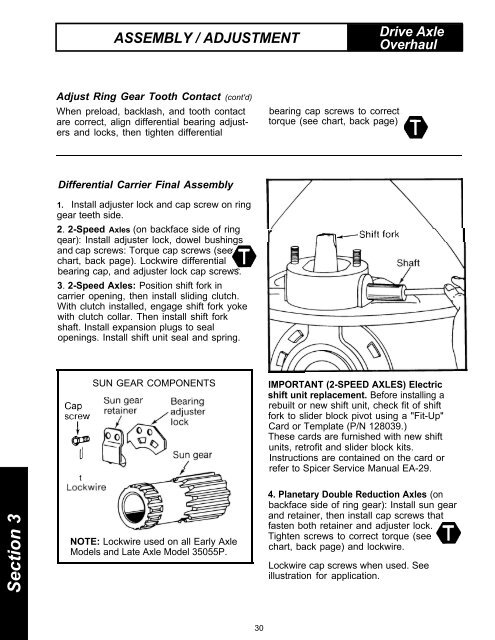
ASSEMBLY / ADJUSTMENTDrive <strong>Axle</strong>OverhaulAdjust Ring Gear Tooth Contact (cont'd)When preload, backlash, <strong>and</strong> tooth contactare correct, align differential bearing adjusters<strong>and</strong> locks, then tighten differentialbearing cap screws to correcttorque (see chart, back page)Differential Carrier Final Assembly1. Install adjuster lock <strong>and</strong> cap screw on ringgear teeth side.2. 2-<strong>Speed</strong> <strong>Axle</strong>s (on backface side of ringqear): Install adjuster lock, dowel bushings<strong>and</strong> cap screws: Torque cap screws (seechart, back page). Lockwire differentialbearing cap, <strong>and</strong> adjuster lock cap screws.3. 2-<strong>Speed</strong> <strong>Axle</strong>s: Position shift fork incarrier opening, then install sliding clutch.With clutch installed, engage shift fork yokewith clutch collar. Then install shift forkshaft. Install expansion plugs to sealopenings. Install shift unit seal <strong>and</strong> spring.rSection 3tSUN GEAR COMPONENTSNOTE: Lockwire used on all Early <strong>Axle</strong>Models <strong>and</strong> Late <strong>Axle</strong> Model 35055P.IMPORTANT (2-SPEED AXLES) Electricshift unit replacement. Before installing arebuilt or new shift unit, check fit of shiftfork to slider block pivot using a "Fit-Up"Card or Template (P/N 128039.)These cards are furnished with new shiftunits, retrofit <strong>and</strong> slider block kits.Instructions are contained on the card orrefer to Spicer <strong>Service</strong> <strong>Manual</strong> EA-29.4. Planetary <strong>Double</strong> Reduction <strong>Axle</strong>s (onbackface side of ring gear): Install sun gear<strong>and</strong> retainer, then install cap screws thatfasten both retainer <strong>and</strong> adjuster lock.Tighten screws to correct torque (seechart, back page) <strong>and</strong> lockwire.Lockwire cap screws when used. Seeillustration for application.30