analogue signal conditioning waveseries·microseries·mcz-series
analogue signal conditioning waveseries·microseries·mcz-series
analogue signal conditioning waveseries·microseries·mcz-series

Create successful ePaper yourself
Turn your PDF publications into a flip-book with our unique Google optimized e-Paper software.
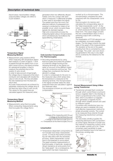
Description of technical data(input/output, input/auxiliary voltage,output/auxiliary voltage) one refers to3-port isolation.Temperature SignalMeasuring Method• Measurement using resistors (RTD)When measuring with temperature-dependentresistors a current of approx. 1.5mAis passed through the resistor from a constantcurrent source in the <strong>signal</strong> converter.An operational amplifier is used tomeasure the potential drop at theresistor (2-wire circuit).In order to take account of lead length,the voltage drop is measured at the returnconductor and calculated with double thevalue (3-wire circuit). This thus simulatesthe wire resistances from the feed andreturn lines.Accurate measurements are achieved byseparately measuring the voltage drop atthe feed and return lines (4-wire circuit).The values for the supply lines arecalculated against the measured value.Temperature SignalMeasuring Method• Measurements using thermocouplesWhen conducting measurements usingthermocouples the voltage that isgenerated when two differently alloyedmetals come into contact with eachother is measured. A differential amplifieris then used to recondition the <strong>signal</strong>.The easiest (and thus the most costeffective) method of subsequent processingis conducted by means of anamplifier circuit, which converts these<strong>signal</strong>s into standard <strong>signal</strong>s.High-end components process themeasuring <strong>signal</strong> using a microprocessor,which simultaneously reconditions the<strong>signal</strong> (filtering, linearisation).Cold Junction CompensationFor Thermocouples• Recording temperatures by usingthermocouples encounters the problemof a thermal voltage forming at theclamping terminals on the <strong>signal</strong> converteron account of the different materialsin the conductors and bus bar. Thisvoltage then counteracts the thermalelement‘s voltage.In order to compensate for the error tothe measured value which arises here,the temperature is measured at theclamping terminal. The microprocessorin the <strong>signal</strong> converter reads the valuemeasured there and calculates it againstthe measured value.This procedure is known as cold junctioncompensation.Voltage at the measuring point (Vmeas)+ Voltage at the terminal (Vterminal)= Voltage at the thermocouple (Vthermo)==> Temperature at the thermocouple (Tthermo)Linearisation• Temperature-dependent components donot normally have linear characteristiccurves. To ensure that further processingcan take place with the necessaryaccuracy, these characteristic curveshave to be linearised to some extent.The graph showing measurements ofthermocouples, in particular, reveals significantdeviations at some points fromthe "ideal graph”. As a consequence, the<strong>signal</strong> which has been measured isworked up by a microprocessor. Themicroprocessor compares the valuemeasured with the characteristic curvefor thethermocouple in its memory andcalculates the corresponding value onthe "ideal characteristic curve”. At theoutput, it supplies the latter to an amplifier,which produces the <strong>analogue</strong> value inlinear form. The output stage convertsthis into a standardised value or into aswitching output with a switchingthreshold.The linearisation of PT100-elements canbe undertaken via simple amplifierstages. The first stage corrects the peakvalue of the graph of the measurements.The deviation at the end of the graphresulting from this is corrected by a secondstage. The under- and over-shootinggenerated in this way is very slightand is covered by the tolerance for themodule.Current Measurement Using A MeasuringTransformer• Transformer principle Each conductorthrough which current flows is surroundedby a magnetic field H, the intensity ofwhich is proportional to the current. Thefield, which is bundled in a magneticcore, generates a magnetic flux B,through which suitable sensors are usedto measure current.Converters with transformer-type couplingsare used to establish the mostcost effective measurement method forsimple sinusoidal currents. The currentto be measured flows directly throughthe measuring transformer‘s primarywinding.The secondary winding supplies themeasuring electronics with a proportionalcurrent <strong>signal</strong>. Because of power lossthis method of measuring current is limitedto smaller currents up to 5A. Theseconverters react sensitively to peakloads and therefore have to be fused onthe primary winding side.5