hager TX216 KNX/EIB DALI-Gateway - UTU
hager TX216 KNX/EIB DALI-Gateway - UTU
hager TX216 KNX/EIB DALI-Gateway - UTU
- No tags were found...

You also want an ePaper? Increase the reach of your titles
YUMPU automatically turns print PDFs into web optimized ePapers that Google loves.
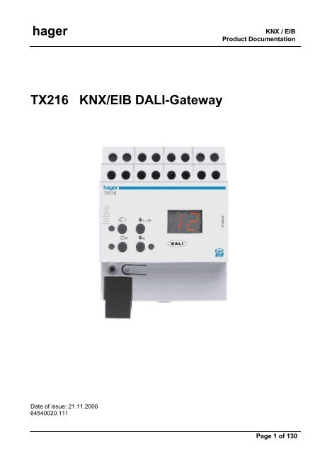
<strong>hager</strong>Product definition1 Product definition1.1 Product catalogueProduct name: <strong>DALI</strong> <strong>Gateway</strong>Use:<strong>Gateway</strong>Design: REG (rail-mounted device)Order no.: 6 4540 0201.2 FunctionThe <strong>DALI</strong> <strong>Gateway</strong> represents the interface between a <strong>KNX</strong>/<strong>EIB</strong> installation and a digital <strong>DALI</strong>(Digital Addressable Lighting Interface) lighting system. The <strong>DALI</strong> <strong>Gateway</strong> allows the switching anddimming of a maximum of 64 lamps including <strong>DALI</strong> device (e.g. electronic ballast). Each <strong>DALI</strong> lamp canbe assigned up to 32 different lighting groups that are controlled via the <strong>KNX</strong>/<strong>EIB</strong>. This permits theintegration of a room-specific light control of, for example, open-plan offices, multi-purpose rooms,assembly shops and training classrooms and lecture rooms into the higher-level <strong>KNX</strong>/<strong>EIB</strong> buildingmanagement. In addition, the lighting groups can be integrated into up to 16 scenes that makes itpossible to recall pre-programmed light moods or to save new light scenarios.The <strong>DALI</strong> <strong>Gateway</strong> permits the separate feedback of individual switching and brightness states of the<strong>DALI</strong> groups to the <strong>KNX</strong>/<strong>EIB</strong>. In addition, the general <strong>DALI</strong> operating status can be reported to the<strong>KNX</strong>/<strong>EIB</strong> (error status, short-circuit, status of supply voltage).The controls (4 pushbuttons) on the front panel of the device permit to manually dim or switch the <strong>DALI</strong>light groups on and off in parallel with the <strong>KNX</strong> / <strong>EIB</strong> even without bus voltage or in a unprogrammedstate (broadcast of all connected <strong>DALI</strong> lamps). This feature permits to quickly test the operability ofconnected consumers.The <strong>DALI</strong> <strong>Gateway</strong> is able to check the devices integrated into the <strong>DALI</strong> system for integrity. Thereplacement of a defect electronic ballast device by a new one, for example, can be detected if the“Automatic device replacement” has been activated. The decoding of the parameterized data into thenew electronic ballast device is carried out fully automatic by the <strong>Gateway</strong> without any specialcommissioning. That makes the corrective maintenance of a <strong>DALI</strong> system much easier.The configuration and commissioning of the <strong>DALI</strong> <strong>Gateway</strong> takes place via a plug-in that is integratedinto the ETS 3. For project design and commissioning of this device it is recommended to use theETS3.0d. The advantages with regard to downloading (shorter loading times) are available only if thisnew ETS patch version or later versions are used. Other tools besides hardware and software are notrequired for the commissioning of the device.Seite 3 von 130
<strong>hager</strong>Fitting, electrical connection and operationThe functionalities that can be preset with the ETS independently for each lighting group include, forinstance, separately parameterizable brightness ranges, extended feedback functions, disable functionor, alternatively, a forced-control position function, separately adjustable dimming response, time delayand Staircase timer function with pre-warning and soft dimming functions.Moreover, each lighting group can be integrated into up to 16 scenes with different brightness values.Centralized switching of all groups is also possible. In addition, the brightness values of the groups canbe set separately in case of bus voltage failure or bus voltage return and after programming with theETS.The Power for the <strong>DALI</strong> <strong>Gateway</strong> is entirely supplied by the separate mains connection. The mainsvoltage has to be switched on for controlling the <strong>DALI</strong> interface or programming with the ETS. Thedevice is designed for fitting on mounting rails in closed compact boxes or in power distributions infixed installations in dry rooms.2 Fitting, electrical connection and operation2.1 Safety instructionsElectrical equipment must be installed and fitted only by qualified electricians. Observe thecurrent accident prevention regulations.Failure to observe any of the installation instructions may cause damage to the device andresult in fire and other hazards.Before working on the device or before replacing the connected <strong>DALI</strong> devices, disconnect thesupply voltage (by cutting out the circuit breaker) to avoid the risk of an electric shock.The <strong>DALI</strong> <strong>Gateway</strong> is not suited for safe disconnection of the mains supply.<strong>DALI</strong> is a functional extra-low voltage (FELV) device. Safe separation between <strong>KNX</strong>/<strong>EIB</strong> and<strong>DALI</strong> and mains voltage in installations must be ensured. A minimum spacing of 4 mm must beensured between bus wires and <strong>DALI</strong>/mains conductors.Do not open the device and do not operate it outside the scope of the technical specifications.Seite 4 von 130
<strong>hager</strong>Fitting, electrical connection and operation2.2 Device components(4) (3)da+ da- L N(6)ON/ALL OFFOFF/D A L I(5)(2)(1)(1): <strong>KNX</strong>/<strong>EIB</strong> bus connection(2): Programming key and programming LED (red). The programming LED blinks slowly when thesafe-state mode is active.(3): Screw terminals (L,N) for connection of mains voltage supply(4): Screw terminals (da+, da-) for connection of <strong>DALI</strong> line(5): 2-digit 7-segment display (red) for the display of the selected <strong>DALI</strong> group ("01"..."32" / blinking =group disabled) in manual control mode or for the display of more information:" ": Indicates <strong>DALI</strong> commissioning phase after an ETS programming operation or after mainsvoltage return. The display duration depends on the number of connected <strong>DALI</strong> devices(only briefly after mains voltage return)." ": Display in an unprogrammed state during manual control." ": Display of a false connection to the <strong>DALI</strong> connection terminals (da+, da+). Mains voltageconnected. <strong>DALI</strong> <strong>Gateway</strong> does not operate. The <strong>Gateway</strong> is ready for operation only afterthe error has been eliminated and after a new initialization (mains voltage return)." ": Indicates the automatic device replacement (cf. Chapter "2.5 Operation")." ": Indicates an error occurring during the automatic device replacement(cf. Chapter "2.5 Operation").The 7-segment display is switched off during bus mode.(6): Keypad for manual operation with status LEDSeite 5 von 130
<strong>hager</strong>Fitting, electrical connection and operationConnecting the device in order to supply the device electronics and the <strong>DALI</strong> interface withpower• Connect the mains voltage and the <strong>DALI</strong> system as shown in fig. 1 (connection example).L1L2L3Ndadada+ da- L NLNLNdadadadaON/ALL OFFOFF/D A L I<strong>DALI</strong> device1<strong>DALI</strong> device2. . . (max. 64)redblack<strong>EIB</strong>Fig. 1: Electrical connection of mains voltage and the <strong>DALI</strong> interface• The <strong>DALI</strong> system voltage is a functional extra-low voltage (FELV). Thus, the <strong>DALI</strong> interface has to betreated like a live line in compliance with the applicable installation prescriptions. The <strong>DALI</strong> <strong>Gateway</strong>supplies the system voltage. The installation has to ensure that all mains voltages of the connected<strong>DALI</strong> devices as well as the mains voltage supply of the <strong>DALI</strong> <strong>Gateway</strong> will be switched off whenactivating a <strong>DALI</strong> section.• For a better overview in the installation it is recommended to pay attention to the polarity of the <strong>DALI</strong>line. Basically, the compliance with the <strong>DALI</strong> polarity depends on the <strong>DALI</strong> devices that are used.• <strong>DALI</strong> devices (max. of 64) can be connected to different phase conductors (L1, L2, L3).Seite 7 von 130
<strong>hager</strong>Fitting, electrical connection and operationRemoving other control facilities<strong>DALI</strong> devices from some manufacturers feature extended functions (operation with mains voltage at the<strong>DALI</strong> terminal). When using the <strong>DALI</strong> <strong>Gateway</strong> as a control unit in the <strong>DALI</strong> system, other existingcontrol posts – especially when refitting existing systems – have to be removed, if necessary, from theinstallation!• Remove all corresponding control facilities as shown in figure 2 or ensure that no other control postsexist.L1L2L3Ndadada+ da- L NLNdadaON/ALL OFFOFF/D A L Iredblack<strong>EIB</strong>Figure 2: Removing other control facilities in the <strong>DALI</strong> system• Other control posts may also be, for instance, <strong>DALI</strong> centers, <strong>DALI</strong> potentiometers or similar controlcomponents. These control posts have to be removed from the <strong>DALI</strong> system as well in order toavoid system conflicts.• Only one <strong>DALI</strong> <strong>Gateway</strong> may be operated in a closed <strong>DALI</strong> system.• If the <strong>DALI</strong> gateway detects mains voltage at the <strong>DALI</strong> terminal (terminals da+ and da-), it will shutoff and display " ".Seite 8 von 130
<strong>hager</strong>Fitting, electrical connection and operationInstalling / removing the protective capTo protect the bus lines against hazardous voltages, especially in the area of the connecting terminals,a protective cap can be installed.The cap is installed with the bus terminal in place and the connected bus line led out at the rear.• To install the cap: Slide the cap over the bus connecting terminal until it is heard to engage (cf. Fig.3.A).• To remove the cap: Remove the cap by pressing the sides slightly and by pulling it out to the front(cf. Fig. 3.B).ABFig. 3: Installing / removing the protective capSeite 9 von 130
<strong>hager</strong>Fitting, electrical connection and operation2.4 CommissioningAfter installation of the <strong>Gateway</strong> and connection of the bus line and the mains supply as well as the<strong>DALI</strong> lines, the device can be put into operation. The following procedure is generally recommended...DANGER!Electric shock in case of accidental contact with live parts. Electric shocks can be fatal.Before working on the device, cut out the mains supply and cover up live parts in thesurroundings.Commissioning the device• Switch on the mains supply of the <strong>Gateway</strong>.• Switch on the bus voltageChecking the voltages: the red programming LED must light up when the programming key is beingpressed.• Program and project the physical address with the ETS.• The <strong>DALI</strong> <strong>Gateway</strong> is configured via a plug-in which is integrated into the ETS database. Start theplug-in (open the parameter view) and configure the <strong>KNX</strong>/<strong>EIB</strong> groups (cf. Chapter 4 “Softwaredescription”). Do not yet commission the <strong>DALI</strong>!• Close the plug-in and download the application program with the ETS.• Restart the plug-in (open the parameter view) and commission the <strong>DALI</strong> (cf. Chapter 4 “Softwaredescription”).• Close the plug-in in order to save the <strong>DALI</strong> configuration in the ETS database. Then proceed withdownloading the application program again.The <strong>DALI</strong> <strong>Gateway</strong> is now ready for operation.• ETS programming will not be possible if the mains voltage is not connected to the <strong>DALI</strong> <strong>Gateway</strong>.• The ETS plug-in will display a message during the closing, if the application program of the <strong>DALI</strong><strong>Gateway</strong> has to be reprogrammed in the cases described.Seite 10 von 130
<strong>hager</strong>Fitting, electrical connection and operation2.5 OperationThe <strong>DALI</strong> <strong>Gateway</strong> permits all lighting groups to be operated manually. The keypad features 4 functionkeys and 3 status LEDs on the front panel of the device that can be used to set the following modes ofoperation...– Bus mode: operation via touch sensors or other bus devices– Temporary manual control: local manual control via keypad, automatic return to bus mode,– Permanent manual control: local manual control via keypad• The control modes can be enabled or disabled via parameter settings in the ETS.• In manual control mode the groups cannot be controlled via the bus.• Manual control is possible only while the actuator is supplied with power from the mains. The manualcontrol mode will be terminated in case of a bus voltage return or mains voltage failure. While inbroadcast mode (unprogrammed <strong>DALI</strong> <strong>Gateway</strong>), a bus voltage return cannot abort the manualcontrol.• In bus mode, the manual control can be disabled via a telegram. An activated disable function willterminate the manual control.• Further details concerning the manual control, especially with respect to the available parametersettings and the interaction with other functions of the <strong>Gateway</strong>, can be found in chapter 4. "Softwaredescription" of this documentation.Seite 11 von 130
<strong>hager</strong>Fitting, electrical connection and operationControls and indicators for manual control(1)(2)(3)(4)ALL OFFON/ OFF/(5) (6) (7)(8)Fig. 4: Controls and indicators for manual control(1) key:Activates / deactivates manual control(2) LED :LED ON indicates permanent manual control.(3) ON/ keyShort press: Group ON / Long press: increases brightness of group.(4) Status LED ON/ :Indicates a group that is switched on (brightness: 1...100%) when LED ON in manual controlmode ).(5) OFF/ key:Short press: Group OFF / Long press: reduces brightness of group.(6) Status LED OFF/ :Indicates a group that is switched off (brightness: 0%) when LED ON in manual control mode.(7) ALL OFF key:All groups off (only in permanent manual control mode).(8) 7-segment display::Indicates the selected <strong>DALI</strong> group for the manual control("01"..."32" /blinking = group disabled). In addition, the following information can be displayedduring a manual control..." ": Manual control in unprogrammed state (broadcast mode). In this case, the <strong>DALI</strong> <strong>Gateway</strong>collectively controls all <strong>DALI</strong> devices present in the system via a broadcast command as therehave been no group assignments yet (requires ETS commissioning)." ": Indicates the automatic device replacement. The display duration depends on the numberof connected <strong>DALI</strong> devices. The display will extinguish, if the device replacement could becompleted without error." ": Indicates an error that occurred during the automatic device replacement. The devicereplacement could not be carried out. The display will automatically extinguish after 3 seconds.Seite 12 von 130
<strong>hager</strong>Fitting, electrical connection and operationPrioritiesThe <strong>DALI</strong> <strong>Gateway</strong> distinguishes between different functions that can affect a <strong>DALI</strong> group. In order toprevent conflicting output states, each available function has been assigned a certain priority. Thefunction with the higher priority overrides the one with the lower priority.– 1 st Priority: Manual control mode (highest priority)– 2 nd Priority: Forced-control position or disable function– 3 rd Priority: Direct bus mode (“Switching” & “Dimming” & “Brightness value” objects, scenes, centrafunction)Switching on the temporary manual control for the broadcast functionThe manual control for the broadcast function can be utilized while the <strong>DALI</strong> <strong>Gateway</strong> is in theunprogrammed state. As in this case no group configurations have been stored due to a missing ETSprogramming, the <strong>DALI</strong> <strong>Gateway</strong> will collectively control the connected <strong>DALI</strong> devices in manual controlper broadcast command.The <strong>DALI</strong> <strong>Gateway</strong> has not yet been programmed via the ETS.• Press the key briefly (< 1 s)." " is shown on the 7-segment display.• After 5 s without key-press, the <strong>Gateway</strong> will deactivate the manual control for the broadcast.• The <strong>Gateway</strong> is delivered with the broadcast mode activated. After programming via the ETS, it isalso possible to reactivate the broadcast mode any time by unloading the application program via theETS.Switching on the temporary manual control for broadcastThe <strong>DALI</strong> <strong>Gateway</strong> has not yet been programmed via the ETS.Temporary manual control mode for the broadcast has been activated.• No key-press for 5 s- or -• Press key twice.- or -• Switch off mains voltage supply.Temporary manual control mode for broadcast has now been terminated. The 7-segment display willextinguish.• When shutting off the temporary manual control mode for broadcast, the state selected by manualcontrol will not change.Switching on permanent manual control mode for broadcastThe <strong>DALI</strong> <strong>Gateway</strong> has not yet been programmed via the ETS.Manual control mode or temporary manual control mode for broadcast has not been activated.• Press the key for at least 5 s.The status LED is illuminated. " " is shown on the 7-segment display. Permanent manualcontrol mode for broadcast has been activatedSeite 13 von 130
<strong>hager</strong>Fitting, electrical connection and operationSwitching on the permanent manual control mode for broadcastPermanent manual control mode for broadcast has been activated.• Press the key for at least 5 s- or -• Switch off mains voltage supply.Permanent manual control mode for broadcast has now been terminated. The status LED and the7-segment display will extinguish.• When shutting off the temporary manual control mode for broadcast, the state selected by manualcontrol will not change.Operating <strong>DALI</strong> devices in manual control mode for broadcastThe <strong>DALI</strong> <strong>Gateway</strong> has not yet been programmed via the ETS.Manual control mode (permanent or temporary) has been activated.• Operate the devices by pressing the ON/ key or OFF/ key.Brief press: Collective switch on/off.Long press: Collective increase/decrease of brightness.Long press & releasing: Stopping collective dimming.All connected <strong>DALI</strong> devices will immediately execute the corresponding commands.Switching off all <strong>DALI</strong> devices in manual control mode for broadcastPermanent manual control mode for broadcast has been activated:• Press the ALL OFF key.All connected <strong>DALI</strong> devices will be immediately switched off (brightness: 0 %). The devices are notlocked. Collective activation is again possible after shutoff.• The "ALL-OFF" function is not available in temporary manual control mode.Activating temporary manual control modeIf the <strong>DALI</strong> <strong>Gateway</strong> has been programmed at least once via the ETS, at least one <strong>DALI</strong> group will becreated and configured. In this case, the created groups can be individually controlled via manualcontrol. The broadcast mode will be deactivated.The <strong>DALI</strong> <strong>Gateway</strong> has been programmed at least once via the ETS.Manual control has been enabled in the ETS.• Press the key briefly (< 1 s).The group number “01” will be shown on the 7-segment display.• After 5 s without a key-press, the <strong>Gateway</strong> automatically returns to the bus mode.• The <strong>Gateway</strong> is delivered with the broadcast mode activated. After programming via the ETS, thebroadcast mode can be reactivated any time by unloading the application program via the ETS.Seite 14 von 130
<strong>hager</strong>Fitting, electrical connection and operationDeactivating the temporary manual control modeTemporary manual control mode has been activated.• No key-press for 5 s- or -• select all groups successively by a brief press of the key. Now press the key once more.- or -• Shut off power supply or reset bus (bus voltage return).The temporary manual control mode is now terminated. The 7-segment display will extinguish.• When shutting off the temporary manual control mode, the state selected by manual control will notchange. If, however, a forced-control position or a disable function has been activated via the busprior or during the manual control, the <strong>DALI</strong> <strong>Gateway</strong> will execute the disable or forced responses forthe affected groups.Activating the permanent manual control modeThe <strong>DALI</strong> <strong>Gateway</strong> has been programmed at least once via the ETS.Manual control has been enabled in the ETS. Bus mode or temporary manual control mode has beenactivated.• Press the key for at least 5 sThe status LED lights up. The group number “01” will be shown on the 7-segment display.Permanent manual control mode is now activated:Deactivating permanent manual control modePermanent manual control mode is activated.• Press the key for at least 5 s- or -• Shut off power supply or reset bus (bus voltage return).The permanent manual control mode for broadcast has now been terminated. The status LED andthe 7-segment display will extinguish.• Depending on how the <strong>Gateway</strong> has been parameterized in the ETS, the groups will be set to thestate last adjusted via manual control or to the state internally tracked (direct control, forced-controlposition / disable function) when shutting off the permanent manual control.Seite 15 von 130
<strong>hager</strong>Fitting, electrical connection and operationControlling a <strong>DALI</strong> group manuallyThe <strong>DALI</strong> <strong>Gateway</strong> has been programmed at least once via the ETS.Manual control mode (permanent or temporary) has been activated.• Select desired group: Press the key briefly (repeatedly, if necessary).The 7-segment display will display the group number of the activated <strong>DALI</strong> group. The "ON/ "(1...100 %) or "OFF/ " (0 %) status LED on the keypad indicates the brightness of the group.• Control the group by pressing the ON/ or OFF/ key.Brief press: Switching on/off.Long press: Increasing/decreasing brightness.Long press & releasing: Stop dimming.The activated <strong>DALI</strong> group will immediately execute the corresponding commands.Switching off all groupsPermanent manual control mode has been activated:• Press the ALL OFF key.All groups are shut off immediately (brightness: 0 %). The groups are not locked. Subsequently, theycan again be individually controlled.• The "ALL-OFF" function is not available in temporary manual control mode.Disabling bus mode of individual groups manuallyThe <strong>DALI</strong> <strong>Gateway</strong> has been programmed at least once via the ETS.Permanent manual control mode has been activated:The disabling of the bus mode must have been enabled in the ETS.• Select group: Press the key briefly (repeatedly, if necessary)The 7-segment display will display the group number of the activated <strong>DALI</strong> group. The "ON/ "(1...100 %) or "OFF/ " (0 %) status LED on the keypad indicates the brightness of the group.• Press the ON/ and OFF/ keys simultaneously for at least 5 s.The relevant <strong>DALI</strong> group is now disabled (no bus mode possible).The 7-segment display for the relevant group is blinking.• To unlock, proceed in the same way.• A group that has been disabled manually can only be operated in the permanent manual controlmode.Seite 16 von 130
<strong>hager</strong>Fitting, electrical connection and operation<strong>DALI</strong> device replacementAfter the start of the automatic device replacement, the <strong>DALI</strong> <strong>Gateway</strong> can check the <strong>DALI</strong> system forthe integrity of the <strong>DALI</strong> devices that have been previously put into operation. If, for instance, theinstaller has replaced a defect <strong>DALI</strong> electronic ballast device with a new one, the <strong>DALI</strong> <strong>Gateway</strong> is ableto program the new electronic ballast device with the project data of the failed electronic ballast device.Thus, it is possible to replace a failed <strong>DALI</strong> device by a simple operation on the device without havingto set parameters with the ETS.The <strong>DALI</strong> <strong>Gateway</strong> has been programmed at least once via the ETS.The automatic device replacement must be activated in the ETS.Bus and mains voltage (on all <strong>DALI</strong> devices) must be switched on.The <strong>DALI</strong> system must have already been put into operation via the ETS plug-in.Only one <strong>DALI</strong> device may have failed and may be replaced.The device must be in bus mode (no active manual control)• Press the and ALL OFF keys simultaneously for at least 10 s.The automatic device replacement will be activated. The time required for this operation depends onthe number of <strong>DALI</strong> devices available in the system. The 7-segment display indicates " " (Learn)during the device replacement. If the replacement has been successful, the display will extinguish.• All other functions of the <strong>DALI</strong> <strong>Gateway</strong> are paused during the device replacement. The <strong>Gateway</strong>tracks all bus states received during the device replacement and regularly analysizes the valuestracked last (switching, dimming, brightness value, scenes, central function, forced-control position,disable function) at the end of the automatic device replacement. The device replacement willinterrupt any active forced-control position or disable function which will be activated again at the endof the replacement, if, in the meantime, the functions have not been deactivated via the bus. Thebehaviour as at the beginning of these functions will not be executed again.• Make sure that only one <strong>DALI</strong> device is being replaced in the way described. In case severalelectronic ballast devices have failed (possibly not connected to mains voltage) and been replaced,the electronic ballast devices cannot be positively identified and automatically be configured. In thiscase, a new <strong>DALI</strong> commissioning via the ETS plug-in is required.• If an error has occurred during the device replacement, the 7-segment display will indicate " "(Error) for 3 s. The procedure has to be carried out again by following the requirements and detailsas mentioned above.This signalling will take place even if the automatic device replacement has been activated without aprior <strong>DALI</strong> device replacement.Seite 17 von 130
<strong>hager</strong>Technical data3 Technical dataType of protection: IP 20Safety class:IIIMark of approval:<strong>KNX</strong> / <strong>EIB</strong> / VDEAmbient temperature: -5 °C ... +45 °CStorage / transport temperature: -25 °C ... +70 °C(Storage above + 45 °C reduces the lifetime)Mounting position:optional (screw terminals preferably on top)Minimum distances:noneType of fastening:Snap-fastening on DIN rail in closed cabinets (e.g. smalldistributions, etc.) / <strong>KNX</strong> / <strong>EIB</strong> data rail not required.<strong>KNX</strong> / <strong>EIB</strong> supplyVoltage:Power consumption:Connection:External supplyVoltage:Power consumption:Connection:Total power loss:Response to bus voltage failure:Response to bus voltage failureResponse to bus voltage return:Response to mains voltage return:21…32 V DC SELVtypically 150 mWstandard <strong>KNX</strong>/<strong>EIB</strong> bus connection terminal110...240 V AC +10 % / -15 %, 50/60 Hzmax. 6 Wwith screw terminals:0,5…4 mm² solid and stranded wire without ferrule0,5…2,5 mm² stranded wire with ferruleMax. tightening torque: 0.8 Nmmax. 3 Wdepending on parameterization(cf. chapter 4. "Software description")As per parameterization, the device can report the supply voltagefailure to the bus. Afterwards, the device will completely shutdown.depending on parameterization(cf. chapter 4. "Software description")The device will briefly initialize (" " display) and is then readyfor operation. As per parameterization, the device can report thereturn of supply voltage to the bus.The brightness of a <strong>DALI</strong> group depends on the parameterization(cf. Chapter 4. “Software description”).Seite 18 von 130
<strong>hager</strong>Technical data<strong>DALI</strong>:Voltage:Current:typically 16 V DCwith over-voltage protectiontypically 128 mA, max. 200 mA temporarilydesigned for a maximum of 64 <strong>DALI</strong> devices at 2 mAwith short-circuit and overload protection1200 bit/sacc. to DIN EN 60929 appendix E4Transmission rateProtocol:Cable lengths between<strong>Gateway</strong> and device:∅ 1,5 mm²max. 300 m∅ 1,0 mm²max. 238 m∅ 0,75 mm²max. 174 m∅ 0,5 mm²max. 116 mResistivity:max. 4 Ω (single length) / max. 8 Ω (main and return cable)Cable type: Specified by functional extra-low voltage. (FELV) /Preferably 2 free wires of a NYM installation line.Seite 19 von 130
<strong>hager</strong>Software specifications4 Software description4.1 Software specificationsETS search paths: - Illumination / Dimmer / <strong>DALI</strong> <strong>Gateway</strong>BAU used: TPUART + µC<strong>KNX</strong>/<strong>EIB</strong> type class: 3b - device with cert. PhL + stackConfiguration: S-mode standardPEI type:"00" Hex / "0" DecPEI connector: no connectorApplications:No. Summarized description: Name Version Executable frommask version1 Multi-functional control of up to 32 <strong>DALI</strong>groups with adjustable dimming response,time functions, scenes, disable function orforced-control position, Soft-ON or Soft-OFF functions and extended feedback.Centralized switching of all outputs is alsoavailable. In addition, the brightness valuesof the <strong>DALI</strong> groups can be separatelyadjusted in case of bus voltage failure orreturn or after programming with the ETS.<strong>DALI</strong> <strong>Gateway</strong>C00C02 EN<strong>DALI</strong> <strong>Gateway</strong>C00C12 EN0.2 (english)for ETS 3.0Versions a…c1.2 (english)for ETS3.0 fromversion donwards705Seite 20 von 130
<strong>hager</strong>"<strong>DALI</strong> <strong>Gateway</strong> C00Cx2" softwareScope of functions4.2 "<strong>DALI</strong> <strong>Gateway</strong> C00Cx2" software4.2.1 Scope of functionsGeneral:• Control of a maximum of 64 <strong>DALI</strong> devices in a max. of 32 groups.• Manual control of the groups independent of the bus (site operation with broadcast control).• Feedback of <strong>DALI</strong> error status or short-circuit and supply voltage failure message.• Central switching function.• Incorporation of the groups into up to 16 light-scenes possible.Channel-oriented:• Each group features the full scope of functions without any restrictions. All channel-orientedfunctions can be parameterized separately for each group. This feature permits independent andmulti-functional control of the <strong>DALI</strong> devices. However, the Staircase timer function can only beparameterized for groups 1 ... 16.• Switching feedback and brightness value: active (after changes or cyclical transmission to the bus)or passive (object read-out function) feedback function.• Adjusting the limit values for brightness is possible.• Dimming response can be parameterized.• Soft-On or Soft-Off function.• Disable function or, alternatively, forced-control position function can be parameterized for eachgroup. With the disable function, blinking of lighting groups is possible.• Timer functions (ON-delay, OFF-delay, staircase lighting function, also with pre-warning function).• Response to bus voltage failure and bus voltage return as well as after ETS programming can beadjusted for each group.Plug-in:• Convenient <strong>DALI</strong> commissioning without additional software components.• Test function for all created <strong>DALI</strong> groups or <strong>DALI</strong> devices: central ON/OFF switching, individualhardware check (ON / OFF, brightness value preset, device status), individual group check(switching, dimming) and scene check.• Export and import of preset parameters in XML format.• Printing function for creating a configuration report (overview of group assignments or of the entiredevice configuration).Seite 21 von 130
<strong>hager</strong>"<strong>DALI</strong> <strong>Gateway</strong> C00Cx2" softwareSoftware information4.2.2 Software informationETS project design and commissioningFor creating a project and for the commissioning of this device it is recommended to use the ETS3.0dversion. Advantages with regards to downloading (significantly shorter loading times) can be expectedonly if this ETS patch version or later versions are used. The advantages result from the use of the newmask version 7.5 and the ETS3 support.The product database required for the ETS3.0d is offered in the *.VD4 format. The correspondingapplication program has the version number “1.1”. For older versions of the ETS3 a separate productdatabase is available in the *.VD2 format. The application program for these ETS versions is version"0.1".As far as the scope of functions described in this documentation is concerned, there is no differencebetween the two application programs.When older ETS versions are updated to the level of version ETS3.0d or to that of later versions, anadditional tool in the form of an ETS add-in is available. This tool is capable of converting older productdatabases of application version "0.1", for instance from existing ETS2 projects, into the newapplication format (version "1.1"). This feature permits making use of the advantages of the ETS3.0dapplication in an easy way and without creating any changes to the project design. The ETS3 add-incan be obtained separately from the manufacturer and is free of charge.Safe-state modeIf the device - for instance as a result of errors in the project design or during commissioning - does notwork properly, the execution of the loaded application program can be paused by activating the safestatemode. In the safe-state mode, the outputs cannot be controlled via the bus. A manual control forbroadcast is the only feature that can be activated. The <strong>Gateway</strong> remains passive in safe-state modesince the application program is not being executed (state-of-execution: terminated). Only the systemsoftware is still functional so that the ETS diagnosis functions and also the programming of the devicecontinue to be possible.Activating safe-state mode• Disconnect the mains voltage supply.• Press the programming key and keep it pressed.• Switch on the mains voltage supply. Release the programming key only after the programming LEDstarts blinking slowly.The safe-state mode is now activated. With another brief press on the programming key, theprogramming mode can be switched on and off as usual also in the safe-state mode. Theprogramming LED will nonetheless continue to blink independent of the programming mode as longas the safe-state mode remains active.• The safe-state mode can be terminated by switching off the mains voltage supply or by programmingwith the ETS.• For the activation of the safe-state mode, the bus voltage does not have to be switched on.Unloading the application programThe application program can be unloaded via the ETS. In this case, only manual control is possible forthe broadcast of connected <strong>DALI</strong> devices.Seite 22 von 130
<strong>hager</strong>"<strong>DALI</strong> <strong>Gateway</strong> C00Cx2" softwareObject table4.2.3 Object tableNumber of communication objects: 216Number of addresses (max): 254Number of assignments (max): 255Dynamic table management: noMaximum table length: 255Objects affecting several channels:Function: ScenesObject Function Name Type DP type Flag208 Extension unit Scenes 1- byte 18.001 C, W, -, (R) 1Description: 1-byte object for recalling scenes or for storing new scene values.Function:<strong>DALI</strong> fault and performance monitoringObject Function Name Type DP type Flag210 Feedback <strong>DALI</strong> error status 1-byte --- C, W, T, (R) 1 2Description:1-byte object for transmitting the error status of <strong>DALI</strong> devices that are connectedindividually to the system to the bus. The following bit assignment is used:Bit 0…5: number of the <strong>DALI</strong> device (0…63)Bit 6: lamp error (0 = no error, 1 = error)Bit 7: electronic ballast error (0 = no error, 1 = error)Independent of the feedback parameter setting, this object can always receivetelegrams (ValueWrite) as a transmission request. A received telegram will beimmediately answered via this object (ValueWrite) by transmitting the current internalobject status. Bits 0...5 in a request telegram must include the number of the <strong>DALI</strong>device. Bits 6 and 7 have to be set to “1”. Otherwise, the request telegram will beignored.1 Each communication object can be read-out. The readout requires the setting of the R flag.2 Depending on the parameterization the feedback objects are either actively transmitting (T flag) or can be passively read-out (R flag).Seite 23 von 130
<strong>hager</strong>"<strong>DALI</strong> <strong>Gateway</strong> C00Cx2" softwareObject tableFunction: <strong>DALI</strong> monitoringObject Function Name Type DP type Flag211 Message <strong>DALI</strong> voltage failure 1-bit 1.005 C, -, T, (R) 1Description:1-bit object for reporting a mains voltage failure at the <strong>DALI</strong> <strong>Gateway</strong>.(mains voltage available = 0, mains voltage failure = 1)Function:<strong>DALI</strong> monitoringObject Function Name Type DP type FlagDescription:212 Message <strong>DALI</strong> short-circuit 1-bit 1.005 C, -, T, R 11-bit object for reporting a short-circuit in the <strong>DALI</strong> line.(no short-circuit = 0, short-circuit = 1)Function:Central functionObject Function Name Type DP type FlagDescription:213 Switching Central function 1-bit 1.001 C, W, – (R) 11-bit object for the central switching of assigned <strong>DALI</strong> groups. The polarity can beparameterized.Function:Manual controlObject Function Name Type DP type FlagDescription:214 Disable Manual control 1-bit 1.003 C, W, – (R) 11-bit object for disabling the keys for manual control on the device. The polarity can beparameterized.Function:Manual controlObject Function Name Type DP type FlagDescription:215 Status Manual control 1-bit 1.002 C, -, T, (R) 11-bit object for the status transmission of manual control. The object is "0", whenmanual control is deactivated (bus mode). The object is "1", when manual control isactivated. The user can determine whether the temporary or the permanent manualcontrol will be displayed as status information.1 Each communication object can be read-out. The readout requires the setting of the R flag.Seite 24 von 130
<strong>hager</strong>"<strong>DALI</strong> <strong>Gateway</strong> C00Cx2" softwareObject tableChannel-oriented objects:Function:Output switchingObject Function Name Type DP type FlagSwitching Group 1 ... 32 1-bit 1.001 C, W, -, (R) 10, 7, 14, … , 105112, 118, …, 202Description:1-bit object for switching a <strong>DALI</strong> group on or off("1" = switching on; "0" = switching off).Function:Output relative dimmingObject Function Name Type DP type Flag1, 8, 15, … , 106113, 119, …, 203Dimming Group 1 ... 32 4-bit 3.007 C, W, – (R) 1Description:4-bit object for the relative dimming of a <strong>DALI</strong> group.Function:Output absolute dimmingObject Function Name Type DP type FlagBrightness value Group 1 ... 32 1-byte 5.001 C, W, – (R) 12, 9, 16, … , 107114, 120, …, 204Description: 1-byte object for setting an absolute dimming value (brightness value 0...255)by the bus.Function:Absolute dimming feedbackObject Function Name Type DP type Flag3, 10, 17, … , 108 Brightness value Group 1 ... 32 1-byte 5.001 C, -, T, (L) 1 2115, 121, …, 205feedbackDescription: 1-byte object for transmitting feedback of an adjusted dimming value(brightness value 0…255) to the bus.Function:Switching feedbackObject Function Name Type DP type FlagSwitching feedback Group 1 ... 32 1-bit 1.001 C, -, T,( R) 1 24, 11, 18, … , 109116, 122, …, 206Description:1-bit object for transmitting feedback to the bus signalling the switching state(“1” = switched on / “0” = switched off).1 Each communication object can be read-out. The readout requires the setting of the R flag.2 Depending on the parameterization the feedback objects are either actively transmitting (T flag) or can be passively read-out (R flag).Seite 25 von 130
<strong>hager</strong>"<strong>DALI</strong> <strong>Gateway</strong> C00Cx2" softwareObject tableFunction: Staircase timer function 3Object Function Name Type DP type Flag5, 12, 19, … , 110 Staircase timer Group 1 ... 16 1-bit 1.010 C, W, -, (R) 1function start/stopDescription: 1-bit object for activating or deactivating the switching time of the Staircase timerfunction of an output ("1" = on / "0" = off).Function: Disable functionObject Function Name Type DP type FlagDisable Group 1 ... 32 1-bit 1.003 C, W, – (R) 16, 13, 20, … , 111117, 123, …, 207Description:1-bit object for disabling a group (polarity is parameterizable).Function: Forced-control position functionObject Function Name Type DP type Flag6, 13, 20, … , 111 Forced-control Group 1 ... 32 2-bit 2.001 C, W, – (R) 1117, 123, …, 207positionDescription: 2-bit object for the forced-control position of a group. The polarity will be provided bythe telegram.3 The Staircase timer function can only be parameterized for the first 16 groups.1 Each communication object can be read-out. The readout requires the setting of the R flag.Seite 26 von 130
<strong>hager</strong>"<strong>DALI</strong> <strong>Gateway</strong> C00Cx2" softwareFunctional description4.2.4 Functional description4.2.4.1 Application basics<strong>DALI</strong>The <strong>DALI</strong> <strong>Gateway</strong> represents the interface between a <strong>KNX</strong>/<strong>EIB</strong> building installation and a digital <strong>DALI</strong>(Digital Addressable Lighting Interface) lighting system. Normally, all <strong>DALI</strong> systems are room-orientedand deal with the high demands on functional light management in, for example, offices, training andconference rooms. Often, these applications make it necessary to incorporate the room-oriented <strong>DALI</strong>system also into the <strong>KNX</strong>/<strong>EIB</strong> facility management across buildings. That makes it possible not only tocontrol the <strong>DALI</strong> lighting system via the sensor components of the <strong>KNX</strong>/<strong>EIB</strong> but also to incorporate theshutter, heating and air conditioning systems already existent in the buildings into the lightmanagement.A <strong>DALI</strong> system can address a maximum of 64 devices. The <strong>Gateway</strong> itself does not count as a device.The <strong>DALI</strong> <strong>Gateway</strong> offers 32 <strong>KNX</strong>/<strong>EIB</strong> controllable groups that are parameterized in the ETS 3 similarto a dimming actuator channel. There are several communication objects available at the bus thatpermit, among other things, the switching, the dimming, the setting of brightness values or the time orscene control of a group. During the <strong>DALI</strong> commissioning, the <strong>DALI</strong> devices (max. of 64) will beoptionally assigned one or several groups of the <strong>Gateway</strong> (cf. figure 5 on the following page). It is thegroup assignment that makes it possible to control the <strong>DALI</strong> devices individually (individual assignment– only one device in the group) or collectively (multiple assignment – several devices in a group) via the<strong>KNX</strong>/<strong>EIB</strong>.A multiple assignment of <strong>DALI</strong> devices is possible for the groups 1...16 of the <strong>DALI</strong> <strong>Gateway</strong>. In thiscase the addressing takes place at the <strong>DALI</strong> via group addresses that the <strong>DALI</strong> <strong>Gateway</strong> configures“hidden” to the user. The <strong>DALI</strong> <strong>Gateway</strong> handles them independently. During the <strong>DALI</strong> commissioning,all affected devices will be automatically programmed.The groups 17...32 accept only individual assignments. Each group can be assigned only one <strong>DALI</strong>device. In this case, the <strong>DALI</strong> addressing takes place via an internally specified individual address.Only one device can be uniquely addressed via this individual address. This individual address will alsobe automatically assigned by the <strong>DALI</strong> <strong>Gateway</strong> during the <strong>DALI</strong> commissioning.The <strong>DALI</strong> commissioning takes place entirely via the plug-in embedded in the ETS 3 via the <strong>KNX</strong>/<strong>EIB</strong>bus line. No additional tool and no special programming link is required.The commissioning of the <strong>DALI</strong> devices as well as the <strong>DALI</strong> configuration or the <strong>DALI</strong> addressing takesplace fully automatic via the plug-in and the <strong>DALI</strong> <strong>Gateway</strong>. Only the assignment between the <strong>DALI</strong>device and the group must be carried out ‘manually’ in the commissioning environment of the plug-in.Different test or detection functions (separate switching on, switching off or blink function) available inthe plug-in make it also considerably easier to commission the different <strong>DALI</strong> devices.Seite 27 von 130
<strong>hager</strong>"<strong>DALI</strong> <strong>Gateway</strong> C00Cx2" softwareFunctional descriptionGroup 2Lamp 5Lamp 7Lamp 9Lamp 11Lamp 4Lamp 6Lamp 8Lamp 10Lamp 3Lamp 1Group 1Lamp 2Group 3Figure 5: Example of a grouping in the <strong>DALI</strong> systemIn the example of a grouping (cf. Figure 5) each one of the drawn-in lamps features a <strong>DALI</strong> devicewhich is assigned one or several groups. In the example, lamp 1 is part of an individual group. Thislamp can be controlled separately from the other lamps. The other lamps belong to group 2. Hence,they are collectively controlled. In addition, the lamps 2, 3, 6 and 7 can be controlled via group 3. Thus,groups 2 and 3 assigned to these lamps overlap.• <strong>DALI</strong> devices that are assigned several groups will always adjust to the state that has been adjustedlast via one of the assigned groups. In this case, the feedback of the switching status or thebrightness value of a group is not always unique.Example 1(cf. Figure 5): Group 2 is set to 10% brightness. Group 3 is then dimmed to a brightnessvalue of 20%. The lamps of group 3 will accept the brightness value of 20% which was invoked last.The feedback of group 2 remains on 10% although some of the devices belonging to the group havebeen set to 20% brightness.Example 2: group 2 is switched on and assumes the brightness value of 100%. Internally, the stateof group 3 remains set at 0% brightness (OFF). The brightness of group 3 is now increased. Thelamps of group 3 will adapt to the dimming (increasing brightness starting at minimum brightness)even though these lamps have already been switched on via group 2.Basically, the assignment of <strong>DALI</strong> devices to groups is arbitrary. For the reasons mentioned above itis recommended not to assign the devices to several groups at the <strong>DALI</strong>. Preferably, the devicesshould be allocated to separate instead of overlapping groups. A <strong>KNX</strong>/<strong>EIB</strong> link via the groupaddressing in the ETS is also preferred.Seite 28 von 130
<strong>hager</strong>"<strong>DALI</strong> <strong>Gateway</strong> C00Cx2" softwareFunctional descriptionThe <strong>DALI</strong> <strong>Gateway</strong> acts as the central control component (master-controller) in the system that alsoensures the power supply of the <strong>DALI</strong> interface. The <strong>DALI</strong> devices, e.g. <strong>DALI</strong> electronic ballast,function as slaves that transmit back the states or status reports to the master only upon request. It isthe function of the <strong>DALI</strong> <strong>Gateway</strong> only to transmit control commands received by the <strong>KNX</strong>/<strong>EIB</strong> to the<strong>DALI</strong> line as well as to control the devices. Further <strong>DALI</strong> control components in multi-master mode, e.g.an additional <strong>DALI</strong> center, a <strong>DALI</strong> potentiometer or power switching pushbuttons, are unnecessary andcan lead in some individual cases to malfunction in the <strong>DALI</strong> system. Therefore, it is necessary toremove other control components from the system – especially when refitting existing <strong>DALI</strong> systems.The <strong>DALI</strong> system is then entirely controlled by components of the <strong>KNX</strong>/<strong>EIB</strong> (cf. figure 6).Figure 6: Schematic diagram of a <strong>KNX</strong>/<strong>EIB</strong>-<strong>DALI</strong> system interconnection(example: <strong>DALI</strong> electronic ballast in different groups)Seite 29 von 130
<strong>hager</strong>"<strong>DALI</strong> <strong>Gateway</strong> C00Cx2" softwareFunctional descriptionThe communication via the <strong>DALI</strong> <strong>Gateway</strong> between the <strong>KNX</strong>/<strong>EIB</strong> and the <strong>DALI</strong> interface is bidirectional.On the one hand, the <strong>Gateway</strong> receives telegrams from the <strong>KNX</strong>/<strong>EIB</strong> that either directlyinfluence the brightness status of a <strong>DALI</strong> group (e.g. by switching, dimming, setting the brightnessvalue or scene recall) or indirectly adjust it (e.g. via time, disable or forced-control position functions).Thus, the <strong>DALI</strong> <strong>Gateway</strong> internally always detects the current brightness states of the groups andforwards brightness commands to the <strong>DALI</strong> devices which will then adjust to the correspondingbrightness.On the other hand, the internally tracked switching or brightness states of the groups can be reportedback to the <strong>KNX</strong>/<strong>EIB</strong>. The transmission of status information of the <strong>DALI</strong> devices (lamp error, electronicballast error) or the <strong>Gateway</strong> (mains voltage failure, <strong>DALI</strong> short-circuit) to the bus is possible.In addition, all groups controllable by up to 32 <strong>KNX</strong>/<strong>EIB</strong>s can be integrated in 16 independent scenes.In a scene, brightness values can be separately parameterized for each <strong>DALI</strong> group in the ETS. Theycan also be adjusted any time later during the on-going operation.• If the <strong>DALI</strong> devices have been assigned several groups (overlapping groups) and if these groupshave been assigned a common scene, the devices will adjust to the brightness value of the groupwith the highest number.Example: An electronic ballast device has been assigned groups 1 and 2. Both groups have beenassigned scene 1. When recalling a scene, group 1 is to adjust to a brightness of 10 % and group 2to 20 %. If scene 1 is recalled the electronic ballast device is adjusted to 20 % brightness sincegroup 2 has the higher group number.Seite 30 von 130
<strong>hager</strong>"<strong>DALI</strong> <strong>Gateway</strong> C00Cx2" softwareFunctional descriptionETS plug-inThe setting of all device parameters as well as the <strong>DALI</strong> commissioning takes place entirely via theplug-in embedded in the ETS 3. The plug-in is part of the product database and will be automaticallyinstalled when the product file is imported into the ETS database. That makes the installation of anadditional software unnecessary.The plug-in is started by including the <strong>DALI</strong> <strong>Gateway</strong> in an ETS 3 project and by opening the parameterview of this device. Afterwards, the ETS programmer will have the view shown in figure 7.Figure 7: Project interface of the ETS 3 plug-inThe project-interface is derived from the general ETS 3 parameter view and is divided into the samefields. The tree structure in the left subwindow displays all parameter pages of the parameters affectingseveral channels and devices as well as the group related parameters. The window also displays thepages with the options for the commissioning and the import/export function.The individual pages can be selected and opened with mouse-clicks or via keyboard navigation. Theparameters assigned to the parameter page or the options for the commissioning will become visible inthe right subwindow.There are 4 buttons located in the lower window section. The “OK” button will close the plug-in andsave the selected parameters and configurations in the ETS database.The “Cancel” button will close the plug-in without saving the data into the ETS database. Any changesmade to the parameter settings will be lost. Previously set <strong>DALI</strong> commissioning parameters will also notbe accepted into the ETS database. However, a <strong>DALI</strong> commissioning that has been executed beforewill remain in the <strong>DALI</strong> devices.The “Default” button will restore the default values. All changes made to the parameter settings thatdiffer from the default settings will be discarded. All created groups will be deleted. The <strong>DALI</strong>commissioning parameters are also affected. The assignment of <strong>DALI</strong> devices to groups will get lost.However, a <strong>DALI</strong> commissioning executed before will remain in the <strong>DALI</strong> devices if the “Default” buttonis not activated in the commissioning environment. For this reason, a new <strong>DALI</strong> commissioning shouldalways be carried out.By activating the “Help” button this <strong>DALI</strong> <strong>Gateway</strong> product documentation will open as an online helppage.Seite 31 von 130
<strong>hager</strong>"<strong>DALI</strong> <strong>Gateway</strong> C00Cx2" softwareFunctional descriptionHandling <strong>DALI</strong> groups:The <strong>DALI</strong> <strong>Gateway</strong> can distinguish up to 32 different groups which are created and configuredseparately. Group 1 has already been created in the start view of the plug-in. Additional groups can beadded by selecting “Groups” in the tree structure view followed by the “New” command via the contextmenu (right mouse click) (cf. Figure 8).Figure 8: Adding <strong>DALI</strong> groupsAny created group can also be copied via the “Copy” command in the context menu of a group nodeand inserted as a new group in the “Groups” node. The parameter settings of the copied group will beadopted.It is also possible to insert a previously copied group into an already existing one. All parametersettings of the existing group will be adopted by the copied group.Each created group receives a unique group number that is shown in square brackets in front of thegroup name. The group number will be shown in the 7-segment display on the front panel whenmanual control has been activated.Created groups can be deleted at any time by selecting a group followed by the “Delete” command inthe context menu. It should be noted that at least one group must have been created.Each group can be assigned a name by selecting a group followed by the “Rename” command via thecontext menu. It is recommended to assign a unique name to each group (e.g. “Light-band windowSouth”, “Spots office center”, etc.). The name may not exceed 28 characters and may includealphanumerical as well as special characters.• Each group can be parameterized independently in the plug-in. During the <strong>DALI</strong> commissioning, theindividual <strong>DALI</strong> devices will be programmed with the parameterization data once the groupparameterization has been completed. All devices assigned to a <strong>DALI</strong> group will be identically putinto operation.If, however, <strong>DALI</strong> devices have been assigned to several groups, these devices will receive theproject design with the highest group number.Seite 32 von 130
<strong>hager</strong>"<strong>DALI</strong> <strong>Gateway</strong> C00Cx2" softwareFunctional descriptionImport, export, printing:The project design of the device (all parameter settings and <strong>KNX</strong>/<strong>EIB</strong> group addresses) as well as all<strong>DALI</strong> commissioning parameters (all detected <strong>DALI</strong> devices and group assignments) can be backed upby exporting an external XML file. Backed up data can be imported at any time. That way it is easy toback up data ‘outside’ the ETS database as well. In addition, an existing project design can also beimported into other <strong>DALI</strong> <strong>Gateway</strong>s as a master which makes it considerably easier to configure a newdevice.The import and export function can be executed on the “Import / Export / Printing” parameter page ofthe plug-in.By activating the “Export” button, the current device configuration of the plug-in will be exported into anXML file. The memory location for the file can be specified prior to the export. The plug-in displays theprogress during the export. This may take some time. The time required depends on the number ofexisting <strong>DALI</strong> devices and the number of the created groups and enabled functions.• The data is exported in an "*.XML" format. In order to export an XML file, the Microsoft XML parser4.0 must be installed on the PC ("msxml4.dll"). The program can be downloaded on the Microsofthomepage (www.microsoft.com/downloads) for operating systems from Windows 98 onwards(search term “msxml”). The required program package is "MSXML 4.0 Service Pack 2 (MicrosoftXML Core Services)" or a later version.In case the program package is not installed, the plug-in of the <strong>DALI</strong> <strong>Gateway</strong> will report an errorwhen executing an export command. More recent operating systems come with the programpackage already preinstalled.Activating the “Import” button will import a previously exported XML file into the device configuration. Itshould be noted that the current configuration of the plug-in including the commissioning parameters ofthe <strong>DALI</strong> devices will be overwritten in the ETS by the import. The plug-in will display a warningmessage before proceeding with the import (cf. Figure 9).Figure 9: Warning message prior to the importSeite 33 von 130
<strong>hager</strong>"<strong>DALI</strong> <strong>Gateway</strong> C00Cx2" softwareFunctional descriptionAfter the import has been confirmed the plug-in will ask whether the import is to take place with orwithout <strong>KNX</strong>/<strong>EIB</strong> group addresses (cf. figure 10).When importing without group addresses the plug-in will not transfer any associations betweencommunication objects and group addresses of the XML file. Objects are not associated with any groupaddresses after the import.It is also possible to import a XML file with the <strong>KNX</strong>/<strong>EIB</strong> group addresses stored in the file. Beforetransferring, the plug-in will check all group addresses stored in the XML file. The plug-in will discardthe group addresses if they have either not been created in the current ETS project or if (in case theyare available) are of the wrong data type.Figure 10: Import dialogue with or without <strong>KNX</strong>/<strong>EIB</strong> group addresses• The import will also overwrite all <strong>DALI</strong> commissioning parameters (detected <strong>DALI</strong> devices and groupassignments) with the data of the XML file. It must be pointed out that only the data stored in the ETSdatabase will be adjusted. A prior <strong>DALI</strong> commissioning including the programming of the <strong>DALI</strong>devices will remain in the <strong>DALI</strong> devices. For this reason, a new <strong>DALI</strong> commissioning should alwaysbe carried out after the import of an XML file.Seite 34 von 130
<strong>hager</strong>"<strong>DALI</strong> <strong>Gateway</strong> C00Cx2" softwareFunctional descriptionThe plug-in of the <strong>DALI</strong> <strong>Gateway</strong> also permits the printing of the entire device configuration includingthe project design of the groups, the scene configuration and all <strong>DALI</strong> commissioning parameters inform of a configuration report.The print function can be found on the “Import / Export / Printing” parameter page of the plug-in.After activating the “Print” button, the plug-in will ask whether you want to print the complete deviceconfiguration or only part of the <strong>DALI</strong> commissioning parameters including the <strong>DALI</strong> group assignments(cf. figure 11).Figure 11: Print dialogue for selecting printing optionsThe project design of the <strong>DALI</strong> groups, the <strong>DALI</strong> commissioning and the <strong>DALI</strong> test are described in thefollowing chapters.Seite 35 von 130
<strong>hager</strong>"<strong>DALI</strong> <strong>Gateway</strong> C00Cx2" softwareFunctional description4.2.4.2 Functions affecting several devicesFeedback for <strong>DALI</strong> error statusThe <strong>DALI</strong> <strong>Gateway</strong> permits the error status feedback of the connected <strong>DALI</strong> devices. In case of failure,the <strong>DALI</strong> components will send “lamp error” or “Error in device (e.g. electronic ballast error)” statusinformation to the <strong>DALI</strong> <strong>Gateway</strong> where it will be stored. The <strong>DALI</strong> <strong>Gateway</strong> provides all statusinformation via the “<strong>DALI</strong> error status” 1-byte collective feedback object 210 on the <strong>KNX</strong>/<strong>EIB</strong> side.The data format of the collective feedback object is described in table 1.Bits7 (MSB) 6 5 4 3 2 1 0 (LSB)Number of <strong>DALI</strong> device (0...63)Lamp error (0 = no error, 1 = error)Device error, e.g. internal electronic ballast error (0 = no error, 1 = error)Table 1: Data format of the collective feedback object for <strong>DALI</strong> error status.A feedback telegram will always transmit the status information of only one <strong>DALI</strong> device.The bits 0...3 of the 1-byte feedback telegram identify the faulty device via the device number. Thenumbers of all <strong>DALI</strong> devices are shown in square brackets in front of the device name in thecommissioning environment of the ETS plug-in or in the configuration report (print function) (e.g. [1] forthe first <strong>DALI</strong> device). By assigning a meaningful device name during the commissioning in addition tothe number (e.g. “[1] electronic ballast row 1 right”), it will be easy to identify which device at whatlocation actually is reporting the error. The device numbers will be automatically assigned during thecommissioning when searching for existing devices.• It has to be noted that the device number found in the plug-in or printed in the documentation iscounted in decimals from 1 to 64. The numbers given in the feedback telegram are equivalent from 0to 63.Bit 6 will be set in the feedback telegram if the applicable <strong>DALI</strong> device has detected a lamp error (e.g.defect lamps, cable break to the lamp socket). In case of no lamp defect this bit is deleted (“0”).Bit 7 of the feedback will be set if the identified device has reported a general error (e.g. internalelectronic ballast error) or if the applicable device can no longer be addressed via the <strong>DALI</strong> <strong>Gateway</strong>(e.g. the device is disconnected from the <strong>DALI</strong> line). In case of no device error this bit is deleted (“0”).As the master in the <strong>DALI</strong> system, the <strong>DALI</strong> <strong>Gateway</strong> will request periodically every second the statusof the connected devices (slaves) as soon as it is ready for operation. That means that in a system witha maximum of 64 <strong>DALI</strong> devices, an error will be identified no later than after 64 seconds. An erroroccurring in the device has to be eliminated (switch off mains voltage and follow the manufacturer’sguidelines!). The <strong>DALI</strong> <strong>Gateway</strong> will automatically detect an eliminated error after the commissioning ofthe repaired device and will remove the error status in the feedback.Seite 36 von 130
<strong>hager</strong>"<strong>DALI</strong> <strong>Gateway</strong> C00Cx2" softwareFunctional descriptionSetting the feedback for the <strong>DALI</strong> error statusThe ETS parameterization allows to define whether the error status feedback is to be transmittedactively to the <strong>KNX</strong>/<strong>EIB</strong> (telegram transmission when status has changed) or passively (telegramtransmission only in case of a trigger request).• Set the “<strong>DALI</strong> error status feedback ?” parameter on the “General” parameter page to “Yes, feedbackobject is an active message object”.As soon as a change of the status of a connected <strong>DALI</strong> device has been detected during theperiodical status request, a corresponding feedback telegram will be transmitted actively to the<strong>KNX</strong>/<strong>EIB</strong>. The feedback telegram relating to a <strong>DALI</strong> device will be transmitted only once after thedetection and the elimination of the error.• An internally stored error will get lost in case of a mains voltage failure. Thus, no more feedback willbe transmitted once an error has been eliminated by switching off and on again the mains voltage (atthe <strong>DALI</strong> <strong>Gateway</strong> as well).• The <strong>DALI</strong> <strong>Gateway</strong> initializes after the programming of the ETS or after the mains voltage has beenswitched on. If a <strong>DALI</strong> error has been detected the <strong>Gateway</strong> will proceed to transmit thecorresponding feedback telegram. The “<strong>DALI</strong> error status” will not be automatically transmitted to thebus after the return of bus voltage (mains voltage at the <strong>Gateway</strong> is permanently switched on duringbus failure).• Set the “<strong>DALI</strong> error status feedback ?” parameter on the “General” parameter page to “Yes, feedbackobject is a passive status object”.In case of a detected error there will be no automatic telegram transmission to the <strong>KNX</strong>/<strong>EIB</strong>. In orderto determine the error status of a <strong>DALI</strong> device, the “<strong>DALI</strong> error status” communication object 210 hasto be externally written by a 1-byte trigger telegram (ValueWrite). The bits 0...5 of the triggertelegram have to include the number of the <strong>DALI</strong> device whose status has been requested (cf. Table1). The bits 6 and 7 have to be set to “1”. Otherwise the trigger telegram will be ignored.The <strong>DALI</strong> <strong>Gateway</strong> will immediately respond to a received and valid trigger telegram by transmittingthe current status once.• The <strong>Gateway</strong> will respond with deleted error bits to trigger requests for device numbers that are notavailable in the <strong>DALI</strong> system.• The <strong>DALI</strong> <strong>Gateway</strong> will respond to a Read telegram (ValueRead) that has been transmitted to the“<strong>DALI</strong> error status” communication object 210 by sending the object value that was updated last(ValueResponse). Thus, <strong>DALI</strong> devices cannot be uniquely addressed.• Set the "<strong>DALI</strong> error status feedback ?" parameter on the "General" parameter page to "No".This will deactivate the <strong>DALI</strong> error status. The communication object is now hidden.Seite 37 von 130
<strong>hager</strong>"<strong>DALI</strong> <strong>Gateway</strong> C00Cx2" softwareFunctional descriptionFeedback for the mains voltage supply on the <strong>DALI</strong> <strong>Gateway</strong>The <strong>DALI</strong> <strong>Gateway</strong> is able to monitor its supply voltage at the connection. In case of failure the<strong>Gateway</strong> is able to send a message telegram to the <strong>KNX</strong>/<strong>EIB</strong> before shutting down. Optionally, it ispossible to have the mains voltage supply confirmed.If the mains voltage supply of the <strong>Gateway</strong> and the connected <strong>DALI</strong> devices are connected to the samephase connector, it is possible to monitor the operating status of the entire <strong>DALI</strong> system by analyzingthe feedback of the mains voltage.The <strong>DALI</strong> <strong>Gateway</strong> uses the independent “<strong>DALI</strong> voltage failure” 1-bit communication object 211 forgiving feedback to a voltage drop or return of voltage. The polarity of the telegram is preset: (mainsvoltage available = 0, mains voltage failure = 1).Setting the feedback for the mains voltage supplyThe ETS parameterization allows to define whether only a mains voltage supply failure of the <strong>DALI</strong><strong>Gateway</strong> or whether a mains voltage return is also to be reported to the <strong>KNX</strong>/<strong>EIB</strong>. The telegram isalways actively transmitted. As soon as the status of the mains voltage has changed, a one-timefeedback telegram will be transmitted.• Set the "<strong>DALI</strong> <strong>Gateway</strong> mains voltage failure / return feedback ?" parameter on the "General"parameter page to "Yes (only in case of a voltage failure)”.As soon as a mains voltage failure has been detected at the <strong>DALI</strong> <strong>Gateway</strong>, the <strong>Gateway</strong> willimmediately transmit a feedback telegram. Then it will shut down.• Set the "<strong>DALI</strong> <strong>Gateway</strong> mains voltage failure / return feedback ?" parameter on the "General"parameter page to "Yes (only in case of voltage failure and return)”.As soon as a mains voltage failure has been detected at the <strong>DALI</strong> <strong>Gateway</strong>, the <strong>Gateway</strong> willimmediately transmit a feedback telegram. Then it will shut down. The <strong>DALI</strong> <strong>Gateway</strong> initializes whenswitching on the mains voltage supply. It will then transmit a feedback telegram and indicate that themains voltage is on.• Set the "<strong>DALI</strong> <strong>Gateway</strong> mains voltage failure / return feedback ?" parameter on the "General"parameter page to "No".The feedback mains voltage supply status will be deactivated. The communication object is nowhidden.• Feedback on a mains voltage failure can only be transmitted if the bus voltage has been connectedand switched on at the time of the failure.In case no bus voltage has been connected or switched on at the time of the voltage return, there willbe also no feedback on the mains voltage return. The feedback will not be stored. Thus, no feedbackwill be transmitted even at a later time when switching on the bus voltage.• The “<strong>DALI</strong> voltage failure” feedback is not automatically transmitted to the bus after the return of busvoltage or after ETS programming with bus voltage applied at the <strong>DALI</strong> <strong>Gateway</strong>.Seite 38 von 130
<strong>hager</strong>"<strong>DALI</strong> <strong>Gateway</strong> C00Cx2" softwareFunctional descriptionFeedback for <strong>DALI</strong> short-circuitThe <strong>DALI</strong> <strong>Gateway</strong> detects short-circuits in the <strong>DALI</strong> line – for instance in case of an installation error.As soon as a short-circuit has been identified in the <strong>DALI</strong> line (with mains voltage applied), the <strong>DALI</strong><strong>Gateway</strong> will send a feedback to the <strong>KNX</strong>/<strong>EIB</strong> if the feedback function has been enabled for a <strong>DALI</strong>short-circuit.The <strong>DALI</strong> <strong>Gateway</strong> utilizes the independent “<strong>DALI</strong> short-circuit” 1-bit communication object 212 for a<strong>DALI</strong> short-circuit feedback. The polarity of the telegram is preset: (no short-circuit = 0, short-circuit = 1)Setting the feedback for <strong>DALI</strong> short-circuitThe ETS allows to set parameters that determine whether a <strong>DALI</strong> feedback on a short-circuit is to betransmitted to the <strong>KNX</strong>/<strong>EIB</strong>. If enabled, the telegram is always actively transmitted. If a short-circuit hasbeen detected or eliminated, the <strong>Gateway</strong> will transmit a feedback telegram in each case.• Set the "<strong>DALI</strong> short-circuit feedback ?” parameter on the "General" parameter page to "Yes".The <strong>DALI</strong> short-circuit feedback is activated and the communication object is enabled.• Set the "<strong>DALI</strong> short-circuit feedback ?” parameter on the "General" parameter page to "No".The <strong>DALI</strong> short-circuit feedback function is deactivated. The communication object is hidden.• The connected <strong>DALI</strong> devices will also respond to a short-circuit in the <strong>DALI</strong> line. The devices willadjust to the preset "SystemFailureLevel". This value will be programmed into the <strong>DALI</strong> devicesduring the commissioning of the <strong>DALI</strong> <strong>Gateway</strong> and corresponds to the “Response to bus voltagefailure” value that can be parameterized in the ETS for each group.• Because the brightness of the connected <strong>DALI</strong> devices might possibly change in case of a shortcircuit("SystemFailureLevel"), the <strong>DALI</strong> <strong>Gateway</strong> will also transmit feedback on the switching stateand brightness value to the bus if these feedback functions have been enabled.• Feedback on a <strong>DALI</strong> short-circuit can only be transmitted if the bus voltage has been connected andswitched on at the time of the short-circuit.In case no bus voltage has been connected or switched on at the time of the short-circuit, there willalso be no feedback transmission. The feedback, however, will be stored so it can be transmitted ata later time after the bus voltage has been applied.• The <strong>DALI</strong> <strong>Gateway</strong> initializes after the ETS programming or after the mains voltage has beenapplied. If a short-circuit has been detected in the <strong>DALI</strong> line, the <strong>Gateway</strong> will proceed to transmit thecorresponding feedback telegram. The “<strong>DALI</strong> short-circuit” will not be automatically transmitted to thebus after the return of bus voltage (mains voltage at the <strong>Gateway</strong> is permanently switched on duringbus failure).Seite 39 von 130
<strong>hager</strong>"<strong>DALI</strong> <strong>Gateway</strong> C00Cx2" softwareFunctional description<strong>DALI</strong> device replacementAfter the start of the automatic device replacement, the <strong>DALI</strong> <strong>Gateway</strong> can check the <strong>DALI</strong> system forthe integrity of the <strong>DALI</strong> devices previously put into operation. If, for instance, the installer has replaceda defect <strong>DALI</strong> electronic ballast device with a new one, the <strong>DALI</strong> <strong>Gateway</strong> is able to program the newelectronic ballast device with the project data of the failed electronic ballast device. Thus it is possibleto replace a failed <strong>DALI</strong> device by a simple operation on the device without any complex ETSparameterization.Chapter 2.4 “Commissioning” describes in detail the automatic device replacement and the requiredsteps to carry out the replacement.The following describes the ETS parameterization of this function.Enabling the <strong>DALI</strong> device replacementThe ETS allows to set parameters that determine whether an automatic device replacement can becarried out locally at the <strong>DALI</strong> <strong>Gateway</strong>.• Set the "Enable <strong>DALI</strong> device replacement manually?” parameter on the "General" parameter page to"Yes".This permits to start and carry out an automatic <strong>DALI</strong> device replacement locally at the <strong>DALI</strong><strong>Gateway</strong>.• Set the "Enable <strong>DALI</strong> device replacement manually?” parameter on the "General" parameter page to"No".An automatic <strong>DALI</strong> device replacement will now not be possible. Locally, the control function isdisabled.• All other functions of the <strong>DALI</strong> <strong>Gateway</strong> are paused during the automatic device replacement. The<strong>Gateway</strong> tracks all bus states received during the device replacement and regularly analysizes thevalues tracked before (switching, dimming, brightness value, scenes, central function, forced-controlposition, disable function) at the end of the automatic device replacement. The device replacementwill interrupt any active forced-control position or disable function which will be activated again at theend of the replacement, if, in the meantime, the functions have not been deactivated via the bus. Thebehaviour as at the beginning of these functions will not be carried out again.• An automatic device replacement can also be carried out if the manual control has been disabled.Seite 40 von 130
<strong>hager</strong>"<strong>DALI</strong> <strong>Gateway</strong> C00Cx2" softwareFunctional descriptionManual controlThe <strong>DALI</strong> <strong>Gateway</strong> permits to manually control all available <strong>DALI</strong> groups. The keypad with 4 functionkeys and 3 status LEDs on the front panel of the device can be used for setting the following modes ofoperation...– Bus mode: operation with touch sensors or other bus devices– Temporary manual control mode: manual operation locally with keypad, automatic return to busmode,– Permanent manual control mode: local manual operation with keypadThe operation of the function keys, the control of the outputs and the status indication are described indetail in chapter 2.5 “Operation".The following paragraphs are to give a more detailed description on the parameterization, statusfeedback, disabling via bus mode and interactions with other functions of the <strong>DALI</strong> <strong>Gateway</strong> withactivated and deactivates manual control.Manual control is possible only if the <strong>Gateway</strong> is supplied with power from the mains. The <strong>DALI</strong><strong>Gateway</strong> is delivered with fully enabled manual control mode. In this unprogrammed state, allconnected <strong>DALI</strong> devices can be controlled via the broadcast function that permits fast operationaltesting of the connected drives (e.g. on the construction site).After the first commissioning of the <strong>Gateway</strong> with the ETS, the manual control mode can be enabled ordisabled separately for different states of operation. Manual control can, for instance, be disabledduring bus mode (bus voltage applied). Another option is the complete disabling of the manual controlonly in the case of bus voltage failure. Therefore, manual control can be completely disabled during thebus mode if bus disable as well as bus failure disable is active.Enabling the manual control modeManual control for the different states of operation is enabled or disabled by means of the "Manualcontrol in case of bus voltage failure" and "Manual control during bus mode" parameters .• Set the "Manual control in case of bus voltage failure" parameter to "enabled".Manual control is then basically enabled when the bus voltage is off. This corresponds to the settingin the delivery state.• Set the "Manual control in case of bus voltage failure" parameter to "disabled".Manual control is completely disabled when the bus voltage is off. Because bus mode is notavailable in that state, the <strong>DALI</strong> groups of the <strong>Gateway</strong> can no longer be addressed.• Set the "Manual control during bus mode" parameter to "enabled".Manual control is then basically enabled when the bus voltage is on. The <strong>DALI</strong> groups of the<strong>Gateway</strong> can be operated either via the bus or manually. This setting corresponds to the deliverystate.• Set the "Manual control during bus mode" parameter to "disabled".Manual control is completely disabled when the bus voltage is on. With this configuration, the <strong>DALI</strong>groups can only be operated via the bus.Seite 41 von 130
<strong>hager</strong>"<strong>DALI</strong> <strong>Gateway</strong> C00Cx2" softwareFunctional description• A bus voltage failure will not terminate an active manual control even if the “Manual control in caseof bus voltage failure = disabled” parameter has been set. It will be disabled only after ending manualcontrol.• Other parameters and communication objects of the manual control are visible only with theconfiguration: "Manual control during bus mode = enabled". For this reason the disable function, thestatus message and the disabling of the bus mode can only be configured with the above parametersetting in place.Setting the behaviour for the beginning and for the end of manual controlThe manual control features a temporary and permanent manual control mode. These modes causedifferent behaviours, especially at the end of the control mode. Basically, it should be noted that thebus, i.e. control of the <strong>DALI</strong> groups by direct control (switching / dimming / brightness value / scene /central) or by the disable or forced-position functions is always disabled in case of an active manualcontrol mode. This is to say that the manual control mode has the highest priority.Behaviour at the beginning of the manual control:There is no difference in the behaviour between temporary or permanent manual control at thebeginning of the manual control. When activating the manual control, the brightness states of the <strong>DALI</strong>groups do not change. Blinking during disable function: The blinking of the disable function will bediscontinued at the beginning of the manual control. The brightness remains set to the blinking stateadjusted last ("ON" or "OFF"). The switching status is indicated by “ON”.Manual control can override active forced-control positions or disable functions. These functions arereactivated after the manual control mode has been deactivated unless they have been cancelled inthe meantime.Behaviour at the end of the manual control mode:The behaviour at the end of manual control differs between the temporary and permanent manualcontrol.The temporary manual control mode is shut off automatically when the last group has been addressedand when the select key is pressed once more. When the temporary manual control mode is shutoff, the <strong>Gateway</strong> returns to 'normal' bus mode and does not change the brightness states selected bymanual control. If, however, a forced-control position or a disable function has been activated via thebus prior to or during manual control, the actuator re-executes these higher-priority functions for therelevant groups.The permanent manual control mode is shut off, when the select key is pressed for more than 5 s.Depending on the ETS parameterization of the <strong>Gateway</strong>, the groups will be set to the state lastadjusted in the manual control mode or set to the state internally tracked (direct operation, forcedcontrolposition, disable lock) when the permanent manual control is shut off. The "Behaviour at theend of permanent manual control during bus mode" parameter defines the corresponding reaction.• Set the "Behaviour at the end of permanent manual control during bus mode" parameter to "Nochange".All telegrams received during an active permanent manual control for direct operation (switching,dimming, brightness value, central, scenes) will be discarded. After the end of the permanent manualcontrol, the current state of all brightness states remains unchanged. If, however, a forced-controlposition or a disable function has been activated via the bus prior to or during manual control, the<strong>Gateway</strong> re-executes these higher-priority functions for the relevant groups.Seite 42 von 130
<strong>hager</strong>"<strong>DALI</strong> <strong>Gateway</strong> C00Cx2" softwareFunctional description• Set the "Behaviour at the end of permanent manual control during bus mode" parameter to "Retainoutputs".During an active permanent manual control all incoming telegrams are internally tracked. At the endof the manual control mode, the groups will be set to the brightness states tracked last. If, however, aforced-control position or a disable function has been activated via the bus prior to or during manualcontrol, the <strong>Gateway</strong> re-executes these higher-priority functions for the relevant groups.• The behaviour at the end of the permanent manual control with disconnected bus voltage (onlymanual control mode) is permanently set to "No change".• The control operations triggered in the manual control mode will be transmitted actively via feedbackobjects to the bus, if enabled.• On return of bus voltage or after programming with the ETS an activated manual control mode willalways be terminated. In this case, the parameterized or predefined behaviour at the end of manualcontrol will not be executed. Instead, the <strong>Gateway</strong> will execute the parameterized behaviour uponbus/mains voltage return or after programming with the ETS.Setting the disable function of the manual control modeThe manual control mode can be separately disabled via the bus, even if it is already active. As soonas a disable telegram is received via the disable object with the disable function enabled, the <strong>Gateway</strong>will, if applicable, terminate an activated manual control mode immediately and lock the function keyson the device panel. The telegram polarity of the disable object is parameterizable.The manual control mode during bus mode must have been enabled.• Set the "Disable function for manual control?" parameter on parameter page "Manual control" to"Yes".The disable function of the manual control mode has now been enabled and the disable objectbecomes visible.• Select the desired telegram polarity for the "Polarity of disable object for manual control" parameter.• In case the polarity "0 = disabled; 1 = enabled", the disable function will be immediately active aftera bus/ mains voltage return or after an ETS programming (object value “0”). In order to activatemanual control, an enabling telegram “1” would have to be transmitted to the disable object first.• In case of bus voltage failure, disabling via the disable object is always inactive (depending onparameterization, the manual control is then either enabled or completely disabled). After the returnof bus voltage, a disable that had been active before will always be inactive if the polarity of thedisable object has not been inverted.• In case of supply voltage failure (mains voltage failure), a disable will be deactivated via the disableobject.• When an active manual control has been terminated by a disable, the actuator will also transmit a"Manual control inactive" status message to the bus, if the status message function is enabled.• The disable function of the manual control does not influence the “Automatic device replacement”function.Seite 43 von 130
<strong>hager</strong>"<strong>DALI</strong> <strong>Gateway</strong> C00Cx2" softwareFunctional descriptionSetting the status messaging function for the manual control modeThe <strong>DALI</strong> <strong>Gateway</strong> can transmit a status message to the bus via a separate object with either activatedor deactivated manual control mode. The status telegram can only be transmitted with the bus voltageswitched on. The polarity of the status telegram can be parameterized.The manual control during bus mode must be enabled.• Set the "Transmit manual control status?" parameter on the "Manual control" parameter page to"yes".The status messaging function of the manual control is enabled and the status object becomesvisible.• Specify for the "Function and polarity of status object" parameter whether the status telegram isgenerally a "1" telegram every time the manual control mode is activated or only in those cases whenthe permanent manual control is activated.• The status object is always "0", when the manual control mode is deactivated.• The status will be actively transmitted to the bus ("0") only if a manual control that was activatedduring bus voltage failure has been terminated by the bus voltage return. In this case, the statustelegram will be transmitted without delay.• If an active manual control is terminated by a disable, the actuator will also transmit a "Manualcontrol inactive" status telegram to the bus.Setting a bus mode disableIndividual <strong>DALI</strong> groups can be disabled locally. The affected groups can then no longer be controlledvia the <strong>KNX</strong>/<strong>EIB</strong>. A bus mode disable is effected by local control in permanent manual control modeand indicated by the flashing of the group number in the 7-segment display. The disabled groups canthen only be addressed in permanent manual control mode.The manual control during bus mode must enabled.• Set the "Bus mode of individual groups can be disabled?" parameter on the "Manual control"parameter page to "yes".The bus mode disable function is enabled and can be activated locally. If "No" is selected for thisparameter, the bus mode disable cannot be activated in permanent manual control mode.• A locally activated disable has the highest priority. Other functions of the <strong>Gateway</strong> that can beactivated via the bus (e.g. forced-control position or disable function) will then be overridden.Depending on the ETS parameterization of the <strong>Gateway</strong>, the groups will be set to the state lastadjusted via manual control or to the state internally tracked (direct operation, forced-control position,disable lock) when the permanent manual control has been enabled and switched off afterwards.• A locally activated bus mode disable will not be reset in case of bus voltage failure or bus voltagereturn. A supply voltage failure (mains voltage failure) or an ETS programming operation will alwaysdeactivate the bus mode disable.Seite 44 von 130
<strong>hager</strong>"<strong>DALI</strong> <strong>Gateway</strong> C00Cx2" softwareFunctional description4.2.4.3 Description of functions affecting all channels:Delay after bus/ mains voltage returnTo reduce telegram traffic on the bus line after bus voltage activation (bus reset) or mains supplyactivation, after connecting the device to the bus line or after an ETS programming, it is possible todelay all actively transmitting feedback telegrams of the <strong>Gateway</strong>. For this purpose, a delay timeaffecting all channels can be specified ("Delay after bus voltage return" parameter in the "General"parameter node). Feedback telegrams for bus initialization will be transmitted to the bus only after theparametrized time has elapsed.Which group-oriented feedback is actually delayed can be specified separately for each <strong>DALI</strong> group orfor each feedback function.• The delay has no effect on the behaviour of the individual groups. Only the feedback telegrams willbe delayed. The groups can also be activated during the delay after bus voltage return.• A setting of "0" for the delay time after bus voltage return will completely deactivate the delayfunction. In this case, all feedback telegrams, if actively transmitted, will be transmitted to the buswithout delay.• The “<strong>DALI</strong> error status”, “<strong>DALI</strong> short-circuit” or “<strong>DALI</strong> voltage failure” messages will basically betransmitted without time delay.Delaying a feedbackThe transmitting behaviour after a bus voltage return can only be determined for those feedbacks thatare enabled and set to actively transmit.• Set the "Time delay for feedback telegram after bus voltage return" parameter to "Yes". Theparameter can be found on the parameter page for the corresponding switching status or brightnessvalue feedback message of a group.In this case, the feedback telegram will be transmitted only when the delay time after the bus voltagereturn has lapsed. If set to “No”, a feedback telegram will be transmitted to the bus without delayimmediately after the bus voltage return.Seite 45 von 130
<strong>hager</strong>"<strong>DALI</strong> <strong>Gateway</strong> C00Cx2" softwareFunctional descriptionCentral functionThe <strong>Gateway</strong> provides the option to link selected individual or all groups with a 1-bit centralcommunication object. The behaviour when activating a group via the central function is comparable toa central group address linked with all "Switching" objects.The groups assigned to the central function are activated according to the received central objectvalue. The polarity of the central telegram can be inverted via parameter.The behaviour of the groups is identical to the 'normal' activation via the "Switching" objects (samepriority – last switching command is executed – cf. fig. 12). Hence, all 'secondary' functions such astiming or additional functions are considered as well.Object"Switching central function"Polarity of central object. . .Object"Switching"Fig.12: Functional diagram "Central switching"Enabling the central function• Enable the central function on the "General" parameter page by setting the "Central function?"parameter to "Yes".When the function is activated, the "Switching central function" communication object becomesvisible.Assigning groups to the central functionEach <strong>DALI</strong> group can be assigned independently of the central function.The central function must have been enabled on the "General" parameter page. Otherwise, theassignment will have no effect on a group.• Set the “Assignment to central function ?” parameter in the “Groups – [x] group name – switching“parameter node (x = group number 1...32) to “Yes“.The corresponding group is now assigned to the central function. The assigned <strong>DALI</strong> devices can beswitched on or off from a central control station.• The switching status set by the central function will be tracked in the feedback objects and alsotransmitted to the bus, if they are actively transmitting. The switching status set by a central functionis not tracked in the "Switching" objects.• After a bus/ mains voltage return or after an ETS programming, the central function will always beinactive (object value "0").Seite 46 von 130
<strong>hager</strong>"<strong>DALI</strong> <strong>Gateway</strong> C00Cx2" softwareFunctional description4.2.4.4 Channel-oriented functional description• Each group can be separately parameterized in the plug-in. During the programming with the ETS,the individual <strong>DALI</strong> devices will be programmed with the parameter data of the assigned groups. Alldevices assigned to a <strong>DALI</strong> group will be put into operation in the exact same way.If, however, <strong>DALI</strong> devices have been assigned to several groups these devices will receive theproject design with the highest group number.Defining the brightness rangeThe adjustable brightness range of a <strong>DALI</strong> group can be defined by setting a lower and an upperbrightness value. The “Minimum brightness” and “Maximum brightness” parameters in the “groups -[x] group name" parameter node (X = group number 1...32) determine the brightness values that willnot be exceeded or under-run during any of the activated operating states of the <strong>Gateway</strong> (cf. figure13). This permits to individually adjust the brightness of the addressed lamps of the <strong>DALI</strong> devices –also to the perception of the human eye. The configured minimum brightness can only be under-run byswitching it off.In addition, it is possible to specify the brightness value for the devices of the group which is adjustedvia the “Switching” or “Switching central function” objects every time it is switched on. The “Switch-onbrightness” parameter in the “Groups - [x] group name" parameter node (x = group number 1...32)defines this “Switch-on brightness“ parameter separately for each group. The adjustable value liesbetween the minimum and the maximum brightness values (cf. figure 13).Brightness value(100 %)Maximum brightness (z. B. 90 %)Switch-on brightness (z. B. 70 %)Minimum brightness (z. B. 10 %)OFF (0 %)non-adjustable brightness rangeadjustable brightness rangenon-adjustable brightness rangeSwitching onrelative orabsolute dimmingSwitching offFigure 13: Example: Brightness range with the switch-on brightness of a <strong>DALI</strong> groupSeite 47 von 130
<strong>hager</strong>"<strong>DALI</strong> <strong>Gateway</strong> C00Cx2" softwareFunctional descriptionSetting the minimum brightnessThe minimum brightness can be set separately for each <strong>DALI</strong> group.• Set the “Minimum brightness” parameter in the “Groups- [x] group name" parameter node (x = groupnumber 1...32) to the required brightness value.The adjusted brightness will not be under-run in any of the activated operating states.• The adjustable value cannot exceed the parameterized maximum brightness (minimum brightness
<strong>hager</strong>"<strong>DALI</strong> <strong>Gateway</strong> C00Cx2" softwareFunctional descriptionSetting the switch-on brightnessThe switch-on brightness can be set separately for each <strong>DALI</strong> group.• Set the “Switch-on brightness” parameter in the “Groups - [x] group name" parameter node (x =group number 1...32) to “Brightness value”. Select the required brightness value in the selection field.On reception of an ON telegram the selected brightness will be set to the devices of the <strong>DALI</strong> groupvia the “Switching” communication object. In addition, the polarity of the parameterized switch-onbrightness will be set to “Activated” on reception of a central telegram.• Set the “Switch-on brightness” parameter in the “Groups - [x] group name" parameter node (x =group number 1...32) to “Memory value (brightness prior to last shutoff)”.When switching on, the brightness value equals the one that was active and internally stored prior tothe shutoff (via the “Switching” or “Switching central function”). This value is permanently stored sothat the value is pre-defined to the maximum after bus or mains voltage return or after programmingwith the ETS.• Setting “Brightness value”: The adjustable value to be selected cannot be smaller than theparameterized minimum brightness and cannot be larger than the configured maximum brightness.• A memory value is internally stored by a switch-off telegram even if the bus controlled switch-off isoverridden, for example, by a disable or forced-control position function or by manual control. In thiscase, the internally tracked brightness value will be stored as the memory value.• If the no Soft-ON function is activated, the brightness value will be activated when switching on.When a Soft-ON function is activated, the switch-on brightness will be adjusted according to thedimming speed for the Soft-ON function.Seite 49 von 130
<strong>hager</strong>"<strong>DALI</strong> <strong>Gateway</strong> C00Cx2" softwareFunctional descriptionResponse to bus voltage failure, bus or mains voltage return or ETS programmingThe switching states or brightness values of the <strong>DALI</strong> groups following bus voltage failure, bus ormains voltage return or after ETS programming can be set separately.Setting the behaviour after programming with the ETSThe “Behaviour after ETS programming” parameter is created separately for each group in the “Groups- [x] group name" parameter node (x = group number 1...32). This parameter can be used toparameterize the brightness behaviour independently of the behaviour after bus/ mains voltage return.• Set the parameter to "No change".After the ETS programming, the <strong>DALI</strong> devices of a group will show not reaction and keep the currentbrightness value or remain switched off.• Set the parameter to "Switch-off".The group will be switched off after the programming with the ETS has been completed, .• Set the parameter to "Brightness value". Select the required brightness value in the selection field.The group will be set to the brightness value specified in the selection field. The adjustable valuemust be within the limits of the parameterized maximum and minimum brightness.• The parameterized behaviour will be executed after every application or parameter download by theETS. A simple download of the physical address alone or partial programming of only the groupaddresses will cause this parameter to be disregarded and the "Response to bus voltage return"parameter to be executed.• An ETS programming can only take place if the <strong>DALI</strong> <strong>Gateway</strong> is connected to the mains voltage.• A switching status set after an ETS programming cycle will be tracked in the feedback objects.• When set to “No change”: the communication objects of the <strong>Gateway</strong> will be initialized with “0” after aprogramming operation. In this case, the switching status or brightness value feedback returned willcorrespond to the 'true' brightness status of the group only if the group has been activated at leastonce via the bus or manual control. Feedback objects that are set to actively transmit will transmit notelegram.• An ETS programming operation will terminate the active manual control mode.• After programming with the ETS, the disable functions as well as the forced-control positions arealways deactivated.• The <strong>DALI</strong> <strong>Gateway</strong> will initialize after the ETS programming and will configure the connected deviceswith the group parameters via the <strong>DALI</strong> line. This is the reason why the entire <strong>DALI</strong> system has to beconnected and fully activated after programming with the ETS. If at this point an error occurs in the<strong>DALI</strong> line (e.g. short-circuit, cable break), the <strong>DALI</strong> configuration cannot take place. The error has tobe eliminated and the programming with the ETS has to be repeated! During the configuration, " "will be shown on the front panel in the 7-segment display.Seite 50 von 130
<strong>hager</strong>"<strong>DALI</strong> <strong>Gateway</strong> C00Cx2" softwareFunctional descriptionSetting the response to bus voltage failureThe “Response to bus voltage failure” parameter is created separately for each group in the “Groups -[x] group name" parameter node (x = group number 1...32).• Set the parameter to "No change".Following a bus voltage failure, the <strong>DALI</strong> devices of a group will not react and keep the currentbrightness value or remain switched off.• Set the parameter to "Switch-off".In case of bus voltage failure the group will be switched off.• Set the parameter to "Brightness value". Select the required brightness value in the selection field.The group will be set to the brightness value specified in the selection field. The adjustable valuemust be within the limits of the parameterized maximum and minimum brightness.• The <strong>DALI</strong> devices assigned to the group will behave according to the parameterized response to busvoltage failure ("SystemFailureLevel") even in case of a voltage failure in the <strong>DALI</strong> line (e.g. shortcircuit,cable break, mains voltage failure only at the <strong>DALI</strong> <strong>Gateway</strong>).• The current states of the forced-control positions will also be stored in case of bus or mains voltagefailure so they can be resumed, if needed, after the return of bus and mains voltage (depends on theparameterization of the forced-control position functions).• A bus voltage failure will always cause the deletion of active disable or forced-control positionfunctions rendering them inactive.Setting the response to bus voltage returnThe “Response to bus voltage return” parameter is created separately for each group in the “Groups -[x] group name" parameter node (x = group number 1...32). The parameter also defines the behaviourafter mains voltage return.• Set the parameter to "No change".Following a bus/ mains voltage failure, the <strong>DALI</strong> devices of a group will show no response and keepthe current brightness value or remain switched off.• Set the parameter to "Switch-off".The group will be switched off in case of bus/mains voltage failure.• Set the parameter to "Brightness value as prior to bus voltage failure".After bus/ mains voltage return, the brightness value that was internally stored last prior to the bus/mains voltage failure is resumed.• Set the parameter to "Brightness value". Select the required brightness value in the selection field.The group will be set to the brightness value specified in the selection field. The adjustable valuemust be within the limits of the parameterized maximum and minimum brightness.Seite 51 von 130
<strong>hager</strong>"<strong>DALI</strong> <strong>Gateway</strong> C00Cx2" softwareFunctional description• Set the parameter to "Start Staircase timer function".Independent of the “Switching” object, the Staircase timer function will be activated after bus voltagereturn. Make sure that the Staircase timer function has been enabled in the parameterization of theplug-in. In case the Staircase timer function has not been enabled, this setting will produce noreaction after the return of bus/ mains voltage.• Setting: “Brightness value as prior to bus voltage failure” When programming the application or theparameter with the ETS, the internally stored switching state will be reset to “Off – 0".• Forced-control position as an additional function: The communication object of the forced-controlposition function can be separately initialized after bus voltage return. This will influence the reactionof the group if the forced-control position in case of bus voltage return has been activated. Theparameterized “Response to bus voltage return” will be executed only if no forced-control position isactivated after a bus voltage return.• Disable function as an additional function: Active disable functions will always be inactive after a busor mains voltage failure.• Any switching state set after a bus/ mains voltage return will be tracked in the feedback objects.• When the mains voltage returns at the connected <strong>DALI</strong> devices (e.g. supply via another mains phaseconductor) the devices will adjust to the brightness according to their "PowerOnLevel". This value willbe programmed into the devices during the commissioning of the <strong>DALI</strong> <strong>Gateway</strong> and corresponds tothe “Response to bus voltage return”.When set to “No change”, “Switch off”, “Brightness value as prior to bus voltage failure” and “StartStaircase timer function”, the value for minimum brightness will be programmed as “PowerOnLevel”into the devices.• When set to “No change”: the communication objects of the <strong>Gateway</strong> will be initialized with “0” afterbus/ mains voltage return. In this case, the returned switching status or brightness value feedbackcorresponds to the 'true' brightness status of the group only if the group has been activated at leastonce via the bus or manual control. No telegram will be transmitted if feedback objects are set toactively transmitting.• As soon as bus voltage returns the active manual control will be terminated. Manual control isunavailable during a mains voltage failure.• The <strong>DALI</strong> <strong>Gateway</strong> initializes after mains voltage return. During the initialization, " " will bedisplayed on the front panel in the 7-segment display.Seite 52 von 130
<strong>hager</strong>"<strong>DALI</strong> <strong>Gateway</strong> C00Cx2" softwareFunctional descriptionAdditional functionsAdditional functions can be enabled for each <strong>DALI</strong> group.. A disable function or, alternatively, a forcedcontrolposition function can be configured to serve as an additional function. Only one of thesefunctions can be enabled for an group.These additional functions are enabled and parameterized in the "Group - [x] group name" parameternode (x = group number 1...32).Setting the disable function as an additional functionThe <strong>KNX</strong>/<strong>EIB</strong> control of the groups will be overridden and locked in case of an active disable. Theoverride feature can, for example, also be used to implement a permanent lighting function.Object"Disable"Object"staircase timerfunction start/stop"*Staircase timerfunction(timing)*Object"Central function"*Polarity ofcentral object*Object"Switching"*Time functionsSoft-ON / OFF *Disable functionBehaviour- bus voltage failure- bus voltage return- ETS programmingBlinking*GroupObject"Dimming"lowerhigherScene priorityObject"Brightness value"Dimming speed /Dimming behaviourautomaticshutoff function*Object"Extension unit"*Scenecontrol*recallstoring **Object"Brightness valuefeedback"Object"Switchingfeedback"**Verzögerung nachBusspannungswiederkehr* *zyklisches Senden* = optional parameterization** = Basically, no new scene value willbe stored if a disable or forced-controlposition is active!Fig. 14: Functional diagram of the disable function• Set the “Type of additional function” parameter in the “Groups - [x] group name" parameter node (x =group number 1...32) to “Disable function”.The disable function has now been enabled. The "Disable" communication object and theparameters of the disable function become visible.• Set the "Polarity of disable object" parameter in the "Groups - [x] group name" in the parameter nodeto the desired polarity.Seite 53 von 130
<strong>hager</strong>"<strong>DALI</strong> <strong>Gateway</strong> C00Cx2" softwareFunctional description• Set the "Response at the beginning of the disable function" parameter in the "Groups - [x] groupname" parameter node to the required behaviour.At the beginning of the disable, the parameterized behaviour will be executed and the bus control ofthe group will be locked. If the "No change" setting is selected, the devices of the disabled group willshow no reaction and remain in the brightness state last set by the disable function.If the "Blinking" setting is selected, the group will be switched on and off cyclically during the disable.The “Blinking rate” is generally parameterized for all groups in the “General” parameter node (x =group number 1...32). During the blinking, the logical switching state of the group will be reported as“Switched on – 1“ and the brightness value as “Switch on brightness”. A Soft-ON/OFF function willnot be executed during the blinking.If “Memory value” is selected, the brightness value will be set to the brightness value that was activeand internally stored prior to the switch-off (via the “Switching” or “Switching central function”). Thismemory value is permanently stored so that the value is pre-defined to the maximum brightness afterbus or mains voltage return or after programming with the ETS.• Set the "Response at the end of the disable function" parameter in the "Groups - [x] group name"parameter node to the required behaviour.At the end of the disable, the parameterized behaviour will be executed and the bus mode reenabled.If the "No change" setting is selected, the devices of the disabled group will show noreaction and remain in the state last set by the disable function.If “Tracked brightness value” is selected, the state received or set prior to the executed disablefunction will be resumed with the applicable brightness value. If applicable, active time functions willalso be considered.When the "Blinking" setting is selected, the group is switched on and off cyclically after the disable.Generally, the “Blinking rate” is parameterized for all groups in the “General” parameter node (x =group number 1...32). During the blinking, the logical switching state of the group will be reported as“Switched on – 1“ and the brightness value as “Switch on brightness”. A Soft-ON/OFF function willnot be executed during the blinking. The blinking state will remain active until another bus commandis received or until the manual control will provide a different brightness value.When “Memory value” is selected, the brightness value will be set to the brightness value that wasactive and internally stored prior to the switch-off (via the “Switching” or “Switching central function”).This memory value is permanently stored so that the value is pre-defined to the maximum brightnessafter bus or mains voltage return or after programming with the ETS.• The disable function will always be deactivated after a bus or mains voltage failure or afterprogramming the application with the ETS. In the inverted setting ("0 = enabled; 1 = disabled"), a "0"telegram update must first be sent after the initialization before the disabled state is activated.• Updates of the disable object from "Activated" to "Activated" or from "Deactivated" to "Deactivated"will have no reaction on the <strong>DALI</strong> devices. When updating from “Activated” to “Activated”, feedbacktelegrams will be transmitted to the <strong>KNX</strong>/<strong>EIB</strong> according to the adjusted disable behaviour if feedbackis enabled and actively transmitting.• A group that has been disabled via the <strong>KNX</strong>/<strong>EIB</strong> can still be operated manually. At the end of amanual control, the <strong>Gateway</strong> will re-execute the disable function for the affected groups if the disableis still activated at this point.• When “Tracked brightness value” is selected”: The overridden functions of the <strong>DALI</strong> <strong>Gateway</strong>(switching, dimming, brightness value, scenes) will internally still be processed during the disable.Thus, newly received bus telegrams will be evaluated and time functions will be triggered. Thetracked states will be set at the end of the disable. A scene recall will not be tracked.Seite 54 von 130
<strong>hager</strong>"<strong>DALI</strong> <strong>Gateway</strong> C00Cx2" softwareFunctional descriptionSetting the forced-control position function as an additional functionAs shown on the functional diagram (cf. Fig. 15), the forced-control position function can also becombined with other functions of a group. In case of an active forced-control position function, theupstream functions are overridden so that the affected group will be locked.The forced-control position function features a separate 2-bit communication object. The first bit (bit 0)of the “Forced-control position” indicated whether the group will be switched on or off by forced control.In case of a switch-on by forced control, an ETS parameter determines the brightness value to beswitched on. The second bit (bit 1) activates or deactivates the forced control (cf. Table 2).The behaviour of a group at the end of the forced-control position can be parameterized. In addition,the forced object can be initialized upon the return of bus or mains voltage.Bit 1 Bit 0 Function0 X forced-control position not active Regular control0 x Forced-control position not active Regular control1 0 Forced-control position active: Switch off1 1 Forced-control position active: Switching on to pre-definedbrightness valueTable 2: Bit coding of the forced-control positionObject"Forced-control pos."Object"staircase timerfunction start/stop"*Staircase timerfunction(timing)*Object"Central function"* Polarity of *central objectObject"Switching"Time functions*Soft-ON / OFF*forced-controlpositionBehaviour- bus voltage failure- bus voltage return- ETS programmingGroupObject"Dimming"lowerhigherScene priorityObject"Brightness value"Dimming speed /Dimming behaviourautomaticshutoff function*Object"Extension unit"*Scenecontrol*recallstoring **Object"Brightness valuefeedback"Object"Switchingfeedback"**Verzögerung nachBusspannungswiederkehr* *zyklisches Senden* = optional parameterization** = Basically, no new scene value willbe stored if a disable or forced-controlposition is active!Fig.15: Functional diagram of the forced-control position functionSeite 55 von 130
<strong>hager</strong>"<strong>DALI</strong> <strong>Gateway</strong> C00Cx2" softwareFunctional description• Set the “Type of additional function” parameter in the “Groups - [x] group name" parameter node (x =group number 1...32) to “Forced-control position function”.The forced-control position function is now enabled. The "Forced-control position " communicationobject and the parameters of the forced-control position function become visible.• Configure the “Brightness for forced-control position active, ON” parameter in the "Groups - [x] groupname" parameter node to the response required if a forced control has been activated via thecommunication object.In case of the “Brightness value” setting, the <strong>DALI</strong> devices of the group will set the brightnessselected in the selection field when forced control has been activated. The selectable value cannotfall outside the limits of the parameterized maximum and minimum brightness.When the "No change" setting is selected, the bus mode of the group will be locked. However, thedevices will show no reaction and remain in the brightness state that was last set.When the “Memory value” setting is selected, the brightness value will be set to the brightness valuethat was active and internally stored prior to the switch-off (via the “Switching” or “Switching centralfunction”). This memory value is permanently stored so that the value is pre-defined to the maximumbrightness after the return of bus or mains voltage or after programming with the ETS.• Set the "Response at the end of the forced-control position" parameter in the "Groups - [x] groupname" parameter node to the required behaviour.At the end of the forced-control position, the parameterized behaviour will be executed and the buscontrol of the group re-enabled. When the "No change" setting is selected, the devices will show noreaction and remain in the brightness state last set by the forced-control position.When “Tracked brightness value” is selected: at the end of a forced-control position function, thebrightness state received during or set before the function can be resumed. If applicable, active timefunctions will also be considered.• Updates of the forced-control position object from “Forced-control position active” to “Forced-controlposition active” while tracking the forced switching status or updates from “Forced-control positionnot active” to “Forced-control position not active” will cause no reaction. When updating from“Forced-control position active” to “Forced-control position active”, feedback telegrams will betransmitted to the <strong>KNX</strong>/<strong>EIB</strong> according to the adjusted forced behaviour if feedback is enabled andactively transmitting.• A group that has been disabled via the <strong>KNX</strong>/<strong>EIB</strong> can still be operated manually. At the end of amanual control, the <strong>Gateway</strong> will re-execute the forced response for the affected groups if the forcedcontrolposition is still activated at this point.• At the end of the forced-control position with “Tracked brightness value” setting selected”: Theoverridden functions of the <strong>DALI</strong> <strong>Gateway</strong> (switching, dimming, brightness value) will internally stillbe processed during a forced-control position. Thus, newly received bus telegrams will be evaluatedand time functions will be triggered. The tracked states will be set at the end of the forced control. Ascene recall will not be tracked.• The current state of the object of the forced-control position will be stored in case of bus or mainsvoltage failure.Seite 56 von 130
<strong>hager</strong>"<strong>DALI</strong> <strong>Gateway</strong> C00Cx2" softwareFunctional description• Set the "Response to bus voltage return" parameter in the "Groups - [x] group name" parameternode to the required behaviour.After bus or mains voltage return, the parameterized state will be adopted in the "Forced-controlposition" communication object. In case of an active forced-control position, the group will beaddressed and locked by forced control immediately after the return of bus/ mains voltage to thecorresponding state until the forced-position condition is cancelled via the bus. In this case the"Response to bus voltage return" parameter in the "Groups - [x] group name" parameter node will notbe evaluated for the affected group.When set to “Status as prior to bus voltage failure” the status of the forced-control position that waslast set and stored internally prior to bus or mains voltage failure will be resumed after the return ofbus or mains voltage. An ETS programming operation will delete the stored state (reaction same as“No forced-control position active”).If the tracked “No forced-control position” state is active, the “Response to bus voltage return”parameter, which is independent of forced control, will be executed after the bus voltage returns. Incase of an activated forced-control position the <strong>DALI</strong> devices of the group will be switched on to thebrightness value provided by the “Brightness for forced-control position active, ON” parameter.• After programming the application or the parameters with the ETS, the forced control positionfunction will always be deactivated (object value "0").Seite 57 von 130
<strong>hager</strong>"<strong>DALI</strong> <strong>Gateway</strong> C00Cx2" softwareFunctional descriptionFeedback for switching status and brightness value:The <strong>DALI</strong> <strong>Gateway</strong> can track the current switching status and brightness value of a <strong>DALI</strong> group viaseparate feedback objects. It can also transmit them to the bus if the bus voltage has been switchedon.The following feedback objects can be independently enabled for each <strong>DALI</strong> group...– Switching status feedback (1-bit),– Brightness value feedback (1-byte).The <strong>Gateway</strong> will compute the object value of the feedback objects every time switching or dimming istaking place. Even if a group is controlled via manual control or the scene function, the <strong>Gateway</strong> willtrack the switching status or the brightness value and update the feedback objects.The switching status feedback object will be updated during the following events...– immediately after switching on a <strong>DALI</strong> group (if applicable, only after a On-delay has lapsed and atthe beginning of a SOFT-ON dimming operation / applies also to a Staircase timer function),– immediately after switching off a <strong>DALI</strong> group (if applicable, only after a Off-delay has lapsed and atthe beginning of a SOFT-Off dimming operation / applies also to a Staircase timer function),– immediately after switch-off by the automatic Shutoff function,– at the beginning of a dimming operation when increasing brightness (relative increase of brightnessor brightness value = 1...100 %) of a <strong>DALI</strong> group,– at the end of a dimming operation when increasing brightness of a group (brightness value = 0 %),– only if the switching status changes during “Normal operation” (thus not during dimming withoutchanges to the switching status, e.g. from 10 % to 50 % brightness),– during updates of the switching status from “OFF” to “OFF” if the <strong>DALI</strong> group has already been shutoff,– always at the beginning or the end of a disable or forced-control position function (even if it does notcause the switching status to change),– always at the return of bus/ mains voltage or at the end of a programming operation with the ETS (ifapplicable, even if time-delayed).The brightness value feedback object will be updated during the following events...– at the end of a relative (4-bit) or an absolute (1-byte) dimming operation.– immediately after switching on a <strong>DALI</strong> group if switch-on brightness has been set (if applicable, onlyafter an On-delay has lapsed and at the beginning of a SOFT-ON dimming operation / applies also toa Staircase timer function),– immediately after switching off a <strong>DALI</strong> group (if applicable, only after a Off-delay has lapsed and atthe beginning of a SOFT-Off dimming operation / applies also to a Staircase timer function),– immediately after switch-off by the automatic Shutoff function,– only if the brightness value changes during the ‘normal operation’ (in case a preset brightness valuehas been exceeded or under-run the maximum or minimum brightness by external relative orabsolute dimming, the <strong>Gateway</strong> will update a brightness value feedback according to the maximumand minimum brightness),– when updating the switching status from "ON" to "ON" or from "OFF" to "OFF",– during each scene recall (even if it does not cause the brightness value to change),– always at the beginning or the end of a disable or forced-control position function (even if it does notcause the brightness value to change),– always after the return of bus/ mains voltage or at the end of a programming operation with the ETS(if applicable, even if time-delayed).Seite 58 von 130
<strong>hager</strong>"<strong>DALI</strong> <strong>Gateway</strong> C00Cx2" softwareFunctional descriptionObject"Disable" / "Forced-control"Object"staircase timerfunction start/stop"*Staircase timerfunction(timing)*Object"Central function"*Polarity ofcentral object*Object"Switching"*Time functionsSoft-ON / OFF **additional functionBehaviour- bus voltage failure- bus voltage return- ETS programmingBlinking*GroupObject"Dimming"lowerhigherScene priorityObject"Brightness value"Dimming speed /Dimming behaviourautomaticshutoff function*Object"Extension unit"*Scenecontrol*recallstoring **Object"Brightness valuefeedback"Object"Switchingfeedback"Verzögerung nachBusspannungswiederkehrzyklisches Senden* = optional parameterization** = Basically, no new scene value willbe stored if a disable or forced-controlposition is active!Fig. 16: Functional feedback diagram• Disable function as an additional function: A ‘blinking” <strong>DALI</strong> group will always be reported back as“Switched on” and with the switch-on brightness. Switching status feedback will be transmitted fordisabled groups as well, if the outputs, for example, have been manually adjusted.Activating the switching status feedback functionThe switching status feedback can be used as an active message object or as a passive status object.As an active message object, the switching status feedback information will also be directly transmittedto the bus. As a passive status object, there will be no telegram transmission after an update. In thiscase, the object value must be read-out. The ETS automatically sets the object communication flagsrequired for proper functioning.The “Switching status feedback ?” parameter is separately created for each <strong>DALI</strong> group in the “Groups- [x] group name - switching" parameter node.• Set parameter to “Yes, feedback object is active message object”The “Switching status feedback” object will be enabled. The switching status will be transmitted oncethe status has been updated. After a bus/ mains voltage return or after programming with the ETS, afeedback telegram will be automatically transmitted.• Set parameter to “Yes, feedback object is passive status object”The “Switching status feedback” object will be enabled. The switching status will be transmitted onlyif the feedback object is read by the bus. After bus voltage return or after programming with the ETS,there will be no automatic transmission of the feedback.Seite 59 von 130
<strong>hager</strong>"<strong>DALI</strong> <strong>Gateway</strong> C00Cx2" softwareFunctional descriptionSetting switching status feedback on return of bus/ mains voltage or after programming withthe ETSIf used as an active message object, the switching status feedback information is transmitted to the busafter bus voltage return or after programming with the ETS. In these cases, the feedback telegram canbe time-delayed with the delay being preset globally for all <strong>DALI</strong> groups together (cf. "Delay after bus/mains voltage return").• Set the "Time delay for feedback telegram after bus voltage return" parameter in the "Groups - [x]groupname - switching" to "Yes".The switching status telegram transmission will be delayed after bus/ mains voltage return or afterprogramming with the ETS. No feedback telegram is transmitted during a running delay time, even ifthe switching state changes during this delay.• Set the "Time delay for feedback telegram after bus voltage return" parameter in the "Groups - [x]groupname - switching" to "No".The feedback switching status telegram will be transmitted immediately after bus/ mains voltagereturn or after programming with the ETS.Setting the cyclical transmission function for the switching status feedback telegramIn addition to being transmitted in case of an update, the switching status feedback telegram can alsobe transmitted cyclically via the active message object.• Set the “Cyclical transmission of feedback telegram?” parameter in the "Groups - [x] group name -switching" to „Yes“.Cyclical transmission is now activated.• Set the “Cyclical transmission of feedback telegram?” parameter in the "Groups - [x] group name -switching" to „No“.Cyclical transmission is now deactivated which means that a feedback telegram is transmitted to thebus only if one of the switching states has been updated.• The cycle time is defined centrally for all <strong>DALI</strong> groups in the “Groups” parameter node.• During an active delay time, no feedback telegram will be transmitted even if a switching state haschanged.Seite 60 von 130
<strong>hager</strong>"<strong>DALI</strong> <strong>Gateway</strong> C00Cx2" softwareFunctional descriptionActivating brightness value feedbackThe brightness value feedback can be used as an active message object or as a passive status object.In case of an active message object the brightness value feedback telegram will also be directlytransmitted to the bus after each update. As a passive status object, there will be no telegramtransmission after an update. In this case, the object value must be read-out. The ETS automaticallysets the object communication flags required for proper functioning.The “Brightness value feedback ?” parameter is separately created for each <strong>DALI</strong> group in the “Groups- [x] group name - dimming" parameter node.• Set parameter to “Yes, feedback object is now active message object”The “Brightness value feedback” object will be enabled. The brightness value will be transmittedonce it has been updated. After a bus/ mains voltage return or after programming with the ETS, afeedback telegram will be automatically transmitted.• Set parameter to “Yes, feedback object is passive status object”The “Brightness value feedback” object will be enabled. The brightness value will be transmitted onlyif the feedback object is read-out by the bus. After bus voltage return or after programming with theETS, there will be no automatic transmission of the feedback.Setting the brightness value feedback on return of bus/ mains voltage or after programmingwith the ETSIf used as an active message object, the brightness feedback information is transmitted to the bus afterbus voltage return or after programming with the ETS. In these cases, the feedback telegram can betime-delayed with the delay time being preset globally for all <strong>DALI</strong> groups together (cf. "Delay after bus/mains voltage return").• Set the "Time delay for feedback telegram after bus voltage return" parameter in the "Groups - [x]groupname - dimming" to "Yes".The brightness feedback transmission will be delayed after bus/ mains voltage return or afterprogramming with the ETS. No feedback telegram is transmitted during a running delay time, even ifthe brightness has changed during this delay.• Set the "Time delay for feedback telegram after bus voltage return" parameter in the "Groups - [x]groupname - dimming" parameter node to "No".The brightness feedback transmission will be transmitted immediately after bus/ mains voltage returnor after programming with the ETS.Seite 61 von 130
<strong>hager</strong>"<strong>DALI</strong> <strong>Gateway</strong> C00Cx2" softwareFunctional descriptionSetting the cyclical transmission function for the brightness feedback telegramIn addition to being transmitted in case of an update, the brightness value feedback telegram can alsobe transmitted cyclically via the active message object.• Set the “Cyclical transmission of feedback telegram?” parameter in the "Groups - [x] group name -dimming" parameter node to „Yes“.Cyclical transmission is now activated.• Set the “Cyclical transmission of feedback telegram?” parameter in the "Groups - [x] group name -dimming" parameter node to „No“.Cyclical transmission is now deactivated meaning that a feedback telegram is transmitted to the busonly if a brightness value has been updated.• The cycle time is defined centrally for all <strong>DALI</strong> groups in the “Groups” parameter node.• During an active delay time, no feedback telegram will be transmitted even if a brightness value haschanged.Seite 62 von 130
<strong>hager</strong>"<strong>DALI</strong> <strong>Gateway</strong> C00Cx2" softwareFunctional descriptionDimming response and dimming speedsThe brightness for the devices of a <strong>DALI</strong> group can be changed by a dimming operation. The availablerange of brightness is defined by the maximum and minimum brightness provided by the ETS (cf.Figure 17).Brightness value(100 %)Maximum brightness (z. B. 90 %)non-adjustable brightness rangeMinimum brightness (z. B. 10 %)OFF (0 %)adjustable brightness rangenon-adjustable brightness rangerelative orabsolute dimmingSwitching offFigure 17: Adjustable range of brightness available for dimming (example)Dimming a <strong>DALI</strong> group can take place via...– relative dimming:A relative dimming can be triggered either via the 4-bit “Dimming” communication object that isseparately available for each group or manually via a long key-press. The data format of the“Dimming” object corresponds – as is usually the case with dimming actuators – to the <strong>KNX</strong>standard according to DPT “3.007” so that the dimming telegram provides the direction(increase/decrease) and the relative dimming increments. Dimming can also be stopped. Relativedimming executed manually and locally at the <strong>DALI</strong> <strong>Gateway</strong> takes place for as long as thecorresponding key is pressed. Dimming stops once the key is released or the maximum orminimum brightness has been reached.The dimming speed for relative dimming can be parameterized separately for each group in theplug-in of the <strong>DALI</strong> <strong>Gateway</strong>.– absolute dimming:absolute dimming will be triggered by providing a brightness value. This value can be provided bythe <strong>KNX</strong>/<strong>EIB</strong> via the 1-byte “Brightness value” communication object separately available in eachgroup. In addition, it also possible to set brightness values via a disable or forced-control positionfunction or via the scene function. An absolute dimming can be activated by providing brightnessvalues even in case of bus voltage failure or bus/ mains voltage return or after programming with theETS.When providing a brightness value via the object or via a scene recall it is possible to program withthe ETS plug-in whether the value will be instantly jumped to or dimmed to over a dimming time. Inthe case of all other dimming functions, the brightness values are always instantly jumped to.Seite 63 von 130
<strong>hager</strong>"<strong>DALI</strong> <strong>Gateway</strong> C00Cx2" softwareFunctional description• Even if brightness values are instantly jumped to the dimming will take a short time with the <strong>DALI</strong>devices of a group. This applies also to the switching without the Soft-ON or – OFF function. Thisdimming procedure depends on the system. The brightness value instantly jumped to will be dimmedup within 0.7 s (short fading). This time cannot be changed.The setting of a dimming time for the relative dimming or for the absolute dimming (with the brightnessvalues dimmed to) of the <strong>DALI</strong> <strong>Gateway</strong> is system-related for the entire brightness range of the system(cf. figure 18). The time entered in the ETS defines the maximum duration for the logarithmic dimmingcommon in the <strong>DALI</strong> system over the entire brightness range from 0 % to 100 %. The dimmingincrements are directly derived from the parameterized times.Examples:Parameterized time for relative dimming = 10 s / adjusted brightness value = 50 % relative dimmingfrom 50 % to 100 % the dimming procedure requires 5 s.Parameterized time for absolute dimming = 20 s / adjusted brightness value = 25 % absolutedimming from 25 % to 100 % the dimming procedure requires 15 s.• When parameterizing the dimming times the time for the dimming will be always defined across theentire brightness range (0...100 %). A minimum or maximum brightness parameterized in the ETSdoes not limit the dimming times but will solely determine the dimmable range.100 %90 %80 %70 %Maximum brightness60 %<strong>KNX</strong> / <strong>EIB</strong>Brightness range50 %40 %30 %20 %Minimum brightness10 %dimmable range0 %0 % <strong>DALI</strong>-Brightness range100 %Time for relative or absolute dimmingFigure 18: characteristic dimming curve for relative or absolute dimmingfor example with minimum and maximum brightnessSeite 64 von 130
<strong>hager</strong>"<strong>DALI</strong> <strong>Gateway</strong> C00Cx2" softwareFunctional descriptionThe characteristic dimming curve shown in figure 18 is logarithmic – as it is common in a <strong>DALI</strong> system.Thus, the brightness behaviour of the <strong>DALI</strong> lights during the dimming will adjust to the sense ofbrightness of the human eye. The <strong>DALI</strong> <strong>Gateway</strong> automatically converts the linear dimming progress inthe <strong>KNX</strong>/<strong>EIB</strong> into a logarithmic one (0(0 %)...255 (100 %)). A value feedback to the <strong>KNX</strong>/<strong>EIB</strong> will alsobe converted.Setting the dimming time for relative dimmingThe dimming time for the relative dimming can be separately set for each group in the plug-in of the<strong>DALI</strong> <strong>Gateway</strong>.• Set the “Time for relative dimming (0...100 %)” parameter in the "Groups - [x] group name - dimming"parameter node to the desired dimming time.Setting the dimming response for absolute dimmingThe dimming response for the absolute dimming can be separately set for each group in the plug-in ofthe <strong>DALI</strong> <strong>Gateway</strong> via the “Brightness value” object.• Set the “Dimming response to a brightness value” parameter in the "Groups - [x] group name -dimming" to „Dim“.A new brightness value received will be set for the absolute dimming according to the computeddimming increments.• Set the “Dimming response to a brightness value” parameter in the "Groups - [x] group name -dimming" to „Jump to”.As soon as a new brightness value is received it will be instantly jumped to.• In addition, it is also possible to set brightness values via a disable or forced-control positionfunction. An absolute dimming can be activated by providing brightness values even in case of busvoltage failure or bus/ mains voltage return or after programming with the ETS. In case of theseabsolute dimming functions the brightness values will always be instantly jumped to. In case of ascene recall the dimming response can be configured separately (cf. 4.2.4.5 “Scene function”)Setting the dimming time for absolute dimmingThe dimming time for the absolute dimming can be separately set for each group in the plug-in of the<strong>DALI</strong> <strong>Gateway</strong> via the “Brightness value” object.The dimming response must be parameterized to “Dim”.• Set the “Time for absolute dimming (0...100 %)” parameter in the "Groups - [x] group name -dimming" parameter node to the desired dimming time.Seite 65 von 130
<strong>hager</strong>"<strong>DALI</strong> <strong>Gateway</strong> C00Cx2" softwareFunctional descriptionAutomatic shutoffThe shutoff function permits the automatic shutoff of a <strong>DALI</strong> group after the light intensity has beendimmed to a brightness value or jumped to and after this new brightness value falls below a shutoffbrightness adjusted in the ETS. There is the option available to configure a delay until the shutoff (cf.figure 19).The Shutoff function will be activated once a constant brightness value has been reached. Thus onlyafter a completed dimming operation. A new dimming operation that also ends below the shutoffbrightness will restart a configured delay, if applicable. The Shutoff function will be halted if the shutoffbrightness has been exceeded by a dimming operation.By applying the automatic shutoff function it is possible, for example, to not only set the lighting to aminimum brightness via relative dimming but also to shut it off. Another application, for example, is thetime controlled ‘Good night shutoff’ for the dimmed lighting of a children’s room.100 %Brightness value90 %Dimming operation50 %40 %30 %20 %Delay time(optional)Switchoff brightness10 %Switching statusfeedback0 %ONOFFtimetimeFigure 19: Dimming and switching response of the automatic shutoff function• Basically, the shutoff takes place without the Soft-OFF function - instantly.• The shutoff brightness can be adjusted within the dimmable brightness range between theparameterized maximum and minimum brightness. There will be no automatic shutoff if the shutoffbrightness = minimum brightness since the value may not remain under the shutoff brightness. Theshutoff function will be constantly active if the shutoff brightness has been configured to maximumbrightness and if the maximum brightness can be under-run at any time.• The feedback objects for the switching status and the brightness value will be updated via theautomatic shutoff function after the shutoff.Seite 66 von 130
<strong>hager</strong>"<strong>DALI</strong> <strong>Gateway</strong> C00Cx2" softwareFunctional descriptionThe shutoff function can also be combined with other functions of the <strong>DALI</strong> <strong>Gateway</strong>. In this case makesure that the disable function, the forced-control position function or the scene function will override theshutoff function (cf. figure 20). The shutoff automatic can only be activated via a dimming operation thatwas initiated via the 4-bit (“Dimming”) or 1-byte (“Brightness value”) communication objects. If theshutoff function is overridden, the <strong>DALI</strong> <strong>Gateway</strong> will terminate the processing of the delay time and theevaluation of the shutoff brightness.Switching-on (switch-on brightness) via the “Switching” communication object will not activate theshutoff function.Object"Disable" / "Forced-control"Object"staircase timerfunction start/stop"*Staircase timerfunction(timing)*Object"Central function"*Polarity ofcentral object*Object"Switching"*Time functionsSoft-ON / OFF **additional functionBehaviour- bus voltage failure- bus voltage return- ETS programmingBlinking*GroupObject"Dimming"lowerhigherScene priorityObject"Brightness value"Dimming speed /Dimming behaviourautomaticshutoff functionObject"Extension unit"*Scenecontrol*recallstoring **Object"Brightness valuefeedback"Object"Switchingfeedback"Verzögerung nachBusspannungswiederkehr*zyklisches Senden** = optional parameterization** = Basically, no new scene value willbe stored if a disable or forced-controlposition is active!Fig. 20: Functional diagram of the automatic shutoff functionEnabling the automatic shutoff functionThe automatic shutoff function can be set separately for each group in the plug-in of the <strong>DALI</strong> <strong>Gateway</strong>.• Set the “Automatic shutoff when falling below a specified brightness value ?” parameter in the"Groups - [x] group name - dimming" to “Yes“.The automatic shutoff function is now enabled. Other parameters will become visible.Seite 67 von 130
<strong>hager</strong>"<strong>DALI</strong> <strong>Gateway</strong> C00Cx2" softwareFunctional descriptionSetting the shutoff brightnessThe shutoff function requires the definition of the shutoff brightness. The shutoff brightness is setseparately for each <strong>DALI</strong> group.The shutoff function must be enabled.• Set the “Shutoff when brightness value is smaller” parameter in the "Groups - [x] group name -dimming" parameter node to the required brightness value.Once a dimming operation causes a value to fall below the parameterized shutoff brightness andonce the brightness has been set to constant, the <strong>DALI</strong> group will shut off or will start the delay untilthe shutoff. The selectable parameter must be within the limits of the maximum and minimumbrightness.Setting the delay of the shutoff functionA time delay can be activated before the shutoff function will automatically shut off when falling belowthe shutoff brightness at the end of a dimming operation. There is the option available to enable thetime delay separately for each <strong>DALI</strong> group.The shutoff function must be enabled.• Configure the “Delay until shutoff ?” parameter in the "Groups - [x] group name - dimming" to “Yes“.Once a dimming operation causes a value to fall below the parameterized shutoff brightness andonce the brightness has been set to constant, the <strong>DALI</strong> <strong>Gateway</strong> will trigger the delay time. The <strong>DALI</strong>group will completely shut off once the delay time has lapsed. The delay time can be retriggered byother dimming operations.Seite 68 von 130
<strong>hager</strong>"<strong>DALI</strong> <strong>Gateway</strong> C00Cx2" softwareFunctional descriptionTime delaysUp to two time functions can be independently set for each <strong>DALI</strong> group. The time functions act solelyon the "Switching" or "Switching central function" communication objects (if a central has beenactivated for the affected output) and will delay the received object value as a function of telegrampolarity (cf. fig. 21).Object"Disable" / "Forced-control"Object"staircase timerfunction start/stop"*Staircase timerfunction(timing)*Object"Central function"*Polarity ofcentral object*Object"Switching"Time functionsSoft-ON / OFF **additional functionBehaviour- bus voltage failure- bus voltage return- ETS programmingBlinking*GroupObject"Dimming"lowerhigherScene priorityObject"Brightness value"Dimming speed /Dimming behaviourautomaticshutoff function*Object"Extension unit"*Scenecontrol*recallstoring **Object"Brightness valuefeedback"Object"Switchingfeedback"Verzögerung nachBusspannungswiederkehr*zyklisches Senden** = optional parameterization** = Basically, no new scene value willbe stored if a disable or forced-controlposition is active!Fig.21: Functional diagram of the time delaysActivating an ON-delayThe On-delay can be parameterized separately for each group in the plug-in of the <strong>DALI</strong> <strong>Gateway</strong>.• Set the "Selection of time delay" parameter in the “Groups - [x] group name – Switch-on/switch-offbehaviour" parameter node to "ON-delay" or to "ON-delay and OFF-delay". Parameterize the desiredOn-delay time.The ON-delay is now enabled. The parameterized time will start after receiving an ON telegram viathe “Switching” object. A subsequent ON-telegram will retrigger the time only if the "ON-delayretriggerable ?" parameter has been set to "Yes". An OFF-telegram received during the ON-delay willterminate the delay and set the switching status to “OFF".Seite 69 von 130
<strong>hager</strong>"<strong>DALI</strong> <strong>Gateway</strong> C00Cx2" softwareFunctional descriptionActivating an OFF-delayThe Off-delay can be activated separately for each group in the plug-in of the <strong>DALI</strong> <strong>Gateway</strong>.• Set the "Selection of time delay" parameter in the “Groups - [x] group name – Switch-on/switch-offbehaviour" parameter node to "OFF-delay" or to "ON-delay and OFF-delay". Parameterize thedesired Off-delay time.The OFF-delay is now enabled. The parameterized time will start after receiving an OFF telegram viathe “Switching” object. A subsequent OFF-telegram will retrigger the time only if the "OFF-delayretriggerable ?" parameter has been set to "Yes". An OFF-telegram received during the OFF-delaywill terminate the delay and set the switching status to “OFF”.• Feedback: if a time delay has been preset and if the switching state is changed via the "Switching"object, the delay time must have elapsed before feedback telegrams will be transmitted. Updates ofthe object from "ON" to "ON" or from "OFF" to "OFF" by retriggering during a running delay time hasno effect on the switching status feedback.• At the end of a disable or forced-control position function, the brightness state received during or setprior to the function can be resumed. Residual times of time functions are resumed, if they have notcompletely elapsed at the time that the disable or forced-control position functions are disabled.• The time delays have no influence on the Staircase timer functions, if these are enabled.• A time delay in progress will be completely terminated by a reset of the actuator (bus/mains voltagefailure or ETS programming).Seite 70 von 130
<strong>hager</strong>"<strong>DALI</strong> <strong>Gateway</strong> C00Cx2" softwareFunctional descriptionSoft-ON/OFF functionThe Soft functions permit the slowed- down switching on or off of a <strong>DALI</strong> group if a switching commandis received via the “Switching” or “Switching central function” communication objects.If a Soft-ON function is activated, dimming will be executed until the parameterized switch-onbrightness has been reached. This will also be the case if the <strong>DALI</strong> group has been switched on to abrightness value that is smaller than the switch-on brightness value. If a Soft-OFF function is activateddimming will take place after receiving an OFF telegram until 0 % brightness is reached (cf. figure 22).The dimming speeds can be parameterized separately for the Soft-ON as well as the Soft-OFF functionin the ETS plug-in. As is the case with the relative or absolute dimming, the dimming time will beprovided for the entire brightness range and thus for a brightness change of 0 % to 100 %. The <strong>DALI</strong><strong>Gateway</strong> computes the dimming speed for a dimming increment of the Soft functions from the provideddimming time.The Soft-ON or the Soft-OFF functions cannot be retriggered due to the reception of other switchingtelegrams while tracking the switching status. The Soft-functions can be activated and configuredseparately in the ETS plug-in.100 %Brightness value90 %ONOFFSwitch-on brightness50 %40 %30 %20 %Soft-ONSoft-OFF10 %Minimum brightness0 %Time forSoft-ONTime forSoft-OFFtimeSwitching statusfeedbackEINAUStimeFigure 22: Dimming response of the Soft-ON/OFF functionsfor example: minimum brightness > 0%• The dimming of a Soft-ON function starts with the minimum brightness configured in the ETS plug-in.If a <strong>DALI</strong> group is switched off (brightness value = 0 %) and then switched on, the group will jump tothe parameterized minimum brightness and will start the Soft-ON dimming with the switch-onbrightness (cf. figure 22).Seite 71 von 130
<strong>hager</strong>"<strong>DALI</strong> <strong>Gateway</strong> C00Cx2" softwareFunctional descriptionFigure 23 shows the functional diagram of the Soft functions. The Soft functions will also affect theswitching edges of the Staircase timer function.Object"Disable" / "Forced-control"Object"staircase timerfunction start/stop"*Staircase timerfunction(timing)*Object"Central function"*Polarity ofcentral object*Object"Switching"*Time functionsSoft-ON / OFF*additional functionBehaviour- bus voltage failure- bus voltage return- ETS programmingBlinking*GroupObject"Dimming"lowerhigherScene priorityObject"Brightness value"Dimming speed /Dimming behaviourautomaticshutoff function*Object"Extension unit"*Scenecontrol*recallstoring **Object"Brightness valuefeedback"Object"Switchingfeedback"Verzögerung nachBusspannungswiederkehr*zyklisches Senden** = optional parameterization** = Basically, no new scene value willbe stored if a disable or forced-controlposition is active!Fig. 23: Functional diagram of the Soft functions• A <strong>DALI</strong> group that has been disabled via the bus may also blink depending on the parameterization.An ON and OFF blinking will not be dimmed with the Soft functions.Setting and enabling the Soft-ON functionThe Soft-ON function can be set separately for each group in the plug-in of the <strong>DALI</strong> <strong>Gateway</strong>.• Set the “Soft-ON function ?” parameter in the “Groups - [x] group name – Switch-on/ switch-offbehaviour" parameter node to “Yes”.The Soft-ON function is now enabled. The parameter for the dimming time of the Soft-ON functionbecomes visible.• Configure the “Time for Soft-ON (0...100 %)” parameter in the "Groups - [x] group name – switch-on-/switch-off behaviour" to the required dimming time.Seite 72 von 130
<strong>hager</strong>"<strong>DALI</strong> <strong>Gateway</strong> C00Cx2" softwareFunctional descriptionSetting and enabling the Soft-OFF functionThe Soft-OFF function can be set separately for each group in the plug-in of the <strong>DALI</strong> <strong>Gateway</strong>.• Set the “Soft-OFF function” parameter in the “Groups - [x] group name – Switch-on/ switch-offbehaviour" parameter node to “Yes”.The Soft-OFF function is now enabled. The parameter for the dimming time of the Soft-OFF functionbecomes visible.• Configure the “Time for Soft-OFF (0...100 %)” parameter in the "Groups - [x] group name – switchon-/switch-offbehaviour" parameter node to the required dimming time.Seite 73 von 130
<strong>hager</strong>"<strong>DALI</strong> <strong>Gateway</strong> C00Cx2" softwareFunctional descriptionStaircase timer functionThe Staircase timer function that can be parameterized separately can be used for implementing timecontrolledstaircase lighting or functionally similar applications. The Staircase timer function must havebeen enabled in the "Groups - [x] group name – Staircase timer function" parameter node to make therequired communication objects and parameters visible. The Staircase timer function can beparameterized only for the groups 1 ... 16.The Staircase timer function is controlled via the “Start/Stop Staircase timer function” communicationobject and depends on the “Switching” object of the group (cf. figure 24). This permits a 'paralleloperation' of time and normal control, with always the last command being executed.A telegram to the "Switching" object during an active Staircase timer function ends the staircaselighting time prematurely and sets the switching status according to the object value (time delays takeninto account). Similarly, the switching state of the "Switching" object can be overridden by a Staircasetimer function.In combination with a disable function a time-independent permanent lighting function can also be setup (cf. "Disable function").The Staircase timer function can be extended by a pre-warning function. The brightness of the <strong>DALI</strong>group can be reduced during the pre-warning. In acc. with DIN 18015-2, the pre-warning function isdesigned to warn anyone present in the staircase that the lights will go out shortly.Object"Disable" / "Forced-control"Object"staircase timerfunction start/stop"Staircase timerfunction(timing)Object"Central function"*Polarity ofcentral object*Object"Switching"*Time functions*Soft-ON / OFF*additional functionBehaviour- bus voltage failure- bus voltage return- ETS programmingBlinking*GroupObject"Dimming"lowerhigherScene priorityObject"Brightness value"Dimming speed /Dimming behaviourautomaticshutoff function*Object"Extension unit"*Scenecontrol*recallstoring **Object"Brightness valuefeedback"Object"Switchingfeedback"Verzögerung nachBusspannungswiederkehr*zyklisches Senden** = optional parameterization** = Basically, no new scene value willbe stored if a disable or forced-controlposition is active!Fig. 24: Functional diagram of the Staircase timer functionSeite 74 von 130
<strong>hager</strong>"<strong>DALI</strong> <strong>Gateway</strong> C00Cx2" softwareFunctional descriptionDefining the switch-on behaviour of the Staircase timer functionAn ON-telegram to the "Staircase timer start / stop" object activates the staircase lighting time (T ON ) theduration of which is defined by the "Staircase lighting time" parameter. The <strong>DALI</strong> group switches toswitch-on brightness. At the end of the staircase lighting time, the <strong>DALI</strong> group switches off or optionallyactivates the pre-warning time (T prewarn ) of the pre-warning function (cf. Setting the pre-warning functionof the Staircase timer function"). Considering a pre-warning function, the Staircase timer function hasthe switch-on behaviour as shown in Fig. 25.Telegram"Staircase timer functionstart/stop"Staircase lighting time retriggerable?= noONONStaircase lighting time retriggerable= yesONONON<strong>DALI</strong> groupSwitch-on brightnesstimePrewarning brightnessT ONT PrewarnT ON
<strong>hager</strong>"<strong>DALI</strong> <strong>Gateway</strong> C00Cx2" softwareFunctional description• Set the “Staircase timer function ?” parameter in the “Groups - [x] group name – Staircase timerfunction" parameter node to “Yes”.The Staircase timer function is now enabled. Other parameters will become visible.• Configure the required switch-on time of the Staircase timer function with the “Staircase lighting time”parameter.• Set the "Staircase lighting time retriggerable ?" parameter to "Yes".Any ON-telegram received during the ON-phase of the staircase lighting time will retrigger thestaircase lighting time completely.• Alternatively, set the "Staircase lighting time retriggerable ?" parameter to "No".ON-telegrams received during the ON-phase of the staircase lighting time will be discarded. Thestaircase lighting time will not be retriggered.• An ON-telegram received during the pre-warning time will always retrigger the staircase lighting timeindependent of the "Staircase lighting time retriggerable ?" parameter.Defining the switch-off behaviour of the Staircase timer functionIn a Staircase timer function, the reaction to an OFF-telegram to the "Staircase timer start / stop" objectcan also be parameterized. Without an OFF-telegram, the devices of the <strong>DALI</strong> group might switch offafter the pre-warning time has elapsed. With a possible pre-warning function, the Staircase timerfunction has the switch-off behaviour as shown in Fig. 27.Telegram"Staircase timer functionstart/stop"<strong>DALI</strong> groupSwitch-on brightnessPrewarning brightnessSwitching statusfeedbackONOFFONResponse toOFF-telegram = switching offONOFFON
<strong>hager</strong>"<strong>DALI</strong> <strong>Gateway</strong> C00Cx2" softwareFunctional descriptionIn addition, the switch-off can be influenced by the Soft functions of the <strong>DALI</strong> <strong>Gateway</strong>. With a possibleSoft-ON-delay and Soft-OFF delay function, the Staircase timer function has the switch-off behaviouras shown in Fig. 28.Telegram"Staircase timer functionstart/stop"<strong>DALI</strong> groupSwitch-on brightnessONResponse toOFF-telegram = switching offResponse toOFF-telegram = ignoreON OFF ON OFFtimePrewarning brightnessSwitching statusfeedbackONOFFT ON T Prewarn
<strong>hager</strong>"<strong>DALI</strong> <strong>Gateway</strong> C00Cx2" softwareFunctional descriptionSetting the pre-warning function of the Staircase timer functionThe pre-warning function complies with DIN 18015-2 and is intended to alert anyone present in thestaircase that the lights will go out shortly. The devices of the affected <strong>DALI</strong> group can be set to a prewarningbrightness before the group shuts off completely. Usually, the pre-warning brightness will beless intense than the switch-on brightness. The parameters for the pre-warning time (T prewarn ) and thepre-warning brightness can be set separately (cf. Figure 29).The pre-warning time is added to the staircase lighting time (T ON .) The pre-warning time has an effecton the value of the feedback objects so that the value "0" is tracked in the feedback object only afterthe pre-warning time has elapsed.<strong>DALI</strong> groupSwitch-on brightnessPrewarning brightnessReduced brightness during prewarningSwitching statusfeedbackONOFFT ONT PrewarntimetimeFig. 29: The pre-warning of the Staircase timer function without Soft-ON functionIn addition, the pre-warning function can also be extended by the Soft-OFF function. With a possibleSoft-OFF-delay, the switch-off behaviour of the staircase lighting function shows the switch-offbehaviour after the pre-warning time as illustrated in fig. 30.<strong>DALI</strong> groupSwitch-on brightnessPrewarning brightnessReduced brightness during prewarningSwitching statusfeedbackONOFFT ONT PrewarntimetimeFig. 30: The pre-warning function of the Staircase timer function with Soft-OFF function(for example: with minimum brightness = 0 %)• The pre-warning brightness must not necessarily be smaller than the switch-on brightness. Basically,the pre-warning brightness can be parameterized to values that lie between the maximum andminimum brightness.Seite 78 von 130
<strong>hager</strong>"<strong>DALI</strong> <strong>Gateway</strong> C00Cx2" softwareFunctional descriptionThe Staircase timer function must be enabled.• Set the "Activate pre-warning time ?" parameter in the "Groups - [x] group name – Staircase timerfunction " parameter node to "Yes".The pre-warning function is now enabled. The desired pre-warning time (T prewarn ) can now be set.• Set the “Reduced brightness during pre-warning time” parameter in the "Group - [x] group name –Staircase timer function" parameter node to the desired brightness value.The <strong>DALI</strong> group will be set to the parameterized brightness value within the pre-warning time.• An ON-telegram sent to the "Staircase timer start / stop" object during an active pre-warning functionwill stop the pre-warning time. The staircase lighting time will always be restarted (independent of the"Staircase lighting time retriggerable ?" parameter). The "Response to OFF-telegram" parameter isalso evaluated during the pre-warning time so that an active pre-warning can be stopped prematurelyby switching off.Setting the behaviour of the Staircase timer function after bus/ mains voltage returnOptionally, the Staircase timer function can be automatically started after a bus or mains voltage return.The Staircase timer function must be enabled.• Set the "Response to bus voltage return" parameter in the "Groups - [x] group name" parameternode to “Start Staircase timer function”.The staircase lighting time of the Staircase timer function is started immediately after bus or mainsvoltage return.• When using this setting make sure that the Staircase timer function has been programmed andenabled beforehand. In case the Staircase timer function has not been enabled, this setting willproduce no reaction after the return of bus/ mains voltage.• The parameterized behaviour will only be executed, if no forced-control position has been activatedafter a bus voltage return.Seite 79 von 130
<strong>hager</strong>"<strong>DALI</strong> <strong>Gateway</strong> C00Cx2" softwareFunctional description4.2.4.5 Scene functionThe <strong>DALI</strong> <strong>Gateway</strong> permits the creation of up to 16 scenes of its own. Each scene can be assigned anavailable <strong>DALI</strong> group. A scene brightness value can also be parameterized and stored in the <strong>DALI</strong><strong>Gateway</strong> for each assigned group. Thus, the devices of the <strong>DALI</strong> groups can also be integrated inscene controls.The individual scenes must be created as necessary in the “Scenes” parameter node. Scenes can becreated by selecting the “Scenes” node in the tree structure view followed by the “New” command viathe context menu (right mouse click).After selecting a created scene in the tree structure view the scene configuration appears in the rightsubwindow of the plug-in. (cf. Figure 31).Figure 31: Configuration page of a scenefor example: two created scenes and two <strong>DALI</strong> groupsCreated groups can also be copied via the “Copy” command in the context menu of a scene node andinserted as a new scene in the “Scenes” node. The parameter settings of the copied group will beadopted.It is also possible to insert a previously copied scene into an already existing scene. All parametersettings of the existing scene will be adopted by the copied scene.Seite 80 von 130
<strong>hager</strong>"<strong>DALI</strong> <strong>Gateway</strong> C00Cx2" softwareFunctional descriptionCreated scenes can be deleted at any time by selecting a scene and executing the “Delete” commandin the context menu.Each scene can be assigned a name. The scene must be selected and opened via the “Rename”command in the context menu. It is recommended to assign each scene a unique name (e.g. “Lecturedesk”, “Meeting large”, etc.). The name may not exceed 28 characters and may include alphanumericalas well as special characters.For better orientation and differentiation of the individual scenes, the name will only be shown in theplug-in. A scene name can also be edited in the parameter configuration of a scene via the “Name”parameter.The scene brightness values are recalled or stored via a separate scene extension object affectingseveral channels by means of extension telegrams. The data point type of the extension object makesit possible to control each scene separately via their fixed scene number (1...16). Optionally, eachscene recall can also be delayed.A scene recall overrides a set brightness value via the “Brightness value” object as well as a switchingor dimming operation via the “Switching”, “Switching central function” and “Dimming” objects of agroup. A Staircase timer function will also be overridden by a scene recall. The priority of the scenefunction to the disable or forced-control position functions of a group can be parameterized for eachscene. That makes it possible to have a scene recall override a disable or forced-control positionfunction. Alternatively, a scene can have a lower priority preventing disable or forced-control positionfunctions to be overridden by a scene recall.A function overridden by a scene recall will be re-executed if the function has been updated via the<strong>KNX</strong>/<strong>EIB</strong>.Object"Disable" / "Forced-control"Object"staircase timerfunction start/stop"* Staircase timerfunction(timing)*Object"Central function"*Polarity ofcentral object*Object"Switching"*Time functions*Soft-ON / OFF*additional functionBehaviour- bus voltage failure- bus voltage return- ETS programmingBlinking*GroupObject"Dimming"lowerhigherScene priorityObject"Brightness value"Dimming speed /Dimming behaviourautomaticshutoff function*Object"Extension unit"Scenecontrolrecallstoring **Object"Brightness valuefeedback"Object"Switchingfeedback"Verzögerung nachBusspannungswiederkehr*zyklisches Senden** = optional parameterization** = Basically, no new scene value willbe stored if a disable or forced-controlposition is active!Fig. 32: Functional diagram of the scene functionSeite 81 von 130
<strong>hager</strong>"<strong>DALI</strong> <strong>Gateway</strong> C00Cx2" softwareFunctional descriptionConfiguring the group assignment of a sceneAll groups can be assigned to a scene without any restrictions. Each group can be independentlyassigned by activating the check box in front of the scene configuration (cf. Figure 33). Groups thathave not been activated by the check box are not assigned to the scene. All groups of the <strong>DALI</strong><strong>Gateway</strong> that are not created are masked in grey and cannot be edited.Figure 33: Part of the group assignment of a sceneFor better clarity the available groups (1...32) are divided into two pages in the subwindow of the sceneconfiguration which can be separately shown. Pressing the “Groups 1-16” and “Groups 17-32” buttonswithin the scene configuration window allows for the switching between the pages.• Activate the check box of those <strong>DALI</strong> groups that are to be assigned to the selected scene.The activated groups are now assigned to the scene. The group-oriented parameters of the scenebrightness value and the scene memory function will be enabled.Setting the scene brightness valuesThe brightness value to be set in case of a scene recall must be specified for each <strong>DALI</strong> group that hasbeen assigned to a scene.A group must be assigned to a scene in order to be able to edit the scene brightness value of a group.• Specify the required scene brightness value for each <strong>DALI</strong> group assigned to the scene in the“Scene - [x] scene name" parameter node.When recalling a scene the brightness value parameterized in each case will be set for the devicesof a <strong>DALI</strong> group.• When programming with the ETS the parameterized brightness values will be accepted into the <strong>DALI</strong><strong>Gateway</strong> only if the “Overwrite scene values during ETS download” parameter has been set to “Yes”.• The scene brightness value that can be selected in the ETS plug-in must be within the limits of themaximum and minimum brightness parameterized for each group.• The same <strong>DALI</strong> devices can be assigned different groups several times during the <strong>DALI</strong>commissioning (Multiple assignment: e.g. electronic ballast device 1 is assigned to group A andgroup B). If groups (e.g. A & B) have been assigned to a scene and if these groups include the samedevices (e.g. electronic ballast device 1), there will be a conflict in case of different scene brightnessvalues. In this case, the multiple assigned devices will be set to the scene brightness value of thegroup with the highest number.Seite 82 von 130
<strong>hager</strong>"<strong>DALI</strong> <strong>Gateway</strong> C00Cx2" softwareFunctional descriptionSetting the storage behaviour for the scene functionUpon reception of a storage telegram the current brightness values for all the <strong>DALI</strong> groups assigned toa scene can be internally stored via the scene extension object. The brightness values to be storedprior to the storing can be influenced by all functions of the individual groups (e.g. switching, dimming,manual control).A group must be assigned a scene in order to be able to edit the scene storage behaviour of the group.• Activate the “Save” check box for the <strong>DALI</strong> groups in the "Scene - [x] Scene name" parameter nodethat are to respond to the memory function (cf. Figure 33).The memory function is now activated for the <strong>DALI</strong> group. On reception of a memory telegram viathe "Extension unit" object, the current brightness value for this group will be internally stored.• Deactivate the “Save” check box for the <strong>DALI</strong> groups in the "Scene - [x] Scene name" parameternode that are to respond to the memory function (cf. Figure 33).The memory function is now deactivated for the <strong>DALI</strong> group. A memory telegram received via the"Extension unit" object will be discarded.• When saving scene brightness values they will be permanently and internally stored in the <strong>DALI</strong><strong>Gateway</strong> and will overwrite the value of a group that was programmed last via the ETS. Thebrightness values parameterized in the ETS will be accepted into the <strong>DALI</strong> <strong>Gateway</strong> only if the“Overwrite scene values during ETS download” parameter has been set to “Yes”.• Independent of the set scene priority no new scene values will be stored for an assigned group if adisable or a forced-control position has been activated in this group.Setting the scene priorityThe priority of the scene function over the disable or forced-control position functions of a group can beparameterized for each scene. That makes it possible to have a scene recall override a disable orforced-control position function of an assigned <strong>DALI</strong> group. Alternatively, a scene can have a lowerpriority preventing disable or forced-position functions to be overridden by a scene recall.The scene priority can configured separately for each created scene.• Set the “Priority for scene to disable / forced-control position” parameter in the “Scenes - [x] Scenename" parameter node to „Lower priority“.The scene now has a lower priority to the additional functions of the assigned groups. A scene recallor a scene memory will be prevented for the groups that have an additional function activated.• Set the “Priority to disable scene / forced-control position” parameter in the “Scenes - [x] Scenename" parameter node to „Higher priority“.The scene now has a higher priority over the additional functions of the assigned groups. A scenerecall or a scene memory will always be executed when receiving a scene extension telegram..Seite 83 von 130
<strong>hager</strong>"<strong>DALI</strong> <strong>Gateway</strong> C00Cx2" softwareFunctional description• Independent of the set scene priority with enabled scene memory function, no new scene values willbe stored for an assigned group if a disable or a forced-control position has been activated in thisgroup!• At the end of a disable/forced-control position with “Tracked brightness value” setting selected: At theend of the additional function the scene recall that was received during the forced function will not betracked.• When set to “Higher priority”: A scene recall will not statically lock the secondary functions of agroup. The higher priority only defines that during the scene recall the scene brightness value will beset and override the brightness value previously specified. After the recall of a scene it is possible tohave the scene brightness value subsequently be changed again by other functions of the <strong>Gateway</strong>(e.g. while terminating an additional function or by switching or dimming).Setting the ETS download behaviour for the scene functionDuring storage of a scene, the scene values are stored permanently in the device (cf. "Setting thestorage behaviour for scene functions"). To prevent the stored values from being replaced during ETSprogramming of the application or parameters by the originally programmed scene switching states, the<strong>DALI</strong> <strong>Gateway</strong> can inhibit the overwriting of scene values. As an alternative, the original values can bereloaded into the device during each programming run of the ETS.The ETS download behaviour can be separately configured for each scene.• Set the "Overwrite scene values during ETS download" parameter in the "Scenes - [x] scene name"parameter node to "Yes".During each ETS programming of the application or parameters, the scene values parameterized inthe ETS will be programmed into the <strong>Gateway</strong>. If applicable, the scene values stored in the device bymeans of a memory function will be overwritten.• Set the "Overwrite scene values during ETS download" parameter in the "Scenes - [x] scene name"parameter node to "No".If applicable, the scene values stored in the device with a memory function will be maintained. If noscene values have been stored, the switching scene brightness values last programmed in the ETSremain valid.• When the <strong>Gateway</strong> is commissioned for the first time, this parameter should be set to "Yes" so thatthe scenes are initialized with valid scene values.Seite 84 von 130
<strong>hager</strong>"<strong>DALI</strong> <strong>Gateway</strong> C00Cx2" softwareFunctional descriptionSetting a scene recall delay for the scene functionOptionally, the evaluation of each scene recall can also be delayed. This allows, for example to havedynamical scene sequences to be configured in combination with several actuators or <strong>Gateway</strong>s withcyclical scene telegrams.The scene recall delay can be separately configured for each scene.• Set the "Delay scene recall ?" parameter in the "Scenes - [x] scene name" parameter node to "Yes".Parameterizes the delay time.The delay time is now activated. The delay affects only the scene recall of the relevant scene. Thedelay time will be started on arrival of a recall telegram. The corresponding scene will be recalledand set to the corresponding scene brightness value only after this time has elapsed.• Set the "Delay scene recall ?" parameter in the "Scenes - [x] scene name" parameter node to "No".The delay time is now deactivated. A scene recall will be executed without delay immediately afterthe reception of a scene recall telegram.• Each scene recall telegram will restart and then also retrigger the delay time. If a new scene recalltelegram is received while a delay is active (scene recall not yet executed), the old (and not yetrecalled scene) will be discarded and only the scene received last will be executed.• The scene recall delay has no influence on the storage of scene values. A scene memory telegramwithin a scene recall terminates the delay time and thus the scene recall.• In case of bus or mains voltage failure all time functions will be stopped. That will abort all scenerecalls that are currently being delayed and causes a scene recall received shortly before a bus ormains voltage failure to get lost if the corresponding delay time has not yet lapsed. Even if a higherpriorityfunction has been activated (e.g. manual control, forced-control position function, disablefunction) a delayed scene recall for the relevant groups will be completely aborted.Seite 85 von 130
<strong>hager</strong>"<strong>DALI</strong> <strong>Gateway</strong> C00Cx2" softwareFunctional descriptionSetting the response to a scene recallA scene can be configured whether the light intensity dims to or instantly jumps to the scene brightnessvalues for the assigned groups. Thus a scene recall can be executed independent of the adjusteddimming response of the groups.The response to a scene recall can be separately configured for each scene.• Set the "Response to a scene recall?" parameter in the "Scenes - [x] scene name" parameter nodeto "Jump to".The scene brightness values of the relevant scene will be immediately jumped to in case of a recall.• Set the "Response to a scene recall" parameter in the "Scenes - [x] scene name" parameter node to"Dim". At the same time, define the time required to dim to the scene brightness value.The brightness will be dimmed to the scene brightness values of the relevant scene. The dim fadingis now activated. The time parameter defines the time of the dimming required to reach the scenebrightness value. The brightness value of a group that starts with the dimming has no significance.Thus the dimming in case of a scene recall always requires the exact specified time.Seite 86 von 130
<strong>hager</strong>"<strong>DALI</strong> <strong>Gateway</strong> C00Cx2" softwareFunctional description4.2.4.6 <strong>DALI</strong> commissioningStarting the <strong>DALI</strong> commissioningThe plug-in embedded in the ETS 3 makes it easy to configure the <strong>DALI</strong> <strong>Gateway</strong> as well as to createand parameterize the required <strong>DALI</strong> groups. Also, the plug-in allows the <strong>DALI</strong> to be commissioned viathe <strong>KNX</strong>/<strong>EIB</strong> bus line. No additional tool and no special programming link is required.The <strong>DALI</strong> commissioning must be executed after all groups have been created and configured at the<strong>KNX</strong>/<strong>EIB</strong> (all required parameter must be preset and all group addresses be assigned). It is alsonecessary to program the <strong>DALI</strong> <strong>Gateway</strong> with the ETS 3 at least once prior to the <strong>DALI</strong> commissioningso that the <strong>Gateway</strong> has been physically addressed and the application program has been loaded (cf.Chapter 2.4 “Commissioning”).Once all the requirements have been met, the “<strong>DALI</strong> commissioning” on the parameter page of theplug-in with the same name can be executed. The commissioning environment becomes visible in theright subwindow of the plug-in after opening the commissioning page and a successfully establishedcommunication with the <strong>DALI</strong> <strong>Gateway</strong> (cf. figure 34).Figure 34: <strong>DALI</strong> commissioning environment in the ETS 3 plug-inWhen opening the commissioning environment the plug-in first attempts to communicate with the <strong>DALI</strong><strong>Gateway</strong> via the bus connection of the ETS (cf. figure 35 on the following page) and verifies whether a<strong>DALI</strong> commissioning is possible. For this reason the <strong>DALI</strong> <strong>Gateway</strong> must be connected to the <strong>KNX</strong>/<strong>EIB</strong>and the bus as well as the mains voltage supply must be switched on if the <strong>DALI</strong> commissioning iscalled up. In addition the ETS 3 must have a working communication interface to the bus (e.g. RS-232or USB).• The <strong>Gateway</strong> does not verify the operability of the <strong>DALI</strong> line in this situation.Seite 87 von 130
<strong>hager</strong>"<strong>DALI</strong> <strong>Gateway</strong> C00Cx2" softwareFunctional descriptionIn case a connection link to the <strong>DALI</strong> <strong>Gateway</strong> can not be established in this situation, the plug-in willabort the commissioning prematurely and will not show the commissioning environment. The followinglists the possible causes for a faulty connection and their corresponding remedies...– Cause: no functioning ETS 3 communication interface to the <strong>KNX</strong>/<strong>EIB</strong>.Remedy: verify the connection in the ETS 3 under “Tools – Options – Communication" . If needed,set up the connection.– Cause: the physical address and the application program have not been programmed via the ETS 3.Remedy: close the plug-in and program the physical address and the application program first.– Cause: <strong>KNX</strong>/<strong>EIB</strong> bus voltage at the <strong>DALI</strong> <strong>Gateway</strong> or at the local data interface is not connected orswitched on.Remedy: connect and switch on bus voltage.– Cause: mains voltage supply on the <strong>DALI</strong> <strong>Gateway</strong> is not switched on.Remedy: switch on the mains voltage supply on the <strong>Gateway</strong>.Figure 35: Establishing a bus connection to the <strong>DALI</strong> <strong>Gateway</strong> for the <strong>DALI</strong> commissioningOnce completed the <strong>DALI</strong> commissioning can proceed, for example, by assigning the <strong>DALI</strong> devices tothe groups.Assigning <strong>DALI</strong> devices to groupsDuring the <strong>DALI</strong> commissioning, the <strong>DALI</strong> devices (max. of 64) will be optionally assigned one orseveral groups of the <strong>Gateway</strong>. It is the group assignment that makes it possible to control the <strong>DALI</strong>devices individually (individual assignment – only one device in the group) or collectively (multipleassignment – several devices in a group) via the <strong>KNX</strong>/<strong>EIB</strong>.A multiple assignment of <strong>DALI</strong> devices is possible for the groups 1...16 of the <strong>DALI</strong> <strong>Gateway</strong>. Theaddressing at the <strong>DALI</strong> takes place via group addresses that the <strong>DALI</strong> <strong>Gateway</strong> configures as “hidden”to the user. The <strong>DALI</strong> <strong>Gateway</strong> handles them independently. When completing the <strong>DALI</strong>commissioning, all relevant devices will be automatically programmed.Only individual assignments can be parameterized for the groups 17...32. Each group can be assignedonly one <strong>DALI</strong> device. In this case, the <strong>DALI</strong> addressing takes place via an internally created individualaddress. Only one device can be uniquely addressed. This individual address is also automaticallyassigned by the <strong>DALI</strong> <strong>Gateway</strong> during the <strong>DALI</strong> commissioning.Seite 88 von 130
<strong>hager</strong>"<strong>DALI</strong> <strong>Gateway</strong> C00Cx2" softwareFunctional descriptionThe commissioning environment of the plug-in is divided into two windows. The left window lists thedevices found in the <strong>DALI</strong> system. The right window displays the created groups. This is where the<strong>DALI</strong> devices are assigned to the groups.Searching for <strong>DALI</strong> devicesDuring the first commissioning all connected <strong>DALI</strong> devices have to be searched for and identified first.In case the <strong>DALI</strong> <strong>Gateway</strong> had been in use at least once, the searching will only be required if newdevices have been added to the <strong>DALI</strong> system or if the ETS product database has been modified thuscompletely reconfiguring the device. The <strong>DALI</strong> commissioning will be completed by writing (and thusstoring) the commissioning parameters (identified devices with short address, names of the devices,group assignment) into the ETS database. When the commissioning environment is started the storeddata will be displayed.During the first commissioning no <strong>DALI</strong> devices will be displayed in the left window. In order to continuethe commissioning all devices connected to the <strong>DALI</strong> line will have to be searched for first.For the <strong>DALI</strong> <strong>Gateway</strong> to find and identify all <strong>DALI</strong> devices during the device search the <strong>DALI</strong> systemmust be fully connected and switched on.In addition, the mains voltage of the <strong>DALI</strong> <strong>Gateway</strong> must be switched on.• Click on or select the “Search for devices” button in the commissioning environment.The <strong>DALI</strong> <strong>Gateway</strong> will search for existing <strong>DALI</strong> devices. The <strong>Gateway</strong> scans the <strong>DALI</strong> lineprogressively and will identify the connected devices one after another. The search can take sometime depending on the number of connected <strong>DALI</strong> devices. The plug-in will show the progress madeduring the search (cf. figure 36). The plug-in differentiates whether a <strong>DALI</strong> device has been identifiedfor the first time or whether it has been identified before during a commissioning. Taking thisdistinction into account the plug-in displays the devices found while the search is still in progress. Ifthe <strong>DALI</strong> is commissioned for the first time all devices found will be identified as ’new device’.All identified devices (older ones as well as new ones) will be listed in the left window of thecommissioning environment once the search has been completed. Each identified <strong>DALI</strong> device willbe labelled with a unique short address which is displayed in front of the device name ([1]…max. [64]/ cf. figure 37 on the next page).Figure 36: Progress bar during a <strong>DALI</strong> device searchSeite 89 von 130
<strong>hager</strong>"<strong>DALI</strong> <strong>Gateway</strong> C00Cx2" softwareFunctional descriptionFigure 37: Example of a device list after search has been completed(in this case two new electronic ballast devices)• The <strong>DALI</strong> <strong>Gateway</strong> will not detect an error in the <strong>DALI</strong> line during a device search. In case of a shortcircuit,for example, the <strong>Gateway</strong> will attempt to establish a cyclical <strong>DALI</strong> communication. Since it willfail in its attempt, the plug-in will not stop searching for devices. In case of a cable break, forexample, the <strong>DALI</strong> devices will not be detected.• By default, the plug-in of the <strong>DALI</strong> <strong>Gateway</strong> will identify the names of the devices found for the firsttime as “Electronic ballast device (new device)”. Each <strong>DALI</strong> device will be named “Electronic BallastDevice”. The device can later be renamed.The designation “new device” will be displayed only until either the device has been renamed or untilthe commissioning environment of the plug-in has been quit. For this reason it is recommended toassign a unique name immediately after the device search has been completed.• During the device search all connected <strong>DALI</strong> devices will switch to their implemented minimumbrightness. That allows to determine whether the device actually work and whether they respond tothe device search.Assigning names to <strong>DALI</strong> devicesAll new <strong>DALI</strong> devices should be renamed after the device search so that the individual devices can beclearly identified and to make it easier to find them in the <strong>DALI</strong> installation. Known devices can also berenamed any time.• Click on or select a device listed in the left window of the commissioning environment.• Click on the "Rename" button.A dialogue box will open for renaming the device. Names cannot have more than 28 characters. Thename may include alphanumerical as well as special characters. It is recommended to assign aunique name to each device (e.g. “Light 1 Window South”, “Light 2 Window South”, Light 1 OfficeMiddle” etc. / cf. figure 38 on the following page).Seite 90 von 130
<strong>hager</strong>"<strong>DALI</strong> <strong>Gateway</strong> C00Cx2" softwareFunctional descriptionFigure 38: Assigning a name to identified devices• The short address of a device shown in square brackets in front of the device name cannot beedited.• The short addresses of the identified devices are assigned randomly. Several test functions availablein the plug-in can be used to detect during the name assignment which device is actually identified inthe list entry. The “Start”, “Stop”, and “Test devices” buttons running the test functions are found inthe lower margin of the commissioning environment (cf. figure 38). The devices to be tested have tobe selected in the left partition first.Clicking on the “Start” button will start a periodical blinking (approx. 0.2 Hz) of the selected devices.Blinking devices are identified in the list box by the addition of "--> Blinking". The blinking will ceaseonly by clicking on the “Stop” button.Clicking the “Test devices” button will open the extended testing environment of the <strong>DALI</strong>commissioning. At this point the devices that have previously been selected can be switched on andoff. In addition, a signal blinking periodically or in defined intervals can be transmitted to theapplicable devices.Assigning groupsAfter all devices connected to the <strong>DALI</strong> <strong>Gateway</strong> have been identified and renamed the devices can beassigned to the created groups.For this purpose the <strong>DALI</strong> devices listed in the left window have to be moved into the right window ofthe selected group. The assignment can be done by the clicking and drag&drop method or byactivating the "->" button between the two subwindows. An assignment can be cancelled by selectingan assigned device and dragging it with the mouse back into the list box with the existing <strong>DALI</strong> devicesor by activating the "
<strong>hager</strong>"<strong>DALI</strong> <strong>Gateway</strong> C00Cx2" softwareFunctional description• Select the required group that will have devices assigned to them from the right subwindow.Figure 39: Selecting a group• Assign one or several available <strong>DALI</strong> devices to the group.The assigned devices will be removed from the list box in the left subwindow and will appear for theselected group in the right window (cf. figure 40).Figure 40: Assigning a device to a groupSeite 92 von 130
<strong>hager</strong>"<strong>DALI</strong> <strong>Gateway</strong> C00Cx2" softwareFunctional description• If applicable, select another group from the right subwindow.All available devices will again become visible in the left subwindow if no assignment has yet beenmade for the selected group.• Again, assign one or several available <strong>DALI</strong> devices to the group.The assigned devices will be removed from the list box in the left subwindow and will appear for theselected group in the right window.• If applicable, proceed with group assignments as described.• Several devices can be assigned to the groups 1...16. Only one device can be assigned to each ofthe groups 17...32.• It is possible to have devices assigned to more than just one group. In case a device alreadyassigned is to be assigned another group, the plug-in will report that the device has already beenassigned to a different group and that switching status and brightness value feedbacks can no longerbe unique. Once the message has been confirmed, the plug-in will proceed to create the overlappingassignment. Devices that have been assigned several groups will be identified by a “*” in the rightsubwindow.• <strong>DALI</strong> devices that are assigned several groups will always adjust to the state adjusted last via one ofthe assigned groups. In this case, the switching status or the brightness value feedback of a group isnot necessarily unique.Example 1: Group 2 is set to 10% brightness. Group 3 is then dimmed to a brightness value of 20%.The lamps of group 3 will accept the brightness value of 20% that was called up last. The feedbackof group 2 remains on 10%, although some of the devices that belong to the group have been set to20% brightness.Example 2: group 2 is switched on and assumes the brightness value of 100%. The status of group 3remains at 0% brightness (OFF) internally in the <strong>DALI</strong> <strong>Gateway</strong>. The brightness of group 3 has nowbeen increased. The lamps of group 3 will adjust to the dimming (increasing brightness starting atminimum brightness) even though these lamps had been switched on before via group 2.Basically, the assignment of <strong>DALI</strong> devices to groups is arbitrary. For the reasons mentioned above itis recommended not to assign the devices to several groups at the <strong>DALI</strong>. Preferably, the devicesshould be allocated to separate instead of overlapping groups. A <strong>KNX</strong>/<strong>EIB</strong> link via the groupaddressing in the ETS is also preferred.• In the plug-in each group can be separately parameterized. During the programming with the ETS,the individual <strong>DALI</strong> devices will be programmed with the parameter data of the assigned groups. Alldevices assigned to a <strong>DALI</strong> group will be put into operation in the exact same way.If, however, <strong>DALI</strong> devices have been assigned to several groups these devices will receive theproject design with the highest group number.• By activating the “Delete assignment” button in the lower margin of the commissioning environmentall assignments between the <strong>DALI</strong> devices and the different groups can be deleted. However, notonly the assignments will be reset in the plug-in but the commissioning parameters of the <strong>DALI</strong><strong>Gateway</strong> will also be adjusted. The plug-in will establish a communication to the <strong>Gateway</strong> via the busconnection of the ETS 3 and delete all assignment in the device memory. This may take some time.The progress is shown during the deleting. In case of a faulty bus communication the plug-in willabort the operation without deleting any assignments in the project design or in the device.<strong>DALI</strong> devices previously identified are not deleted but will have no group assignments.Seite 93 von 130
<strong>hager</strong>"<strong>DALI</strong> <strong>Gateway</strong> C00Cx2" softwareFunctional description• The “Default” button will reset all commissioning parameters. Assignments of <strong>DALI</strong> devices to groupsget lost from the project design and the <strong>DALI</strong> <strong>Gateway</strong> if the “Default” button in the commissioningenvironment has been activated!Completing the <strong>DALI</strong> commissioningOnce the required <strong>DALI</strong> devices have been assigned to the groups in the plug-in, the commissioningcan be completed. The commissioning parameters will be automatically transferred into the <strong>DALI</strong><strong>Gateway</strong> after completion. For this reason the plug-in will communicate with the <strong>DALI</strong> <strong>Gateway</strong> via theETS 3 bus connection.The <strong>DALI</strong> <strong>Gateway</strong> must be connected to the <strong>KNX</strong>/<strong>EIB</strong> and the bus; the mains voltage must beswitched on.The ETS 3 must have a working communication interface to the bus (e.g. RS-232 or USB).• The commissioning environment of the plug-in must be quit before the commissioning parametersare transferred into the <strong>DALI</strong> <strong>Gateway</strong> and into the devices. Select a different parameter page in thetree node view of the plug-in or close the plug-in by activating the “OK” button.The synchronisation for the commissioning will now be executed. The process may take some timeand depends on the number of the created groups and the connected <strong>DALI</strong> devices. The plug-in willprogram the <strong>Gateway</strong> with the group assignments first. A progress bar indicates the current progress(cf. figure 41).Once the group assignments have been updated in the <strong>DALI</strong> <strong>Gateway</strong>, the connected <strong>DALI</strong> devicescan now be updated as well. The <strong>Gateway</strong> communicates with the connected devices via the <strong>DALI</strong>line programming them automatically (cf. figure 42 on the following page).Figure 41: Synchronising the commissioning parameters between plug-in and <strong>DALI</strong> <strong>Gateway</strong>Seite 94 von 130
<strong>hager</strong>"<strong>DALI</strong> <strong>Gateway</strong> C00Cx2" softwareFunctional descriptionFigure 42: Synchronising the commissioning parameters between plug-in and <strong>DALI</strong> device• Close the plug-in in order to complete the commissioning and to accept all required parametersettings. Then re-program the application program of the <strong>DALI</strong> <strong>Gateway</strong> with the ETS 3 (cf. Chapter2.4 “Commissioning”).• During the synchronisation of the commissioning parameters between plug-in and <strong>DALI</strong> device the<strong>Gateway</strong> verifies the operability of the <strong>DALI</strong> line. In case no communication can be established, theplug-in will abort the incomplete process displaying an error message. In this case the error locatedin the <strong>DALI</strong> line must be eliminated, the commissioning environment of the plug-in must be reopenedand closed in order to proceed with the synchronisation for the commissioning.• When closing the commissioning environment the commissioning parameters (identified devices withshort address, names of the devices, group assignment) will be written and stored into the ETSdatabase. The stored data will be displayed the next time the commissioning environment is started.• By activating the “Delete assignment” button in the lower margin of the commissioning environment,all assignments between the <strong>DALI</strong> devices and the different groups can be deleted. However, notonly the assignments will be reset in the plug-in but the commissioning parameters of the <strong>DALI</strong><strong>Gateway</strong> will also be synchronised. The plug-in will establish a communication to the <strong>Gateway</strong> viathe bus connection of the ETS 3 and delete all assignments in the device memory. This may takesome time. The progress is shown during the deleting. In case of a faulty bus communication theplug-in will abort the operation without deleting any assignments in the project design or in thedevice.<strong>DALI</strong> devices previously identified are not deleted but will have no group assignments.Seite 95 von 130
<strong>hager</strong>"<strong>DALI</strong> <strong>Gateway</strong> C00Cx2" softwareFunctional description4.2.4.7 <strong>DALI</strong> testStarting the <strong>DALI</strong> testThe plug-in of the <strong>DALI</strong> <strong>Gateway</strong> provides several options for a complete and comprehensive test ofthe <strong>DALI</strong> installation. It is possible to address and to switch individual devices during the deviceoriented<strong>DALI</strong> test after a <strong>DALI</strong> commissioning and to read-out or preset brightness values. The statusof the individual device can also be displayed.During the group-oriented test all created <strong>DALI</strong> groups (1...32) can be separately switched or theirbrightness value can be separately changed (absolute brightness set point or relative dimming). It isalso possible to check for the functioning of the configured scenes (1...16).The <strong>DALI</strong> test can only be executed if the group and scene assignments in the addressed <strong>DALI</strong><strong>Gateway</strong> is current after a <strong>DALI</strong> commissioning or after a new parameterization of group parameters.Thus, it is necessary to program the <strong>DALI</strong> <strong>Gateway</strong> with the ETS 3 prior to a <strong>DALI</strong> test in case therehave been any changes to the device configuration (cf. Chapter 2.4 “Commissioning” and 4.2.4.5 “<strong>DALI</strong>commissioning”).Once all the requirements have been met, the “<strong>DALI</strong> test” on the parameter page of the plug-in with thesame name can be executed. The commissioning environment becomes visible in the right subwindowof the plug-in after opening the test page and a successfully established communication with the <strong>DALI</strong><strong>Gateway</strong> (cf. figure 43).Figure 43: <strong>DALI</strong> test environment in the ETS 3 plug-inSeite 96 von 130
<strong>hager</strong>"<strong>DALI</strong> <strong>Gateway</strong> C00Cx2" softwareFunctional descriptionWhen opening the test environment the plug-in first attempts to communicate with the <strong>DALI</strong> <strong>Gateway</strong>via the bus connection of the ETS and verifies whether a <strong>DALI</strong> test is possible. For this reason the<strong>DALI</strong> <strong>Gateway</strong> must be connected to the <strong>KNX</strong>/<strong>EIB</strong> and the bus and the mains voltage supply must beswitched on if the <strong>DALI</strong> test is to be called up. In addition, the ETS 3 must have a workingcommunication interface to the bus (e.g. RS-232 or USB).In case a connection to the <strong>DALI</strong> <strong>Gateway</strong> cannot be established in this situation, the plug-in will abortthe test prematurely and will not show the test environment. The following lists the possible reasons fora faulty connection and their corresponding remedies...– Cause: no functioning ETS 3 communication interface to the <strong>KNX</strong>/<strong>EIB</strong>.Remedy: verify the connection in the ETS 3 under “Tools – Options – Communication" . If needed,set up the connection.– Cause: the physical address and the application program have not been programmed via the ETS 3.Remedy: close the plug-in and program the physical address and the application program first.– Cause: <strong>KNX</strong>/<strong>EIB</strong> bus voltage at the <strong>DALI</strong> <strong>Gateway</strong> or at the local data interface is not connected orswitched on.Remedy: connect and switch on bus voltage.– Cause: mains voltage supply on the <strong>DALI</strong> <strong>Gateway</strong> is not switched on.Remedy: switch on the mains voltage supply on the <strong>Gateway</strong>.Device-oriented <strong>DALI</strong> testOnce a <strong>DALI</strong> commissioning has been executed and the devices have been identified, these devicescan be checked for their proper functioning with the device-oriented <strong>DALI</strong> test. This can be done in thedevice-oriented test environment (cf. figure 44).Figure 44: Device-oriented <strong>DALI</strong> test environmentThe device to be tested must first be selected in the “Device” drop-down menu. The drop-down menulists all identified <strong>DALI</strong> devices – identified in square brackets by the individual short address and thedevice name. Only one device at a time can be tested.Seite 97 von 130
<strong>hager</strong>"<strong>DALI</strong> <strong>Gateway</strong> C00Cx2" softwareFunctional descriptionThe selected device can then independently be switched on or switched off. In addition, it is possible topreset an absolute brightness value. When activating the “Set value” button the brightness valueselected in the drop-down menu will be transmitted to the applicable device which should immediatelyaccept this brightness value. The brightness value that can be set does not depend on the groupparameterization for minimum or maximum brightness. Hence, the entire brightness range is availablefor the device-oriented test.In the same way, the brightness value of the <strong>DALI</strong> device currently set can be requested by activatingthe “Read-out value” button. The read-out value will be displayed in the drop-down menu above.By activating the “Read-out device status” it is possible to have the internal device states displayed.This permits to read-out and display the general device status (device error, e.g. internal electronicballast error), the lamp status (e.g. defect lamps, cable break to the lamp socket), the current switchingstatus, the reset status and the status of the mains voltage supply of the device.The status information of a reset or a mains voltage failure depends on the <strong>DALI</strong> device in use. Not alldevices will track these states.• The <strong>Gateway</strong> can detect an error in the <strong>DALI</strong> line (e.g. short-circuit or interrupted line) during thedevice-oriented test only if information is to be read-out by the devices (read-out of value or devicestatus). The plug-in will then report an error.• The commands during the device-oriented <strong>DALI</strong> test will be forwarded to the devices directly via the<strong>DALI</strong> line. Group assignments will be ignored so that group objects during the test are not trackedpreventing differences between the objects and the actual states of the devices incorporated in thegroups.<strong>DALI</strong> test affecting several devicesOnce a <strong>DALI</strong> commissioning has been executed and the devices have been identified, these devicescan be tested for their proper functioning with the <strong>DALI</strong> test. For that purpose the devices can beswitched on or off altogether via a broadcast switching command (cf. figure 45).Figure 45: <strong>DALI</strong> test environment for a test affecting several devices• A <strong>DALI</strong> test affecting several devices cannot detect an error in the <strong>DALI</strong> line (e.g. short-circuit orinterrupted line).• The commands during this test will be directly forwarded to the devices via the <strong>DALI</strong> line. Groupassignments will be ignored so that group objects during the test are not tracked preventingdifferences between the objects and the actual states of the devices incorporated into the groups.Seite 98 von 130
<strong>hager</strong>"<strong>DALI</strong> <strong>Gateway</strong> C00Cx2" softwareFunctional descriptionGroup-oriented <strong>DALI</strong> testThe group-oriented <strong>DALI</strong> test can be executed once the groups have been created and parameterizedin the device configuration and once the <strong>DALI</strong> commissioning including group assignments of thedevices has been completed. Activate the “Test <strong>DALI</strong> groups” button in the <strong>DALI</strong> test environment. Thegroup-oriented test environment will then open (cf. figure 46).Figure 46: Group-oriented <strong>DALI</strong> test environment (in this example with two created groups)For better clarity the available groups (1...32) are divided into two pages which can be shownseparately. The page views can be switched by clicking on the “Groups 1-16” and “Groups 17...32” inthe top margin of the page. Only those groups that have been created in the device configuration canbe edited and thus tested. Groups not created are masked in grey.During the group-oriented <strong>DALI</strong> test each group can be independently switched on or off and dimmed(relative or absolute dimming).Activating the “ON” or “OFF” button will immediately cause the switching of the devices that have beenassigned to the corresponding group.Alternatively, an absolute brightness value can be specified that can be transmitted to the devices ofthe group by activating the “Set” button. The brightness value that can be set depends on the groupparameterization for minimum or maximum brightness. If applicable, only a restricted brightness rangecan be adjusted during the group-oriented <strong>DALI</strong> test.In the same way the brightness value of the <strong>DALI</strong> device currently set can be requested by activatingthe “Read” button. The read-out value will be displayed in the drop-down menu found next to it. Thedisplayed value might slightly deviate from the one specified last as the value is rounded.Seite 99 von 130
<strong>hager</strong>"<strong>DALI</strong> <strong>Gateway</strong> C00Cx2" softwareFunctional descriptionIn addition, the devices of the group can be dimmed by a relative dimming operation. A relativedimming operation is initiated by activating the “Start” button. Starting at the current brightness valuethe dimming proceeds with the parameterized dimming speed within the brightness range specified forthe group. A relative dimming operation can be stopped by activating the “Stop” button. If the “Start”button is activated again, dimming will take place in the opposite direction. A relative dimming to 0 %brightness (OFF) is not possible.• A group-oriented <strong>DALI</strong> test can not detect an error in the <strong>DALI</strong> line (e.g. short-circuit or interruptedline).• All actions during the group-oriented <strong>DALI</strong> test will be implemented internally via the corresponding<strong>KNX</strong>/<strong>EIB</strong> objects of the groups. The internal object values, for example, will be read-out during thereadout of the brightness values. When a group is activated the switching object will be written.Feedback will also be created for the <strong>KNX</strong>/<strong>EIB</strong> and the corresponding <strong>DALI</strong> group parameters will beincluded. If no device has been assigned to the groups during the <strong>DALI</strong> commissioning there will beno reaction in the <strong>DALI</strong> system.• <strong>DALI</strong> devices that are assigned several groups will always adjust to the state set last via one of theassigned groups. In this case, the feedback of the switching status or the brightness value of a groupis not always unique.Example 1: Group 2 is set to 10% brightness. Group 3 is then dimmed to a brightness value of 20%.The lamps of group 3 will accept the brightness value of 20% that was called up last. The feedbackof group 2 remains on 10%, although some of the devices that belong to the group have been set to20% brightness.Example 2: group 2 is switched on and assumes the brightness value of 100%. The status of group 3remains at 0% brightness (OFF) internally in the <strong>DALI</strong> <strong>Gateway</strong>. The brightness of group 3 has nowbeen increased. The lamps of group 3 will adjust to the dimming (increasing brightness starting atminimum brightness) even though these lamps have been switched on before via group 2.Seite 100 von 130
<strong>hager</strong>"<strong>DALI</strong> <strong>Gateway</strong> C00Cx2" softwareFunctional descriptionScene-oriented <strong>DALI</strong> testThe scene-oriented <strong>DALI</strong> test can be executed once the groups have been created and parameterizedin the device configuration and once the <strong>DALI</strong> commissioning including group assignments of thedevices has been completed. Activate the “Test <strong>DALI</strong> scenes” button in the <strong>DALI</strong> test environment. Thescene-oriented test environment will then open (cf. figure 47). Not only the groups embedded in thescenes can be tested during the scene test. So it is also possible to define a scene by reading-out andstoring scene values.Figure 47: Scene-oriented <strong>DALI</strong> test environment (in this example with two created groups)First, the scene to be tested has to be selected. For this purpose, one of the scenes created in thedevice configuration must be selected in the “Scene” drop-down menu. After the selection the assignedgroups become visible and can be edited.For better clarity the available groups (1...32) are divided into two pages that can be shown separately.The page views can be switched by clicking on the “Groups 1-16” and “Groups 17-32” in the top marginof the window. Only those groups that have been assigned a scene can be edited and thus tested. Allgroups not assigned are masked in grey.Seite 101 von 130
<strong>hager</strong>"<strong>DALI</strong> <strong>Gateway</strong> C00Cx2" softwareFunctional descriptionThe brightness values pre-defined in the scene configuration (parameter page “Scene”) become visiblein the corresponding drop-down menus of the groups when the scene-oriented <strong>DALI</strong> tests are started.By activating the “Recall scene” button, a scene will be recalled with the brightness values that havebeen pre-defined during the scene configuration. The preset brightness values shown in the groupdrop-down menus of the test environment have no significance.The brightness values for each group specified in the test environment will be accepted and stored inthe scene configuration of the plug-in and the <strong>DALI</strong> <strong>Gateway</strong> only after the “Save scene” button hasbeen activated. Thus, the brightness values originally pre-defined in the scene configuration will beoverwritten.It is possible to have the values currently set in the groups read-out before new brightness values for ascene are saved. The read-out brightness values will be displayed in the drop-down menus of thegroups and can be edited at a later time and subsequently be saved for the scene.• A scene-oriented <strong>DALI</strong> test cannot detect an error in the <strong>DALI</strong> line (e.g. short-circuit or interruptedline).• All actions during the scene-oriented <strong>DALI</strong> test will be implemented internally via the corresponding<strong>KNX</strong>/<strong>EIB</strong> objects of the groups. For example, the internal object values will be read-out during theread-out of the brightness values. Also, feedback will be transmitted to the <strong>KNX</strong>/<strong>EIB</strong> during a scenerecall. If no device has been assigned to the groups during the <strong>DALI</strong> commissioning there will be noreaction in the <strong>DALI</strong> system.• If a <strong>DALI</strong> device has been assigned several groups and if these groups have been assigned to ascene, the brightness values of the groups with the highest group number will be recalled or savedfor the multiple assigned devices. In this case, the feedback of the switching status or the brightnessvalue of a group is not always unique.Seite 102 von 130
<strong>hager</strong>"<strong>DALI</strong> <strong>Gateway</strong> C00Cx2" softwareFunctional description4.2.4.8 Delivery stateIn the delivery state the device behaves passively, i.e. no telegrams will be transmitted to the bus. Acollective control of the connected <strong>DALI</strong> devices via the manual control broadcast on the device ispossible if connected to the mains voltage. There will be no feedback to the bus during manual control.Other functions of the <strong>Gateway</strong> are deactivated.The device can be programmed and put into operation via the ETS (only if the mains voltage isswitched on). The physical address is preset to 15.15.255.Upon delivery the following properties have been configured...– Manual control: Broadcast– Dimming speed manual control (0 %...100 %): 3.5 s– Minimum brightness: 0,1 %– Maximum brightness: 100 %– Response to bus voltage failure: No response.– Setting the response to bus voltage return: No response.– Response to the mains voltage return at the <strong>DALI</strong> <strong>Gateway</strong>: No response by the <strong>DALI</strong> <strong>Gateway</strong>.(Normally, the <strong>DALI</strong> devices initialize upon return of mains voltage to the “PowerOnLevel” that wasprogrammed last.)• The delivery state can be re-established any time by unloading the application program with the ETS.Seite 103 von 130
<strong>hager</strong>"<strong>DALI</strong> <strong>Gateway</strong> C00Cx2" softwareParameters4.2.5 ParametersDescription: Values: Remarks:General<strong>DALI</strong> error statusfeedback ?Yes, feedback object is activemessage objectYes, feedback object ispassive status objectNoThe error status of the <strong>DALI</strong> devices can bereported to the bus. Setting "Yes" activatesthe reporting function and enables thecorresponding object.Moreover, the parameter defines whetherthe feedback telegrams are transmittedactively (telegram transmission in case ofchanges) or passively (telegramtransmission only as a response to a Readrequest). The communication flags of theobject are automatically set by the ETSaccording to the setting.<strong>DALI</strong> <strong>Gateway</strong> mainsvoltage failure/returnfeedback ?Yes (in case of voltage failureand return)Yes (only in case of voltagefailure)NoThe <strong>DALI</strong> <strong>Gateway</strong> is able to monitor itssupply voltage (mains voltage connection)and can transmit a message telegram tothe bus in case of failure even beforeshutting down.Setting "yes" activates the reportingfunction and enables the correspondingobject.Moreover, it determines whether themessage is to be transmitted only in caseof supply voltage failure or also in case ofsupply voltage return.<strong>DALI</strong> short-circuitfeedback ?YesNoThe <strong>DALI</strong> <strong>Gateway</strong> can transmit amessage telegram to the bus if it detects ashort-circuit in the <strong>DALI</strong> line.The "yes" setting activates the reportingfunction and enables the correspondingobject.Alternatively, the “no” setting deactivatesthe short-circuit message.• The “<strong>DALI</strong> short-circuit” or “<strong>DALI</strong> voltagefailure” messages will only be triggered ifthe corresponding event has taking placeand in case the mains voltage for the<strong>DALI</strong> <strong>Gateway</strong> is active.• The “<strong>DALI</strong> error status”, “<strong>DALI</strong> shortcircuit”or “<strong>DALI</strong> voltage failure”messages will not automatically betransmitted to the bus after the return ofbus voltage with bus voltage applied atthe <strong>DALI</strong> <strong>Gateway</strong>.Seite 104 von 130
<strong>hager</strong>"<strong>DALI</strong> <strong>Gateway</strong> C00Cx2" softwareParametersEnable <strong>DALI</strong> devicereplacement manually ?YesNoAfter the start of the automatic devicereplacement, the <strong>DALI</strong> <strong>Gateway</strong> can checkthe <strong>DALI</strong> system via manual control for theintegrity of the <strong>DALI</strong> devices incorporatedin the system. Thus, the <strong>DALI</strong> <strong>Gateway</strong> isable to detect, for example, replacedelectronic ballast devices and to programthem with the appropriate project data.The automatic device replacement can beinitiated locally via manual control (pressthe and ALL OFF key simultaneously atleast for 10 s) only if this parameter hasbeen set to „Yes“. If set to “No” a manualoperation will show no response.Blinking rate1 s2 s5 s10 sAt the beginning and at the end of a disablefunction, if used, groups can also beparameterized to "blinking". In this case thecorresponding devices of the groups willperiodically change their switching status.The "Blinking rate" parameter generallydefines the ON-time and the OFF-time of a"blinking" signal for all groups.Example:Blinking rate = 1 s1 s on 1 s off 1 s on 1 s off ...Central function ?YesNoThe "Yes" setting enables the centralfunction and thus the "Central function"object. An assignment of individual <strong>DALI</strong>groups to the central function is possibleonly if the function is enabled.Central object polarity 0 = deactivated / 1 =activated1 = deactivated / 0 = activatedThis parameter determines the polarity ofthe central object.• This parameter becomes visible only ifthe central function is enabled.Seite 105 von 130
<strong>hager</strong>"<strong>DALI</strong> <strong>Gateway</strong> C00Cx2" softwareParametersManual controlManual control in case ofbus voltage failureDisabledEnabledIn case of a bus voltage failure (bus voltageswitched off) you can determine whethermanual control is to be enabled ordisabled.Manual control duringbus modeDisabledEnabledFor the bus mode (bus voltage switchedon) you can determine whether manualcontrol is to be enabled or disabled.Disable function formanual control ?YesNoThe manual control can be disabled via thebus even with the manual control modeactivated. For this purpose the disableobject can be enabled at this point.Polarity of disable objectfor manual control0 = enabled / 1 = disabled1 = enabled / 0 = disabledThis parameter determines the polarity ofthe disable object.• Visible only in case of enabled disablefunction for manual control.• After a bus/ mains voltage return or afterprogramming with the ETS, the disablefunction will be immediately active(object value "0") in case of the setting:“1 = enabled / 0 = disabled”.Transmit manual controlstatus ?YesNoThe current status of the manual controlcan be transmitted to the bus via aseparate status object if bus voltage isactive (setting: “yes”).Seite 106 von 130
<strong>hager</strong>"<strong>DALI</strong> <strong>Gateway</strong> C00Cx2" softwareParametersFunction and polarity ofstatus objectThis parameter specifies the informationcontained in the status object. The objectwill always be "0" if the manual control hasbeen deactivated.0 = inactive; 1 = manualcontrol is active0 = inactive; 1 = permanentmanual control is activeThe object will be "1" if the manual controlhas been activated (temporarily orpermanently).The object will be “1” only if the permanentmanual control has been activated.• This parameter is visible only if thetransmission of the manual control statushas been enabled.• After bus voltage return, the status willbe actively transmitted to the bus ("0")only if a manual control that wasactivated during bus voltage failure hasbeen terminated by the return of the busvoltage. The status telegram will betransmitted without delay.Behaviour at the end ofpermanent manualcontrol during bus modeThe behaviour of the <strong>Gateway</strong> at the end ofthe permanent manual control depends onthis parameter.No changeTrack outputsAll telegrams received during an activepermanent manual control for direct control(switching, dimming, brightness value,scenes) will be discarded. After the end ofthe permanent manual control, the currentstatus of all groups remains unchanged. If,however, a forced-control position or adisable function has been activated beforeor during manual control, the <strong>Gateway</strong> willset the response parameterized for thisfunction for the relevant groups.During an active permanent manual controlall incoming telegrams are internallytracked. At the end of the manual controlthe groups will be set according to thecommand received last or to the status thatexisted prior to the manual control.Bus mode of individualgroups can be disabledYesNoIndividual groups can be locally disabledduring a permanent manual control so thatthe disabled groups can no longer beaddressed via the bus. A disable viamanual control will only be permitted if thisparameter has been set to “yes”.Seite 107 von 130
<strong>hager</strong>"<strong>DALI</strong> <strong>Gateway</strong> C00Cx2" softwareParametersGroupsTime for the cyclicaltransmission of thefeedback telegram00:00:10 … 23:59:59[hh:mm:ss]20 sDepending on the parameterization, allactive feedback telegrams of the <strong>Gateway</strong>can transmit their status also cyclically tothe bus.The "Time for cyclical transmission offeedback telegram" parameter generallydefines the cycle time for all groups.Presetting: 20 secondsTime delay for feedbacktelegram after busvoltage return00:00 … 59:59 [mm:ss]5 sTo reduce telegram traffic on the bus lineafter bus voltage activation (bus reset) ormains supply activation, after connection ofthe device to the bus line or afterprogramming with the ETS, it is possible todelay all active feedback telegrams of the<strong>Gateway</strong>. In this case the parameterspecifies a delay time for all devices.Feedback telegrams for bus initializationwill be transmitted to the bus only after thetime parameterized at this point haselapsed.Presetting: 5 seconds• The “<strong>DALI</strong> error status”, “<strong>DALI</strong> shortcircuit”or “<strong>DALI</strong> voltage failure”messages will basically be transmittedwithout any time delay.Seite 108 von 130
<strong>hager</strong>"<strong>DALI</strong> <strong>Gateway</strong> C00Cx2" softwareParameters[x] Group (x = 1 … 32) The name of the group can be edited and will be displayed in the node..Name0 … 28 charactersGroupThe group can be assigned a unique name(e.g. “Office window side 1”. The projectname will be displayed in the group view inthe left plug-in window.The name serves as a better orientation inthe plug-in. The name will not beprogrammed into the device.Minimum brightness 0,1 %0,2 %0,5 %1 %3 %5 %10 %15 %20 %25 %30 %35 %40 %45 %50 %55 %60 %65 %70 %This parameter will set the minimumbrightness of the <strong>DALI</strong> group will be set.The parameterized value will not be underrunregardless of the operating state of the<strong>Gateway</strong>.• The value to be set at this point cannotexceed the parameterized maximumbrightness (minimum brightness
<strong>hager</strong>"<strong>DALI</strong> <strong>Gateway</strong> C00Cx2" softwareParametersMaximum brightness 30 %35 %40 %45 %50 %55 %60 %65 %70 %75 %80 %85 %90 %95 %100 %This parameter will set the maximumbrightness of the <strong>DALI</strong> group will be set.The parameterized value will not beexceeded regardless of the operating stateof the <strong>Gateway</strong>.• The value to be set at this point cannotfall below the parameterized minimumbrightness (minimum brightness
<strong>hager</strong>"<strong>DALI</strong> <strong>Gateway</strong> C00Cx2" softwareParametersSwitch-on brightnessThis parameter determines the brightnessvalue that the group is adjusted to eachtime there is a switch-on via the “Switching”or “Switching central function” object.Brightness valueMemory value (brightnessprior to the last shut-off)When switching on, the group will beadjusted to the brightness value specifiedin the drop-down menu next to theparameter. The adjustable value must bewithin the limits of the parameterizedmaximum and minimum brightness.When switching on, the brightness valueequals the one that was active andinternally stored prior to the switch-off (viathe “Switching” or “Switching centralfunction”). This memory value nonpermanentlystored so that the value is predefinedto the maximum brightness afterthe return of bus or mains voltage or afterprogramming with the ETS.• If the no Soft-on function is activated, thebrightness value will be activated whenswitching on.Behaviour after ETSprogrammingThe <strong>Gateway</strong> permits to separately set thebrightness value for each group afterprogramming with the ETS.Switch-offBrightness valueNo changeThe group will be switched off.The group will be adjusted to thebrightness value specified in the drop-downmenu next to the parameter. Theadjustable value is restricted by theparameterized minimum and maximumbrightness.After the ETS programming, the <strong>DALI</strong>devices of a group will show not responseand keep the current brightness value orremain switched off.• The parameterized behaviour will beexecuted after every application orparameter download by the ETS. Asimple download of the physical addressalone or partial programming of only thegroup addresses has the effect that thisparameter is disregarded and that theparameterized "Response to bus voltagereturn" will be executedSeite 111 von 130
<strong>hager</strong>"<strong>DALI</strong> <strong>Gateway</strong> C00Cx2" softwareParametersResponse to bus voltagefailureThe <strong>Gateway</strong> permits to set separately thebrightness value for each <strong>DALI</strong> group aftera bus voltage failure.Switch-offBrightness valueNo changeThe group will be switched off.The group will be adjusted to thebrightness value specified in the drop-downmenu next to the parameter. Theadjustable value is restricted by theparameterized minimum and maximumbrightness.Following a bus voltage failure, the <strong>DALI</strong>devices of a group will not react and keepthe current brightness value or remainswitched off.Seite 112 von 130
<strong>hager</strong>"<strong>DALI</strong> <strong>Gateway</strong> C00Cx2" softwareParametersResponse to bus voltagereturnThe <strong>Gateway</strong> permits to separately set thebrightness value for each <strong>DALI</strong> group afterbus or mains voltage return separately.Switch-offBrightness valueBrightness value as prior tobus voltage failureNo changeStart Staircase timer functionThe group will be switched off.The group will be adjusted to thebrightness value specified in the drop-downmenu next to the parameter. Theadjustable value is restricted by theparameterized minimum and maximumbrightness.After bus/ mains voltage return, thebrightness value that was internally storedlast prior to the bus/ mains voltage failurewill be tracked.Following a bus/ mains voltage failure, the<strong>DALI</strong> devices of a group will show noresponse and keep the current brightnessvalue or remain switched off.Independent of the “Switching” object, theStaircase timer function will be activatedafter bus/ mains voltage return. Make surethat the Staircase timer function has beenenabled. In case the Staircase timerfunction has not been enabled, this settingwill produce no reaction after the return ofbus/ mains voltage.• Setting “Brightness value as prior to busvoltage failure”: When programming theapplication or the parameters with theETS, the internally stored switching statewill be reset to “Off – 0".• The parameterized response will alwaysbe executed after bus/ mains voltagereturn. It must be pointed out that after abus/ mains voltage return a forcedcontrolposition might also be activatedwhich, if applicable, can affect thebrightness status of the group.Type of additionalfunctionNo additional functionDisable functionForced-control positionfunctionThis parameter can be used to define andto enable the additional function. Thedisable function can only be parameterizedas an alternative to the forced-controlposition function.Seite 113 von 130
<strong>hager</strong>"<strong>DALI</strong> <strong>Gateway</strong> C00Cx2" softwareParametersPolarity of disable object0 = enabled / 1 = disabled1 = enabled / 0 = disabledThis parameter defines the polarity of thedisable object.• The disable function will always bedeactivated (object value “0”) after a busor mains voltage return or afterprogramming the application with theETS. In the inverted setting ("1 =enabled; 0 = disabled"), a "0" telegramupdate must first be transmitted after theinitialization before the disabled statuswill be activated.• This parameter becomes visible only ifthe disable function is enabled.Seite 114 von 130
<strong>hager</strong>"<strong>DALI</strong> <strong>Gateway</strong> C00Cx2" softwareParametersResponse at thebeginning of the disablefunctionSwitch-offBlinkingBrightness valueNo changeMemory value (brightnessprior to the last shutoff)The behaviour of the <strong>DALI</strong> group at thebeginning of the disable function can beparameterized.At the beginning of the disable the groupwill be switched off and locked.During the disable the <strong>DALI</strong> devices willblink on and off while the bus mode of thegroup is locked. Generally, the blinkingtime for all groups is parameterized on the"General" parameter card. During blinking,the logic switching state is "ON - 1". Thebrightness reported back is the switch-onbrightness. A Soft-ON/OFF function will beignored during the blinking.At the beginning of the disable, the groupwill be adjusted to the brightness valuespecified in the drop-down menu next tothe parameter. The adjustable value isrestricted by the parameterized minimumand maximum brightness.At the beginning of the disable, the <strong>DALI</strong>devices of a group will not react and keepthe current brightness value or remainswitched off. The bus mode of the groupwill be locked.At the beginning of the disable, thebrightness value will be set to the valuethat was active and internally stored prior tothe switch-off (via the “Switching” object).This memory value is permanently storedso that the value is pre-defined to themaximum brightness after the return of busor mains voltage or after programming withthe ETS. The bus mode of the group will belocked afterwards.• An output disabled via the bus can stillbe manually controlled at the <strong>Gateway</strong>!• This parameter becomes visible only ifthe disable function is enabled.Seite 115 von 130
<strong>hager</strong>"<strong>DALI</strong> <strong>Gateway</strong> C00Cx2" softwareParametersResponse at the end ofthe disable functionSwitch-offBlinkingBrightness valueNo changeThe behaviour of the <strong>DALI</strong> group at the endof the disable function can beparameterized.At the end of the disable the group willswitched off and re-enabled.After the end of the disable, the <strong>DALI</strong>devices of the group will be re-enabled forthe bus mode blinking on and off.Generally, the blinking time isparameterized for all groups on the"General" parameter card. During blinking,the logic switching state is "ON - 1". Thebrightness reported back is the switch-onbrightness. A Soft-ON/OFF function will beignored during the blinking. The blinkingstatus will remain active until another buscommand is received or until the manualcontrol will provide a different status.At the end of the disable, the group will beadjusted to the brightness value specifiedin the drop-down menu next to theparameter. The adjustable value isrestricted by the parameterized minimumand maximum brightness.At the end of the disable the <strong>DALI</strong> devicesof a group will not react and keep thecurrent brightness value or remainswitched off. The bus mode of the groupwill be re-enabled afterwards.• This parameter becomes visible only ifthe disable function is enabled.Seite 116 von 130
<strong>hager</strong>"<strong>DALI</strong> <strong>Gateway</strong> C00Cx2" softwareParametersResponse at the end ofthe disable function(continued)Memory value (brightnessprior to the last shutoff)Tracked brightness valueAt the end of the disable, the value will beadjusted to the brightness value that wasactive and internally stored prior to the lastswitch-off (via the “Switching” or “Switchingcentral function” object). This memoryvalue is non-permanently stored so that thevalue is pre-defined to the maximumbrightness after the return of bus voltage orafter programming with the ETS. The busmode of the group will be re-enabledafterwards.Time functions will be included.At the end of a disable, the status receivedor set prior to the executed disable functionwill be resumed with the applicablebrightness value. If applicable, active timefunctions will also be considered.• This parameter becomes visible only ifthe disable function is enabled.Seite 117 von 130
<strong>hager</strong>"<strong>DALI</strong> <strong>Gateway</strong> C00Cx2" softwareParametersResponse to bus voltagereturnThe communication object of the forcedcontrolposition function can be initializedafter bus voltage return. The brightnessstatus of the <strong>DALI</strong> group can be influencedif the forced-control position function isactivated.No forced-control positionactiveStatus as prior to bus voltagefailureForced-control position active,switching offForced-control position active,switching onNo forced-control position will be activatedafter bus voltage return.The status of the forced- control positionwill be set to the status that waspermanently stored at the time of busvoltage failure. After programming theapplication or the parameters with the ETS,the value is internally set to "not active". Incase of an activated function the <strong>DALI</strong>devices of the group will be switched on tothe brightness value provided by the“Brightness for forced-control positionactive, ON” parameter.The forced-control position will beactivated. The <strong>DALI</strong> devices of the groupwill be switched off by forced control.The forced-control position will beactivated. The <strong>DALI</strong> devices of the groupwill be switched on to the brightness valueprovided by the “Brightness for forcedcontrolposition active, ON” parameter.• After programming the application or theparameters with the ETS, the forcedcontrolposition will always be deleted.• This parameter becomes visible only ifthe forced-control position function hasbeen enabled.Seite 118 von 130
<strong>hager</strong>"<strong>DALI</strong> <strong>Gateway</strong> C00Cx2" softwareParametersBrightness for forcedcontrolposition active,ONIf the forced-control position is active and aforced switching is “ON”, the parameter willdetermine the behaviour of the Group’s<strong>DALI</strong> devices.Brightness valueNo changeMemory value (brightnessprior to the last shutoff)The group will be adjusted to thebrightness value specified in the drop-downmenu next to the parameter. Theadjustable value is restricted by theparameterized minimum and maximumbrightness.The <strong>DALI</strong> devices of a group will not reactand keep the current brightness value orremain switched off.The value will be adjusted to the brightnessvalue that was active and internally storedprior to the last switch-off (via the“Switching” or “Switching central function”object). This memory value is permanentlystored so that the value is pre-defined tothe maximum brightness after the return ofbus or mains voltage or after programmingwith the ETS.• This parameter becomes visible only ifthe forced-control position function hasbeen enabled.Response at the end ofthe forced-controlposition functionThe response of the <strong>DALI</strong> group at the endof the forced-control position can beparameterized.No changeTracked brightness valueAt the end of the forced-control position,the <strong>DALI</strong> devices of a group will not reactand keep the current brightness value orremain switched off. The bus mode of thegroup will be re-enabled afterwards.At the end of a forced control, the statusreceived or set prior to the executedforced-control position function will beresumed with the applicable brightnessvalue. If applicable, active time functionswill also be considered. The bus mode ofthe group will be re-enabled afterwards.• This parameter becomes visible only ifthe forced-control position function hasbeen enabled.Seite 119 von 130
<strong>hager</strong>"<strong>DALI</strong> <strong>Gateway</strong> C00Cx2" softwareParametersSwitchingSwitching statusfeedback ?The current switching state of the <strong>DALI</strong>group can be reported back separately tothe bus.Yes, feedback object is activemessage objectYes, feedback object ispassive status objectNoFeedback and object are activated. Thestatus is transmitted in non-inverted form.The object transmits actively (telegramtransmission after change or, if applicable,in cycles).Feedback and object are activated. Thestatus is transmitted in non-inverted form.The object is passive (telegramtransmission only as a response to a readrequest.No feedback object available for the group.Feedback is deactivated.• The communication flags of the objectare automatically set by the ETS plug-inaccording to the setting.Time delay for feedbacktelegram after busvoltage return ?YesNoThe feedback telegram can be transmittedto the bus with a delay after bus voltagereturn or after programming with the ETS.The "Yes" setting activates the delay timeof the feedback in case of bus voltagereturn. Generally, the delay time will beparameterized on the "group" parameterpage.• This parameter becomes visible only incase of an actively transmitting feedbackobject.Cyclical transmission offeedback telegram ?Yes (cyclical transmission andtransmission in case ofchanges)No (transmission only incase of changes)The object value of the feedback can betransmitted cyclically.The feedback telegram is transmitted to thebus cyclically and after a change of status.Generally, the cycle time will beprogrammed on the “Groups” parametercard for all feedback telegrams.The feedback telegram is transmitted to thebus only after the status has changed.• This parameter becomes visible only incase of an actively transmitting feedbackobject.Seite 120 von 130
<strong>hager</strong>"<strong>DALI</strong> <strong>Gateway</strong> C00Cx2" softwareParametersAssignment to centralfunction ?This parameter determines the assignmentof the <strong>DALI</strong> group to the central function.YesNoThe group is assigned to the centralfunction.The group is not assigned to the centralfunction.• This parameter becomes visible only ifthe central function is enabled.Seite 121 von 130
<strong>hager</strong>"<strong>DALI</strong> <strong>Gateway</strong> C00Cx2" softwareParametersDimmingTime for relative dimming(0...100%)00:00:01 … 05:59:59[hh:mm:ss]5 sThis parameter will set the relative timeincrements (4-bit dimming). The timeentered defines the maximum duration forthe dimming across the entire brightnessrange from 0 % to 100 % brightness.Dimming response to abrightness valueDimJump toThis parameter determines whether abrightness value received via the bus(absolute dimming) will be instantly jumpedto or whether light intensity will dim to thebrightness.Time for absolutedimming (0...100%)00:00:01 … 23:59:59[hh:mm:ss]5 sThis parameter will set the time for theincrements increments (1-byte dimming).The time entered defines the maximumduration for the dimming across the entirebrightness range from 0 % to 100 %brightness.• This parameter becomes visible onlywhen set to: “Dimming response to abrightness value” = “Dim”.Automatic shutoff whenfalling below a specifiedbrightness ?YesNoThe automatic shutoff function for a groupcan be activated. If activated, the <strong>DALI</strong>devices of the group will shut off completelyas soon as a parameterized brightness hasbeen reached or under-run at the end of adimming operation and, if applicable, afterthe delay time has lapsed.Shutoff when brightnessvalue smaller0.1 % … 100 %; 5 % This parameter determines the brightnessto be reached or under-run at the end of adimming operation that will cause the groupto be switched off, if applicable, after thedelay time has lapsed.• The adjustable value is restricted by theparameterized minimum and maximumbrightness. The standard setting will alsoadapt accordingly.• If the shutoff brightness has been underrunby a disable or forced-controlposition function or a staircase prewarningfunction, the shutoff function willnot be executed.• This parameter becomes visible only ifthe shutoff function has been enabled.Seite 122 von 130
<strong>hager</strong>"<strong>DALI</strong> <strong>Gateway</strong> C00Cx2" softwareParametersDelay until shutoff ?YesNoThis parameter activates the delay time ofthe automatic shutoff function. After thedelay time has lapsed the <strong>DALI</strong> group willshut off if the shut-off brightness has beenreached or under-run at the end of adimming operation.• This parameter becomes visible only ifthe shutoff function has been enabled.Delay time until shutoff00:01 … 59:59 [mm:ss]30 sThis parameter will set the delay time forthe shutoff function. After the time set atthis point has lapsed the <strong>DALI</strong> group will beshut off if the shutoff brightness has beenreached or under-run at the end of adimming operation.• This parameter becomes visible only ifthe shutoff function has been activatedand the delay time has been enabled.Brightness valuefeedback ?Yes, feedback object is activemessage objectYes, feedback object ispassive status objectNoThe current brightness value of the <strong>DALI</strong>group can be reported back separately tothe bus.Feedback and object is activated. Theobject transmits actively (telegramtransmission after change or, if applicable,in cycles).Feedback and object is activated. Theobject is passive (telegram transmissiononly as a response to a read request.No feedback object available for the group.Feedback is deactivated.• The communication flags of the objectare automatically set by the ETS plug-inaccording to the setting.Time delay for feedbacktelegram after busvoltage return ?YesNoThe feedback telegram can be transmittedto the bus with a delay after bus voltagereturn or after programming with the ETS.The "Yes" setting activates the delay timeof the feedback in case of bus voltagereturn. Generally, the delay time will beparameterized on the "group" parametercard.• This parameter becomes visible only incase of an actively transmitting feedbackobject.Seite 123 von 130
<strong>hager</strong>"<strong>DALI</strong> <strong>Gateway</strong> C00Cx2" softwareParametersCyclical transmission offeedback telegram ?The object value of the feedback can betransmitted in cycles.Yes (cyclical transmission andtransmission in case ofchanges)No (transmission only incase of changes)The feedback telegram is transmitted to thebus in cycles and after a change of status.Generally, the cycle time will beprogrammed on the “Groups” parametercard for all feedback telegrams.The feedback telegram is transmitted to thebus only after the status has changed.• This parameter becomes visible only incase of an actively transmitting feedbackobject.Seite 124 von 130
<strong>hager</strong>"<strong>DALI</strong> <strong>Gateway</strong> C00Cx2" softwareParametersSwitch-on/switch-off behaviourSelection of time delayNoneON-delayOFF-delayON-delay and OFF-delayThe “Switching” and “Switching centralfunction” communication objects can beseparately evaluated. This parameter isused to define the desired mode ofoperation of the time delay and to enablethe other delay parameters.ON-delay time 00:00:01 … 23:59:59[hh:mm:ss]30 sThis parameter is used for programmingthe duration of the ON-delay• This parameter becomes visible only ifthe On-delay or the On and OFF-delayhas been activated.ON-delay retriggerable ? YesNoAn active ON-delay can be retriggered byanother "1" telegram (setting "yes")Alternatively, retriggering can besuppressed (setting "No").• This parameter becomes visible only ifthe On-delay or the On and OFF-delayhas been activated.OFF-delay time 00:00:01 … 23:59:59[hh:mm:ss]30 sThis parameter is used for programmingthe duration of the OFF-delay• This parameter becomes visible only ifthe Off-delay or the On and OFF-delayhas been activated.OFF-delay retriggerable?YesNoAn active OFF-delay can be retriggered byanother "0" telegram (setting "yes")Alternatively, retriggering can besuppressed (setting "No").• This parameter becomes visible only ifthe Off-delay or the On and OFF-delayhas been activated.Soft-ON function ?YesNoThe Soft-ON function permits a sloweddownswitch-on of the <strong>DALI</strong> group. If thefunction is activated (setting “Yes”) adimming operation is started until theswitch-on brightness is reached onreception of a switch-on telegram via the“Switching” or “Switching central function”objects.Seite 125 von 130
<strong>hager</strong>"<strong>DALI</strong> <strong>Gateway</strong> C00Cx2" softwareParametersTime for Soft-ON(0...100%)00:00:01 … 23:59:59[hh:mm:ss]5 sThis parameter determines the dimmingincrement time for the Soft-ON function.The time entered defines the maximumduration for the Soft-ON dimming acrossthe entire brightness range from 0 % to 100% brightness.• The Soft-ON time cannot be retriggered.• This parameter becomes visible only ifthe Soft-ON function is enabled.Soft-OFF function ?YesNoThe Soft-OFF function allows for a sloweddownswitch-off of the <strong>DALI</strong> group. If thefunction is activated (setting “Yes”) adimming operation is started until theswitch-on brightness is reached onreception of a switch-off telegram via the“Switching” or “Switching central function”objects.Time for Soft-OFF(0...100%)00:00:01 … 23:59:59[hh:mm:ss]5 sThis parameter determines the dimmingincrement time for the Soft-OFF function.The time entered defines the maximumduration for the Soft-OFF dimming acrossthe entire brightness range from 100 % to 0% brightness.• The Soft-OFF time cannot beretriggered.• This parameter becomes visible only ifthe Soft-OFF function is enabled.Seite 126 von 130
<strong>hager</strong>"<strong>DALI</strong> <strong>Gateway</strong> C00Cx2" softwareParametersStaircase timer function (applies only to <strong>DALI</strong> groups 1...16!)Staircase timer function?YesNoThis parameter can enable the Staircasetimer function and the correspondingcommunication objects.Staircase lighting time 00:00:01 … 23:59:59[hh:mm:ss]2 minThis parameter is used for programmingthe duration of the Staircase timer function.• This parameter will be visible only if theStaircase timer function has beenenabled.Staircase lighting timeretriggerable ?YesNoAn active switch-on time can be retriggered(setting "Yes"). Alternatively, retriggeringcan be suppressed (setting "No").• This parameter will be visible only if theStaircase timer function has beenenabled.Response to OFFtelegramSwitch-offIgnoreAn active switch-on time can be cancelledprematurely by switching off the Staircasetimer function.The staircase lighting time is cancelled if anOFF-telegram to the "Staircase timer start /stop" object has been received.OFF telegrams will be ignored. The switchontime will be fully completed.• This parameter will be visible only if theStaircase timer function has beenenabled.Activate pre-warningtime ?YesNoOnce the switch-on time of a Staircasetimer function has ended, the <strong>DALI</strong> devicesof the group are able to produce a prewarningprior to the shutoff (brightnessreduction). The pre-warning function isdesigned to warn anyone present in thestaircase that the lights will go out shortly.The pre-warning function is activated.The pre-warning function is deactivated.• This parameter will be visible only if theStaircase timer function has beenenabled.Seite 127 von 130
<strong>hager</strong>"<strong>DALI</strong> <strong>Gateway</strong> C00Cx2" softwareParametersReduced brightnessduring pre-warning time0.1 % … 100 %; 10 % This parameter determines the reducedbrightness to be adjusted at the time of thepre-warning.• The adjustable value is restricted by theparameterized minimum and maximumbrightness. The standard setting will alsoadjust accordingly.• The reduced brightness will not start theshutoff function when it reaches or fallsshort of the specified shutoff brightness.• This parameter will be visible only if theStaircase timer function has beenactivated.Pre-warning time00:01 … 59:59 [mm:ss]30 sThis parameter is used for programmingthe duration of the pre-warning time. Thepre-warning time is added to the switch-ontime. During the time parameterized at thispoint, the reduced brightness will beadjusted.• This parameter will be visible only if theStaircase timer function has beenenabled and the pre-warning time hasbeen activated.Seite 128 von 130
<strong>hager</strong>"<strong>DALI</strong> <strong>Gateway</strong> C00Cx2" softwareParametersScenes[x] Scene (x = 1 … 16) The name of the scene can be edited and will be displayed in the node.Name0 … 28 charactersSceneAt this point the scene can be assigned aunique name (e.g. ”Lecture”, Meetinglarge”). The project name will be displayedin the group view in the left plug-in window.The name serves as a better orientation inthe plug-in. The name will not beprogrammed into the device.Priority for scene todisable / forced-controlpositionHigher priorityLower prioritySince the activation of the scene functionsaffect several groups and can therefore acton several groups at the same time, thepriority to the group-oriented disable orforced-control position function must beprovided.The scene function has a higher priorityand will override a disable or forced-controlposition function for the groupsincorporated in the scene. The disable orforced-control position, however, will not beterminated. Only the scene brightness willbe adjusted.The scene function has a lower priority andcannot be executed for the groupsincorporated in the scene if a disable orforced-control position function has beenactivated for these groups at the time of thescene recall.Response to a scenerecallJump toDim 0.7 sDim 1.0 sDim 1.4 sDim 2.0 sDim 2.8 sDim 4.0 sDim 5.7 sDim 8.0 sDim 11.3 sDim 16.0 sDim 22.5 sDim 32.0 sDim 45.3 sDim 64.0 sDim 90.5 sDuring a scene recall, the parameterized orrestored scene brightness values will beset for the affected <strong>DALI</strong> groups. At thispoint it is possible to determine whether thebrightness value will be instantly jumped toor whether the light intensity will dim to thebrightness value.In addition, the fading time for the dimmingcan be preset (<strong>DALI</strong> specific). This timeensures that during a scene recall all <strong>DALI</strong>groups will reach the provided brightnessvalues at the same time.Example: When set to “Dim 2.0 s”, the timerequired during a dimming to reach aspecified scene brightness will take exactly2 s independent of the initial dimmingbrightness.Seite 129 von 130
<strong>hager</strong>"<strong>DALI</strong> <strong>Gateway</strong> C00Cx2" softwareParametersOverwrite scene valuesduring ETS download ?NoYesDuring storage of a scene, the scenevalues (current brightness values of theaffected groups) are stored internally in thedevice. To prevent the stored values frombeing replaced during ETS programmingby the originally programmed scene values,the <strong>Gateway</strong> can inhibit the overwriting ofthe scene values (setting: "No").Alternatively, the original values can bereloaded into the device during each ETSprogramming (setting: "Yes").Delay scene recall ?YesNoA scene is recalled via the scene extensionobject. If needed, the scene recall at the<strong>Gateway</strong> can be delayed after reception ofa recall telegram (setting: "Yes").Alternatively, the recall takes placeimmediately after the reception of thetelegram (setting: "No").• A recall delay has no influence on thestorage of scene values.Delay time 00:00:01 … 05:59:59[hh:mm:ss]5 sThe parameter defines the delay time to betransmitted in case of a scene recall.• This parameter is visible only if the"Delay scene recall ?" parameter is set to"Yes".Seite 130 von 130