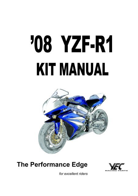
The Performance Edge - Yamaha-Racingparts.com
The Performance Edge - Yamaha-Racingparts.com
The Performance Edge - Yamaha-Racingparts.com
Create successful ePaper yourself
Turn your PDF publications into a flip-book with our unique Google optimized e-Paper software.
Introduction• Please understand that these parts are not covered by warranty.• <strong>The</strong> Manufacturer does not take any responsibility for problems caused by these parts.• <strong>The</strong>se kit parts are intended exclusively for racing purposes. You are strictly requested notto use them on public roads.• <strong>The</strong> specifications and usage methods of these kit parts along with the contents of thismanual are subject to change without notice for improvement.• This manual is intended for persons with knowledge and experience of motorcycles. Pleaserefer to the YZF-R1 service manual, which shall be published from YAMAHA MOTOR CO.LTD., for information on part assembly and maintenance.• <strong>The</strong> design of the YZF-R1 racing kit is based on YZF-R1, according to FIM racing rules, butthat does not mean the kit conforms to all <strong>com</strong>petitions.When used in races, riders must mount the YZF-R1 racing kit at their own discretion afterchecking the rules of <strong>com</strong>petition issued by the sponsor.Parts List Symbols• <strong>The</strong> star mark (*) means that the part is included in the kit set and is a genuine <strong>Yamaha</strong>part. <strong>The</strong>refore, you can easily purchase the part at any <strong>Yamaha</strong> part dealer whennecessary.• <strong>The</strong> circle mark (°) means that when needed, the individual part is sold separately to the kit set.No. PART No. PART NAME Q’TY REMARKS˚ 1 4C8-11181-70 GASKET, CYLINDER 3 t=0.30 mmHEAD 1* 2 5VY-11351-00 GASKET, CYLINDER 1 3* 3 4C8-11603-00 PISTON RING SET 124 5VY-1165A-01 BOLT, CONNECTING RODSPECIAL24* 5 93450-18157 CIRCLIP 24Symbol Marks<strong>The</strong> information necessary for correct handling and inspections and maintenance is shown withthe following symbol marks.CAUTION:NOTE:This indicates the possibility of injury or material damage occurring ifmishandled.This shows the method for correct operation and the points forinspection and maintenance.
1 Engine SpecificationsSpec SB STDisplacement 998 cm 3 ←Bore/stroke 77.0 mm/53.6 mm ←Maximum engine speed 13,900 rpm ←(limiter controlled speed)Compression ratio 12.7:1 ←Valve timing (event angle)INTEXT110°110°105°105°Squish height 0.775 mm ←Clearance between valveand pistonINT1.28 10°←EXT2.58 10°←Valve (tappet) clearanceINTEXT0.11mm – 0.20 mm0.26mm – 0.30 mm←←– 1 –
2 Kit Parts2-1 Engine Parts1. Maintenance Set (4C8-MAINT-71)Parts ListNo. PART No. PART NAME Q’TY REMARKS° 1 4C8-11181-70 GASKET, CYLINDER 3 t=0.30 mmHEAD 1* 2 5VY-11351-00 GASKET, CYLINDER 1 3* 3 4C8-11603-00 PISTON RING SET 124 5VY-1165A-01 BOLT, CONNECTING ROD 24SPECIAL* 5 93450-18157 CIRCLIP 24* 6 3P6-12129-00 SEAL, VALVE STEM OIL 2 24 INT* 7 4SV-12119-00 SEAL, VALVE STEM OIL 24 EXT° 8 4C8-13414-70 GASKET, STRAINER 3 (ANTI STICK TYPE)* 9 2D1-15451-10 GSKT., CRANKCASE 3 ACMCOVER 1° 10 5VY-15461-70 GSKT., CRANKCASE 3 CLUTCH (ANTI STICK TYPE)COVER 2° 11 5VY-15456-70 GASKET, COVER 1 3 PICK UP (ANTI STICK TYPE)* 12 4C8-15462-00 GSKT., CRANKCASE 3 BREATHERCOVER 313 90215-30233 WASHER, TONGUED 3 SPROCKET* 14 93102-40330 SEAL, OIL 3 DRIVE AXLE* 15 90110-06164 BOLT, HEX. SOCKET 9 MAIN AXLE– 2 –
2. Spark Plug Set (5FL-R045Q-70)Parts ListNo. PART No. PART NAME Q’TY REMARKS1 5FL-94700-70 PLUG, SPARK 4 NGK R0045Q-10NOTE:Since these spark plugs have a copper gasket, caution is needed during installation onthe following points.1. <strong>The</strong> tightening torque is 10 – 12 N·m (1.0 – 1.2 kgf·m).2. When not checking the torque, tighten by rotating through 30° after manualtightening in the case of new plugs. When reusing plugs, tighten by rotating through15°.(15˚)New gasket(30˚)Reused– 3 –
3. Head-gasket, Cylinder GasketParts ListNo. PART No. PART NAME Q’TY REMARKS1 4C8-11181-70 GASKET, CYLINDER 1 t=0.30 mmHEAD 12 4C8-11181-80 GASKET, CYLINDER 1 t=0.35 mmHEAD 13 5VY-11351-70 GASKET, CYLINDER 1 1 t=0.10 mm4 5VY-11351-80 GASKET, CYLINDER 1 1 t=0.15 mm<strong>The</strong>se parts are used to adjust the squish height and <strong>com</strong>pression ratio.<strong>The</strong>y should be installed in the direction, which enables the punched alpha-numeral “4C8” and“5VY” are visible.<strong>The</strong> standard head cylinder gasket thickness is 0.40 mm and the cylinder gasket thickness is0.20 mm.GASKET, CYLINDER HEADStamping locationGASKET, CYLINDERStamping location– 4 –
4. Piston Set (4C8-A1631-80)Parts ListNo. PART No. PART NAME Q’TY REMARKS1 4C8-11631-80 PISTON 4CAUTION:Must use the spark plug of KIT (5FL-R045Q-70) with kit piston.Experiencing trouble if you use the STD spark plug.Use the piston ring, piston pin, and circlip that are all STD ones.This set is made by MG Competition. For details of the specification, please check with MGCompetition.TEL +33 (0) 4 50 25 59 96FAX +33 (0) 4 50 25 59 98Web http://www.mg<strong>com</strong>petition.fr/– 5 –
5. High-lift CamshaftsParts ListNo. PART No. PART NAME Q’TY REMARKS1 4C8-12171-80 SHAFT, CAM 1 1 INT2 4C8-12181-80 SHAFT, CAM 2 1 EXT90105-070064C8-12176-0012To adjust the valve timing, use the oval holes of the standard cam sprocket.USE THESE OVAL HOLES FOR TIMING ADJUSTMENT.CAUTION:• When using this camshaft, use the valve spring set 4C8-A2110-80.• Make sure to align the valve timing when the camshaft is assembled. If otherwise, nointended performance can be expected and more over, the engine may be damaged.– 6 –
6. Valve Spring Set (4C8-A2110-80)Parts ListNo. PART No. PART NAME Q’TY REMARKS1 4C8-12113-80 SPRING, 1 8 For 4C8-12171-80 (INT)2 4C8-12114-80 SPRING, 2 8 For 4C8-12181-80 (EXT)CAUTION:When using this valve spring, use the camshafts 4C8-12171-80, and 4C8-12181-80.– 7 –
7. Funnel Set (4C8-A4460-80)Parts ListNo. PART No. PART NAME Q’TY REMARKS1 PLATE 22-1 FUNNEL, 1 4 L=45 mm2-2 FUNNEL, 1 4 L=60 mmNOTE:• <strong>The</strong> air cleaner case is kept fixed by the standard funnel. Remove this standardfunnel and install the plate in its destined place.• Before installation, apply a thin coat of grease to the threads of the funnel and plate.• For standard setting, use the shorter funnel (45 mm).Select the setting according to exhaust pipe specification, rider’s preference andtrack layout.This set is made by MG Competition. For details of the specification, please check with MGCompetition.TEL +33 (0) 4 50 25 59 96FAX +33 (0) 4 50 25 59 98Web http://www.mg<strong>com</strong>petition.fr/– 8 –
Selecting the FunnelIn addition to the funnel set in the KIT, the ycci system mounted on the STD vehicle can also beused. This is capable of being controlled (in operation timing etc.) by the use of YMS softwareac<strong>com</strong>panying KIT ECU. (ycci control is possible by using 2 kinds of basic control data (SBspec and ST spec) included in KIT ECU.– 9 –
8. Throttle Body Clamp Set (4C8-1351A-70)Parts ListNo. PART No. PART NAME Q’TY REMARKS* 1 90450-62002 HOSE CLAMP ASSY. 42 4C8-13573-70 BOLT, 1 23 4C8-1358A-70 ROD COMP. 2* 4 95307-05600 NUT, HEX 2LHRHThis part is used to enhance maintenance performance of the throttle body. Before using it, cutoff the protrusion for positioning bands at the cabjoint.Cut it off<strong>The</strong> part has a collar to prevent over-tightening. In normal cases, the part will not be tightenedtill it reaches to the collar. Just manually tighten it.Make sure to put a new band through a M5 x 0.8 tap before using it.– 10 –
9. AIS-plug Set (5VY-A4890-70)This plug set is used when the AIS (Air Induction System), an exhaust gas purifying system, isremoved.Parts ListNo. PART No. PART NAME Q’TY REMARKS1 5SL-1482L-70 PLATE, 2 2* 2 93608-16M16 PIN, DOWEL 43 90336-10020 PLUG, TAPER 1Installation1. Remove the hose attached to the cylinder head cover and the air cut-off valveac<strong>com</strong>panying the hose.2. Remove the cap fitted to the hose, remove the reed valve and plate from inside.3. Install the plate (5SL-1482L-70) in replacement of the cap. Apply liquid gasket to the plate.4. Remove the cylinder head cover and the four collars fitted to the cover. Install the PIN(93608-16M16).5. After removing the hose connected to the air filter casing form the air cut-off assembly,insert the PLUG (90336-10020) onto the side of the air filter casing to close the opening.– 11 –
– 12 –
10. Clutch Spring Set (4B1-A6330-70)Parts ListNo. PART No. PART NAME Q’TY REMARKS1 4B1-16334-70 SPRING, CLUTCH 6<strong>The</strong> kit spring has 10% more installation load than the STD spring.– 13 –
11. Slipper Clutch Setting Set (4C8-A6377-70)Parts ListNo. PART No. PART NAME Q’TY REMARKS° 1 4C8-16377-70 NUT, LOCK 1° 2 4B1-16391-70 SHIM 3a21cb42.4 – 43.0– 14 –
(Setting of back torque limiter of clutch).A clutch with a back torque limiter mechanism is installed in the YZF-R1 SP engines. <strong>The</strong>operation of the back torque limiter can be adjusted through adjusting: 2 the number of SHIMs(set up for the kit); a the number of springs; b the whole thickness of the clutch plate; and thestrength of c spring (set up for the kit) of the slipper clutch setting set.(Re<strong>com</strong>mended setting method)To begin with, the dimensions of the clutch are re-set to the standard values. (For details,please refer to the service manual published from YAMAHA MOTOR CO. LTD.When the 1 2 slipper clutch setting sets are to be installed, and the number of the SHIMs areto be three in stack, the setting may be carried out according to the standard.c Spring may be selected from either one of the kit parts or the standard parts. Spring load ofthe kit parts is designed to increase in 10% as <strong>com</strong>pared with that of the standard parts.– 15 –
When installing the kit parts, the back torque limiter tends not to be effective (Engine brakingbe<strong>com</strong>es more effective).When decreasing the number of SHIMs (standard setting is three) of slipper clutch setting set,the back torque limiter tends to be effective (Engine braking be<strong>com</strong>es less effective).Standard3 2 1 0effective(Engine braking be<strong>com</strong>esless effective)Further, when decreasing the number of a spring (the number of standard setting is three) totwo, the back torque limiter be<strong>com</strong>es effective (Engine braking be<strong>com</strong>es less effective).CAUTION:When decreasing the number ofa spring to two, the caution should be taken to surelyuse three pieces of SHIMs for the slipper clutch setting set. If its number being less thanthe above, the less load may be supported so as to exert serious influences on driving.Decreasing the number of a spring to one is not allowed.3 a springs,3 SHIMs3 a springs,2 SHIMs3 a springs,1 SHIM3 a springs,0 SHIMLoad2 a springs,3 SHIMsAs installedIn operationStroke– 16 –
12. Transmission GearParts ListNo. PART No. PART NAME Q'TY REMARKS1 4C8-17411-70-A AXLE, MAIN 1 AB1 4C8-17411-80-C AXLE, MAIN 1 C* 2 5VY-15163-00 HSG., BEARING 1* 3 93306-20652 BRG. 14 4C8-17151-70-A GEAR, 5TH PINION 1 A4 4C8-17151-80-B GEAR, 5TH PINION 1 BC5 4C8-17131-AA GEAR, 3RD PINION 1 AA5 4C8-17131-AB GEAR, 3RD PINION 1 AB5 4C8-17131-AC GEAR, 3RD PINION 1 AC5 4C8-17131-BB GEAR, 3RD PINION 1 BB5 4C8-17131-BA GEAR, 3RD PINION 1 BA5 4C8-17131-BC GEAR, 3RD PINION 1 BC5 4C8-17131-CC GEAR, 3RD PINION 1 CC6 4C8-17161-70-A GEAR, 6TH PINION 1 A6 4C8-17161-80-B GEAR, 6TH PINION 1 B6 4C8-17161-90-C GEAR, 6TH PINION 1 C7 4C8-17121-70-A GEAR, 2ND PINION 1 A7 4C8-17121-80-B GEAR, 2ND PINION 1 BC8 4C8-17402-70 DRIVE, AXLE ASSY. 1* 9 4C8-17421-00 AXLE, DRIVE 1* 10 93305-20605 BRG. 1* 11 5VY-17442-00 COLLAR, DISTANCE 112 4C8-17221-70-A GEAR, 2ND WHEEL 1 A12 4C8-17221-80-B GEAR, 2ND WHEEL 1 B12 4C8-17221-90-C GEAR, 2ND WHEEL 1 C13 4C8-17261-70-A GEAR, 6TH WHEEL 1 A13 4C8-17261-80-B GEAR, 6TH WHEEL 1 BC14 4C8-17241-70-A GEAR, 4TH WHEEL 1 A14 4C8-17241-80-B GEAR, 4TH WHEEL 1 B14 4C8-17241-90-C GEAR, 4TH WHEEL 1 C15 4C8-17231-70-A GEAR, 3RD WHEEL 1 A15 4C8-17231-80-B GEAR, 3RD WHEEL 1 B15 4C8-17231-90-C GEAR, 3RD WHEEL 1 C16 4C8-17251-70-A GEAR, 5TH WHEEL 1 A16 4C8-17251-80-B GEAR, 5TH WHEEL 1 B16 4C8-17251-90-C GEAR, 5TH WHEEL 1 C– 17 –
Parts ListNo. PART No. PART NAME Q'TY REMARKS17 4C8-17211-70-A GEAR, 1ST WHEEL 1 A17 4C8-17211-80-B GEAR, 1ST WHEEL 1 B17 4C8-17211-90-C GEAR, 1ST WHEEL 1 CSelect the gear after referring to the speed table and the ratio table.– 18 –
1716151314129810113241567CAUTION:This set contains modified gear ratios and docks <strong>com</strong>pared with the STD gearbox.Kit gears cannot use <strong>com</strong>bine standard gear.Gear ratiostd A B C1st 38/15 (2.533) 34/14 (2.429) 33/14 (2.357) 37/16 (2.313)2nd 33/16 (2.063) 32/15 (2.133) 32/16 (2.000) 31/16 (1.938)3rd 37/21 (1.762) 31/17 (1.824) 33/19 (1.737) 29/18 (1.611)4th 35/23 (1.522) 32/20 (1.600) 35/23 (1.522) 31/21 (1.476)5th 30/22 (1.364) 28/19 (1.474) 31/22 (1.409) 30/22 (1.364)6th 33/26 (1.269) 28/21 (1.333) 33/25 (1.320) 33/26 (1.269)– 19 –
YZF-R1 Mission ratioGEAR PLAN Ratio Pinion gear Wheel gearPart number <strong>The</strong> Stamp Part number <strong>The</strong> Stampnumberof teethnumberof teeth1st A 2.429 4C8-17411-70-A 14 R6C-AB 4C8-17211-70-A 34 R6C-1WAB 2.357 4C8-17411-70-A 14 R6C-AB 4C8-17211-80-B 33 R6C-1WBC 2.313 4C8-17411-80-C 16 R6C-C 4C8-17211-90-C 37 R6C-1WC2nd A 2.133 4C8-17121-70-A 15 R6C-2PAB 4C8-17221-70-A 32 R6C-2WBB 2.000 4C8-17121-80-B 16 R6C-2PCDE 4C8-17221-80-B 32 R6C-2WDC 1.938 4C8-17121-80-B 16 R6C-2PCDE 4C8-17221-90-C 31 R6C-2WE3rd A 1.824 See the 3- and 4- 17 R6C-3PA 4C8-17231-70-A 31 R6C-3WAB 1.737 speed pinion 19 R6C-3PBC 4C8-17231-80-B 33 R6C-3WCC 1.611 gear18 R6C-3PDE 4C8-17231-90-C 29 R6C-3WE4th A 1.600<strong>com</strong>binations20 R6C-4PA 4C8-17241-70-A 32 R6C-4WABtable.1.522 23 R6C-4PC 4C8-17241-80-B 35 R6C-4WCC 1.476 21 R6C-4PD 4C8-17241-90-C 31 R6C-4WD5th A 1.474 4C8-17151-70-A 19 R6C-5PA 4C8-17251-70-A 28 R6C-5WAB 1.409 4C8-17151-80-B 22 R6C-5PCD 4C8-17251-80-B 31 R6C-5WCC 1.364 4C8-17151-80-B 22 R6C-5PCD 4C8-17251-90-C 30 R6C-5WD6th A 1.333 4C8-17161-70-A 21 R6C-6PB 4C8-17261-70-A 28 R6C-6WBB 1.320 4C8-17161-80-B 25 R6C-6PC 4C8-17261-80-B 33 R6C-6WCDC 1.269 4C8-17161-90-C 26 R6C-6PD 4C8-17261-80-B 33 R6C-6WCDCAUTION:Make sure that the pinion and wheel gear are <strong>com</strong>bined for use according to the chartplan.<strong>The</strong>re is no interrelationship between the letter A, B, or C at the end of the part numberand the stamps on each gear. Take it into consideration in installation.– 20 –
3- and 4-Speed Pinion Gear Combinations TablePart number PLAN Mating wheel gear part numbers ’07 Kit part3rd 4th 3rd 4thnumbers4C8-17131-AA A A 4C8-17231-70-A 4C8-17241-70-A 4C8-17131-70-A4C8-17131-AB A B 4C8-17231-70-A 4C8-17241-80-B —4C8-17131-AC A C 4C8-17231-70-A 4C8-17241-90-C —4C8-17131-BB B B 4C8-17231-80-B 4C8-17241-80-B 4C8-17131-80-B4C8-17131-BA B A 4C8-17231-80-B 4C8-17241-70-A —4C8-17131-BC B C 4C8-17231-80-B 4C8-17241-90-C —4C8-17131-CC C C 4C8-17231-90-C 4C8-17241-90-C 4C8-17131-90-C– 21 –
YZF-R1 Speed ListEngine speed (rpm) 13900Tire radius (mm) 311 perimeter (m) 1.954Primary reduction ratio 43 65 1.512GEAR PLAN<strong>The</strong> numberof teethRatio17 17 17 16 17 16 17 16 17 15 16 17 15 16 15 16 15 16 15 15 15P W 41 42 43 41 44 42 45 43 46 41 44 47 42 45 43 46 44 47 45 46 47A 14 34 2.429 184.1 179.7 175.5 173.2 171.5 169.1 167.7 165.2 164.1 162.4 161.4 160.6 158.5 157.8 154.9 154.4 151.3 151.1 148.0 144.8 141.71stB 14 33 2.357 189.6 185.1 180.8 178.5 176.7 174.2 172.8 170.2 169.0 167.3 166.3 165.4 163.3 162.6 159.6 159.1 155.9 155.7 152.5 149.1 146.0C 16 37 2.313 193.3 188.7 184.3 181.9 180.1 177.6 176.1 173.5 172.3 170.6 169.5 168.6 166.5 165.8 162.6 162.2 158.9 158.7 155.4 152.0 148.8A 15 32 2.133 209.5 204.6 199.8 197.2 195.3 192.5 190.9 188.0 186.8 184.9 183.8 182.8 180.5 179.7 176.3 175.8 172.3 172.0 168.5 164.8 161.32ndB 16 32 2.000 223.5 218.2 213.1 210.4 208.3 205.4 203.6 200.6 199.2 197.2 196.0 195.0 192.5 191.7 188.0 187.5 183.8 183.5 179.7 175.8 172.0C 16 31 1.938 230.7 225.2 220.0 217.1 215.0 212.0 210.2 207.0 205.6 203.6 202.3 201.3 198.7 197.8 194.1 193.5 189.7 189.4 185.5 181.4 177.6A 17 31 1.824 245.1 239.3 233.7 230.7 228.4 225.2 223.3 220.0 218.5 216.3 215.0 213.8 211.1 210.2 206.2 205.6 201.6 201.3 197.1 192.8 188.73rdB 19 33 1.737 257.4 251.2 245.4 242.2 239.8 236.5 234.5 231.0 229.4 227.1 225.7 224.5 221.7 220.7 216.5 215.9 211.6 211.3 206.9 202.4 198.1C 18 29 1.611 277.5 270.9 264.6 261.1 258.5 254.9 252.8 249.0 247.3 244.8 243.3 242.0 239.0 237.9 233.4 232.8 228.1 227.8 223.1 218.2 213.6A 20 32 1.600 279.4 272.7 266.4 263.0 260.3 256.7 254.6 250.7 249.0 246.5 245.0 243.7 240.6 239.6 235.1 234.4 229.7 229.4 224.6 219.7 215.04thB 23 35 1.522 293.8 286.8 280.1 276.5 273.7 269.9 267.6 263.6 261.8 259.2 257.6 256.3 253.0 251.9 247.1 246.4 241.5 241.2 236.2 231.0 226.1C 21 31 1.476 302.8 295.6 288.7 285.0 282.2 278.2 275.9 271.8 269.9 267.2 265.6 264.2 260.8 259.7 254.8 254.0 249.0 248.6 243.4 238.2 233.1A 19 28 1.474 303.3 296.1 289.2 285.5 282.7 278.7 276.4 272.2 270.4 267.6 266.0 264.6 261.3 260.1 255.2 254.5 249.4 249.0 243.9 238.6 233.55thB 22 31 1.409 317.2 309.7 302.5 298.6 295.6 291.5 289.0 284.7 282.8 279.9 278.2 276.7 273.3 272.0 266.9 266.1 260.8 260.5 255.0 249.5 244.2C 22 30 1.364 327.8 320.0 312.6 308.5 305.5 301.2 298.7 294.2 292.2 289.2 287.5 286.0 282.4 281.1 275.8 275.0 269.5 269.1 263.5 257.8 252.3A 21 28 1.333 335.3 327.3 319.7 315.5 312.4 308.0 305.5 300.9 298.8 295.8 294.0 292.5 288.8 287.5 282.1 281.2 275.7 275.3 269.5 263.7 258.16thB 25 33 1.320 338.7 330.6 322.9 318.7 315.6 311.1 308.5 303.9 301.8 298.8 297.0 295.4 291.7 290.4 284.9 284.1 278.4 278.0 272.2 266.3 260.7C 26 33 1.269 352.2 343.8 335.8 331.5 328.2 323.6 320.9 316.1 313.9 310.8 308.9 307.2 303.4 302.0 296.3 295.4 289.6 289.2 283.1 277.0 271.1• Values in the speed table may vary slightly according to tire manufacturer and size.• Select after referring to the value in the speed table.EnginesideWheelsideSecondaryreductionratio(Sprocket)Speed(km/h)– 22 –
13. Mission Maintenance Set (4C8-A7000-70)Parts ListNo. PART No. PART NAME Q'TY REMARKS* 21 90387-28003 COLLAR 3* 22 90209-25011 WASHER 6* 23 93440-28184 CIRCLIP 10* 24 90387-25007 COLLAR 3* 25 90214-25004 WASHER, CLAW 3* 26 90214-25003 WASHER, CLAW 3* 27 90387-31003 COLLAR 3* 28 90209-28008 WASHER 9* 29 93440-31187 CIRCLIP 15* 30 90387-28004 COLLAR 6* 31 90214-29002 WASHER, CLAW 3* 32 90214-28002 WASHER, CLAW 3* 33 90387-25008 COLLAR 3* 34 93102-40330 SEAL, OIL 3* 35 93440-62032 CIRCLIP 5* 36 90201-257H0 WASHER, PLAIN 3* 37 93306-27208 BRG. 338 5VY-17166-00 BRG., 2 3– 23 –
38363329282928273032313028293534212223232224252637– 24 –
Transmission Assembly<strong>The</strong> seal side should face outward (one sideseal bearing) and press in the bearing cup allthe way into the case until it touches bottom.Apply molybdenum oil to inside of diameter.After assembly, it should rotate smoothly.Apply molybdenum oil to the inside diameterand end. After assembly, it should rotatesmoothly.Apply molybdenum oil to teeth of spline.After assembly, it should slide smoothly.Points to be careful of the oil seal assembly<strong>The</strong> convex part on the oil seal should beput into the case groove vertically so thatthe oil seal does not fall over and is tightlyfit into the bearing cup of the bearing.(Apply grease to the lip.)Matching markMatching mark<strong>The</strong> seal side should face outward (oneside seal bearing) and assembled towardthe case right side edge.NOTE:• Always use a new circlip.• Do not mistake the washer and circlip directions.(See drawing below.)WasherWasherCirclip(Direction notapplicable)ShaftWasherGearShaft<strong>Edge</strong>Portion RPosition the center of the abutment jointof the circlip right with the spline threads.Detail of installation of washerMatching markMatching markWasherRotate washer so that its teeth meet axlesplineteeth on the axle, and then lock withwasher’s claw.Assemble washer with putting togethertheir matching mark.Detail of installation of circlipWasher<strong>Edge</strong>Portion RShaftDetail of installation of washer– 25 –
14. Gear, 5th Wheel Special (4C8-172E1-70)Parts ListNo. PART No. PART NAME Q'TY REMARKS1 4C8-172E1-70 GEAR, 5TH WHEEL 1SPECIALKit Axle MainGear 5th Wheel SpecialKit Gear 1st Wheel• When using only the 1st gear kit parts, change the 5th wheel to this part to use theremaining STD gear as it is.• <strong>The</strong> ratio of the 5th gear is the same as STD.• Select the 1st kit gear after referring to the speed table and the ratio table.– 26 –
15. Drive SprocketsParts ListNo. PART No. PART NAME Q’TY REMARKS1 4XV-17460-75 SPROCKET, DRIVE 1 15T, 520SIZE2 4XV-17460-76 SPROCKET, DRIVE 1 16T, 520SIZE3 4XV-17460-77 SPROCKET, DRIVE 1 17T, 520SIZECAUTION:When using this drive sprocket, use the sprocket nut of the kit.– 27 –
16. Sprocket Nut Set (4C8-A7463-70)Parts ListNo. PART No. PART NAME Q’TY REMARKS1 4C8-17463-70 NUT 12 90215-30233 WASHER, LOCK 1CAUTION:When using this sprocket nut, use the drive sprocket of the kit.– 28 –
17. Rotor Assembly (5VY-81450-71)Parts ListNo. PART No. PART NAME Q'TY REMARKS1 5VY-81450-70 ROTOR ASSY. 12 2D1-15451-10 GASKET, CRANKCASE 1COVER 1* 3 90201-066F0 WASHER, PLAIN 4* 4 90201-08087 WASHER, PLAIN 3DIRECTION OF ONE-WAY CLUTCH ROTATIONINSTALL STD PARTSThis rotor has narrowed width than the STD rotor, aiming at reduced inertial mass and frictionloss.For the stator coil, use standard one.– 29 –
NOTE:• <strong>The</strong> rotor and starter clutch are integrated. Use a standard starter clutch.• After the installation of the starter clutch, check for direction of rotation.• When installing the cover integrated with the stator coil, use the ac<strong>com</strong>panyinggasket and washer.• To fasten the cover, first tighten M8 bolts (3 bolts) to 22.0 N•m and then theremaining M6 bolt to 10.0 N•m.AFTER TIGHTENING THE 3 M8 BOLTS TO 22 Nm,TIGHTEN THE OTHER (M6) BOLTS.– 30 –
18. ECU Set (4C8-8591A-80)Parts ListNo. PART No. PART NAME Q'TY REMARKS1 4C8-8591A-80 ECU 12 13S-2818Y-70 CD 1 YMS, MANUAL• Use of this set and a wire harness included in the kit enables regulation (or setting) of fuelinjection and ignition timing, etc.• For details as to how to regulate (or set) fuel injection and ignition timings, etc., refer to theFI matching system manual in the CD-ROM that <strong>com</strong>es with the set.• <strong>The</strong>re are two types of basic control data for the ECU included in this set: SB (Super Bike)and ST (Stock Sports). <strong>The</strong>y can be switched over and vice versa. To make it in the STspecification, just remove two couplers located at the lower left of the kit harness fuel tank.(See the figure below.)SB specification: Kit cam shaft and *Re<strong>com</strong>mended mufflerST specification: *Re<strong>com</strong>mended muffler* Re<strong>com</strong>mended mufflerMade by Akrapovic (For details of the specification, please access the website.)Web http://www.akrapovic-exhaust.<strong>com</strong>CAUTION:Do not use the ECU of this set for any other assembly than the one below.ECUWIRE HARNESS ASSY. THROTTLE BODY ASSY.2007 Models 4C8-8591A-70 4C8-82590-70 4C8-13750-002008 Models 4C8-8591A-80 4C8-82590-80 4C8-13750-20– 31 –
19. Cable Interface (13S-8533A-70)Parts ListNo. PART No. PART NAME Q'TY REMARKS1 13S-8533A-70 CABLE, INTERFACE 1 USB2 13S-N81CD-70 8cm CD 1 USB driver• This cable connects the kit wire harness to the personal <strong>com</strong>puter on which YEC FIMatching System (YMS) is installed.• Please see the YMS manual for instructions on how to use YMS.• When connecting the cable to the PC for the first time, it is necessary to install the USBdriver. Refer to the USB Driver Installation Manual provided on the 8 cm CD for details onhow to install the USB driver.• <strong>The</strong> product vendor ID and product ID are provided by the Hamamatsu TOA Electronics,Inc.Vendor ID: 6837Product ID: 9001– 32 –
Diagnosis Functions• Use of the ECU in the kit and the harness allows functioning of the following codes in theSTD diagnosis.* YMS-Monitor: YEC FI Matching System also allows functioning of the code shown below.CODE Contents *YMS-Monitor01 Throttle sensor TPS 1(deg)02 Atmospheric pressure sensor Atmospheric (kPa)03 Intake pressure sensor 1 Intake Air (kPa)05 Intake temperature sensor Air Temp. (°C)06 Water temperature sensor Water Temp. (°C)07 Vehicle speed sensor Speed Signal (--)08 Overturn sensor Lean Angle Signal(V)09 Monitor voltage System Voltage (V)13 Throttle sensor 2 TPS 2 (deg)14 Accelerator sensor 1 APS 1 (deg)15 Accelerator sensor 2 APS 2 (deg)21 Neutral switch Neutral SW30 Ignition coil #1 —31 Ignition coil #2 —32 Ignition coil #3 —33 Ignition coil #4 —36 Injector (primary) #1 —37 Injector (primary) #2 —38 Injector (primary) #3 —39 Injector (primary) #4 —50 Main relay —70 Program version —– 33 –
Self-Diagnosis Functions• <strong>The</strong> ECU and harness in the kit provide the functions for the following codes of standardself-diagnosis:CODEDescription00 All functions normally.11 Cam angle sensor malfunctions.12 Crank angle sensor malfunctions.13 Intake pressure sensor malfunctions (open circuit / short circuit).14 Intake pressure sensor malfunctions (piping system).15 Throttle opening sensor malfunctions (open circuit / short circuit / ETV).20 Intake pressure sensor or atmospheric pressure sensor malfunctions.21 Water temperature sensor malfunctions (open circuit / short circuit).22 Intake temperature sensor malfunctions (open circuit / short circuit).23 Atmospheric pressure sensor malfunctions (open circuit / short circuit).33 Ignition coil #1 malfunctions (open circuit).34 Ignition coil #2 malfunctions (open circuit).35 Ignition coil #3 malfunctions (open circuit).36 Ignition coil #4 malfunctions (open circuit).39 Injector (primary) malfunctions (open circuit).43 Battery voltage monitor malfunctions (power source for fuel system).46 Power source for vehicle malfunctions.59 Accelerator opening sensor malfunctions (open circuit / short circuit).60 Throttle motor malfunctions (drive system).– 34 –
20. Wire Harness Set (4C8-F2590-80)Parts ListNo. PART No. PART NAME Q'TY REMARKS1 4C8-82590-80 WIRE HARNESS ASSY. 1° 2 5FL-83976-70 SWITCH ASSY. 1 MAIN SWITCH* 3 5GF-83976-00 SW. HANDLE 1 1 PIT ROAD LIMITER4 2C0-82509-70 WIRE SUB-LEAD 15 4C8-82188-70 RESISTOR ASSY. 1CAUTION:• Do not remove the AC generator but leave it to function. Use on the battery alone willmake the machine unable to run in a short time.• <strong>The</strong> wire harness will not function if it is not assembled with the ECU (4C8-8591A-80)of the kit.• <strong>The</strong> switches (2 types) supplied in this set enable the main switch and pit road limiter to beused. (See diagram 1.) <strong>The</strong> switch ac<strong>com</strong>panying the assembly, functions as the mainswitch.(Diagram 1)Main switchPit roadlimiterEngine stopswitchStarterswitch– 35 –
• <strong>The</strong> switch installed to the STD machine may be used as is. (See diagram 2.)• Map select switches Map 1 and Map 2 of the YMS “Comp. FUEL.”CAUTION:When switching to Map 1 or Map 2 using “Map Select” while riding, check that properriding is possible even when using either map.(Digram 2)Pit roadlimiterONOFFNot usedMap selectLo → Map 1Hi → Map 2Pit roadlimiterON ONPUSH=OFFShifter switch*Use 5FL-83976-70SWITCH ASSYsupplied in thispackage as a mainswitch.Engine stopswitchStarterswitch• <strong>The</strong> shifter switch function can be used by <strong>com</strong>bining the harness and kit ECU.1 To use the STD switch (left side) to function as the shifter switch, connect the wire subleadthat was packaged with this set to the terminal that is normally connected to the leftside horn. (See diagram 3.) However, if the resistor assembly that was packaged with theset is not installed, there is the possibility that the shifter switch will operate incorrectly inrainy weather. <strong>The</strong> resistor assembly is installed to the 2-pin black coupler at the tail.(See diagram 4.)CAUTION:Do not bend the resistor assembly. It will cease to function if it is bent.2Install the switch to the 2-pin black coupler underneath the fuel tank. Turning the switchON cuts the ignition.(Diagram 3) (Diagram 4) 5• This harness has a coupler that connects to the 2D made data logger.For details of the specifications of the data logger, please access the website.Web http://www.2d-kit-system.<strong>com</strong>/– 36 –
21. Headlight Harness Set (4C8-F4350-70)Parts ListNo. PART No. PART NAME Q’TY REMARKS1 4C8-84359-70 CORD, HEAD LIGHT 1* 2 5JJ-81950-20 RELAY ASSY. 2* 3 5GF-83976-00 SW., HANDLE 1 1 For emergency* 4 5RT-83963-00 SW., HANDLE 3 1 On-off, kill5 4C8-84312-70 CORD ASSY. 1This set is used in endurance races in <strong>com</strong>bination with the kit harness for turning on the STDheadlights and taillights.It assumes that the standard headlights and taillights are used.<strong>The</strong> 2-system circuit is provided to allow the other bulb to light up when one is broken.<strong>The</strong> headlight and taillight circuits are independent of one another. If the headlight is broken,the taillight will not go out.<strong>The</strong> switch (5GF-83976-00) lights only the rear light.– 37 –
2-2 Chassis Parts22. Oil Catcher Tank Set (4C8-C1707-70)Parts ListNo. PART No. PART NAME Q'TY REMARKS1 4C8-21707-70 OIL TANK COMP. 1* 2 90450-25037 HOSE CLAMP ASSY. 33 4C8-15373-70 PIPE, BREATHER 1 14 4C8-15393-70 PIPE, BREATHER 2 1* 5 90480-11006 GROMMET 1* 6 90387-062N2 COLLAR 1* 7 90111-06051 BOLT, HEX. SOCKET 1BUTTON* 8 92907-06200 WASHER, PLAIN 1* 9 95707-06500 NUT, FLG. 1* 10 90464-20237 CLAMP 1* 11 90467-14015 CLIP 1<strong>The</strong> capacity of this tank is 550cc.– 38 –
WIRE HARNESSAIR FILTER CASEFRAME– 39 –
23. Front Fork Spring SetParts List (4C8-C3141-70)No. PART No. PART NAME Q’TY REMARKS1 4C8-23141-70 SPRG., 1 2 9.31 N/mm (0.95 kgf/mm)Identification line (1 line)* 2 5PW-23118-00 SPACER 2* 3 4XV-23142-00 SEAT, SPRG. UPPER 2Parts List (4C8-C3141-80)No. PART No. PART NAME Q’TY REMARKS1 4C8-23141-80 SPRG., 1 2 9.8 N/mm (1.00 kgf/mm)Identification line (2 lines)* 2 5PW-23118-00 SPACER 2* 3 4XV-23142-00 SEAT, SPRG. UPPER 2NOTE:• Please build in the spacer and the spring seat of the attachment detaching the STDspacer when the kit spring is set up.• <strong>The</strong> spring rate is identified by the number of lines on its end.Basic setting (Standard front fork + Kit spring)Initial adjuster13 mm (up to top end)Oil level101 mm (when <strong>com</strong>pressed as far as possible)Suspension oil <strong>Yamaha</strong> Suspension Oil 01Click positionRebounding : Backed 10 notches from thestrongest positionCompressing : Backed 10 notches from thestrongest positionSTDKIT23Replace1– 40 –
24. Seat Cushion (13S-24713-70)Parts ListNo. PART No. PART NAME Q’TY REMARKS1 13S-24713-70 CUSHION SEAT 1Anti slip seat.Cut to any size for use.– 41 –
25. Front Spare Wheel ASS’Y (4C8-25100-70)Parts ListNo. PART No. PART NAME Q’TY REMARKS* 1 5VY-25168-00 WHEEL, CAST 1 MAT BLACK* 2 4XV-25117-00 SPACER, BEARING 1* 3 93306-07208 BEARING 2* 4 93106-28043 SEAL, OIL 2* 5 93900-00030 VALVE, RIM 1This ASS’Y is build up with bearings and spacer, air-valve.– 42 –
26. Rear Spare Wheel ASS’Y (4C8-25300-70)Parts ListNo. PART No. PART NAME Q’TY REMARKS* 1 5VY-25338-00 WHEEL, CAST 1 MAT BLACK* 2 93306-20531 BEARING 1* 3 93106-40013 SEAL, OIL 1* 4 93317-43580 BEARING 1* 5 93420-61M07 CIRCLIP 1* 6 5PW-25317-00 SPACER, BEARING 1* 7 4XV-25383-00 COLLAR, WHEEL SHAFT 1* 8 93900-00030 VALVE, RIM 1This ASS’Y is build up with bearings and spacer, air-valve.– 43 –
27. Throttle Set (4C8-C6300-70)Parts ListNo. PART No. PART NAME Q’TY REMARKS° 1 2C0-26281-70 CAP, GRIP UPPER 1* 2 5FL-26282-00 CAP, GRIP UNDER 1° 3 5SL-26243-71 TUBE, GUIDE 1 Linear type° 4 2C0-26391-70 CLIP, WIRE 1 1° 5 4C8-26311-70 WIRE, THROTTLE 1 2 Grip side: Common usefor pulling back.° 6 4C8-26313-70 WIRE, THROTTLE 3 2 Engine side: Commonuse for pulling back.° 7 2C0-26261-70 CYLINDER 2° 8 5FL-26244-70 SLIDER 29 2C0-2639E-70 PROTECTOR 2* 10 90201-261L1 WASHER, PLAIN 1* 11 91314-05020 BOLT, HEX. SOCKET 2HEAD* 12 91314-05008 BOLT, HEX. SOCKETHEAD1121045789631211Machining off the boss.Scrap away CAP, GRIP UPPERof the kit as shown above– 44 –
28. Throttle Set (4C8-C6300-80)Parts ListNo. PART No. PART NAME Q'TY REMARKS° 1 2C0-26281-70 CAP, GRIP UPPER 1* 2 5FL-26282-00 CAP, GRIP UNDER 1° 3 5SL-26243-71 TUBE, GUIDE 1 Linear type° 4 2C0-26391-70 CLIP, WIRE 1 1° 5 4C8-26302-70 THROTTLE WIRE ASSY. 2 Common use for pullingback.* 6 90201-261L1 WASHER, PLAIN 1* 7 91314-05020 BOLT, HEX. SOCKETHEAD2* 8 91314-05008 BOLT, HEX. SOCKETHEAD186453127Machining off the boss.Scrap away CAP, GRIP UPPER of the kit as shown above– 45 –
29. Tube Guide (5VY-26243-80)Parts ListNo. PART No. PART NAME Q'TY REMARKS1 5VY-26243-80 TUBE, GUIDE 1 Progressive typeAbout the Throttle Tube Guide SpecificationsAs shown below, the operating angle of the throttle grip up to when the throttle body opening is25% is the same as STD, and the operating angle of the throttle grip when the throttle is fullyopened is 58°.According to this, the easy operability has been realized through controlling the throttle bodyopening at an initial stage of the throttle grip operation, the stage of which is difficult to control,as that of the STD, while keeping the operability (full opening performance) during racing.Throttle body opening100%5SL-715VY-70STD50%25%0%52°58°69°Throttle grip operation angle– 46 –
3 Tightening Torque ListEngineTo be tightened Part No. Part Name Thread dia.xpitchPlug for sanddrain holeInstall SPARKPLUG90340-18002 PLUG,STRAIGHTSCREW5FL-94700-70PLUG,SPARKTighteningtorque N•m(kgf•m)Q’tyRemarksM18 x 1.5 42±4 (4.3±0.4) 3 APPLY LOCK-ING AGENT(LOCKTITE®)TO BOTHSCREWTHREAD ANDTAPERED POR-TION.M10S x 1.0 10 – 12(1.0 – 1.2)4 FOR DETAILS,SEE page 3.Tighten HEAD 90176-10075 NUT M10 x 1.25 TURN OF NUTMETHOD:AXIAL FORCETARGETVALUE OF 47kN± 5kN WITHSNUG TORQUEOF 42 (4.2) RETIGHTEN TOAN ANGLE OF90 ± 5°.Tighten HEAD 90179-10414 NUT M10 x 1.25 TURN OF NUTMETHOD:AXIAL FORCETARGETVALUE OF 47kN± 5kN WITHSNUG TORQUEOF 33 (3.3) RETIGHTEN TOAN ANGLE OF70 ±5°.2 FOR DETAILS,SEE page 58.8 FOR DETAILS,SEE page 58.Tighten HEAD 90110-06212 BOLT,HEXAGONSOCKETHEADM6 x 1.0 12±2 (1.2±0.2) 2CAP x HEAD 90105-06027 BOLT,FLANGETighten HEADCOVEREmbedded inHEAD(Install EX.PIPE)M6 x 1.0 10±2 (1.0±0.2) 20 APPLY OIL TOSCREWTHREAD ANDBEARING SUR-FACE (DURINGMACHINING,TOO)90109-066F0 BOLT M6 x 1.0 12±2 (1.2±0.2) 695612-08625 BOLT,STUDM8 x 1.25 15±2 (1.5±0.2) 8– 47 –
EngineTo be tightened Part No. Part Name Thread dia.xpitchAI CAP 90110-06175 BOLT,HEXAGONSOCKETHEADSPROCKET x 90105-07006 BOLT,CAMSHAFTFLANGEHEAD X JOINT, 91312-06016 BOLT,HEXAGONCARBURETORSOCKETHEADCON RODSPROCKET,CRANKCAM CHAIN,TENSIONER5VY-11654-015VY-1165A-01(Long bolt)BOLT,CON-RODBIG END90105-10290 BOLT,FLANGE90110-06106 BOLT,HEXAGONSOCKETHEADInstall PIPE, 1 90110-06161 BOLT,HEXAGONSOCKETHEADInstall PIPE, 4 90110-06161 BOLT,HEXAGONSOCKETHEADInstall PIPE, 4 90110-06174 BOLT,HEXAGONSOCKETHEADTighten HOSE 90450-3500190450-32001Install PUMPDRIVINGSPROCKETHOSECLAMPASSY90105-06066 BOLT,FLANGEM6 x 1.0 10±2 (1.0±0.2) 4M7 x 1.0 24±2 (2.4±0.2) 4M6 x 1.0 10±2 (1.0±0.2) 7M8 x 0.75Tighteningtorque N•m(kgf•m)TURN OF NUTMETHOD:RETIGHTEN TOSNUG TORQUEOF 19.6 (2.0) ANGLE OF 150± 5°.88APPLY “SUM-ICO MORIASSEMBLY OIL150”.M10 x 1.25 60±5 (6.0±0.5) 1 APPLY OIL TOSCREWTHREAD.M6X1.0 10±2 (1.0±0.2) 2M6 x 1.0 10±2 (1.0±0.2) 1M6 x 1.0 10±2 (1.0±0.2) 1 WATER PUMPSIDEM6 x 1.0 10±2 (1.0±0.2) 1 RUBBERMOUNT SIDEREF. 1. 5 – 2.5(0.15 – 0.25)11BREAKAGEOCCURS AT 4 –5N•m.M6 x 1.0 15±2 (1.5±0.2) 1 DEGREASESCREWTHREAD.Install PUMP 90110-06167 BOLT, M6 x 1.0 12±2 (1.2±0.2) 2FLANGETHERMOSTAT 90176-06014 CAP, NUT M6 x 1.0 10±2 (1.0±0.2) 2ASSYInstall PIPE,5 90110-06168 BOLT,HEXAGONSOCKETHEADM6 x 1.0 10±2 (1.0±0.2) 1Q’tyRemarks– 48 –
EngineTo be tightened Part No. Part Name Thread dia.xpitchInstall OILCOOLERTighten DRAINBOLTInstall PIPE, OIL1InstallHOUSING,STRAINERInstall PIPEHOLDERTightenCLEANINGBOLT, UNIONInstall OILCLEANERASSYInstall COVER,STRAINERInstallTHROTTLEWIREJOINT ASSY XTHROTTLEBODYTHROTTLE XFUNNELAIR FILTERCASE XFUNNEL(for SUPPORT)5EB-12822-00BOLT,UNIONM20 x 1.5 63±3 (6.3±0.3) 1 APPLY OIL TOSCREWTHREAD ANDBEARING SUR-FACE.90340-14132 PLUG M14 x 1.5 43±4 (4.3±0.4) 190110-06161 BOLT,HEXAGONSOCKETHEAD90110-06173 BOLT,HEXAGONSOCKETHEAD90110-06182 BOLT,HEXAGONSOCKETHEAD90401-20145 BOLT,UNION5GH-13440-20OILCLEANERASSY91312-06025 BOLT,HEXAGONSOCKETHEAD90110-05032 BOLT,HEXAGONSOCKETHEAD90450-62002 HOSECLAMPM6X1.0 10±2 (1.0±0.2) 2M6X1.0 10±2 (1.0±0.2) 3M6X1.0 10±2 (1.0±0.2) 3 HOLDER X 2 +OIL RETURN X 1M20 x 1.5 70±5 (7.0±0.5) 1M20 x 1.5 17±2 (1.7±0.2) 1 APPLY GREASETO O-RING.M6 x 1.0 12±2 (1.2±0.2) 14M5 x 0.8 4±0.5 (0.4±0.05) 2M5 x 0.8 3±0.5 (0.3±0.05) 490109-06184 BOLT M6 x 1.0 6±1 (0.5±0.1) 690159-05035 SCREWWITHWASHERUPPER COVER 98902-05020 SCREW,BINDINGHEADTighteningtorque N•m(kgf•m)M5 x 0.8 2.5±0.5(0.25±0.05)M5 x 0.8 2.0±0.5(0.2±0.05)Q’tyRemarks2 TIGHTENAFTER THROT-TLE X FUNNEL.9 (TARGETVALUE OF2.0N•m)– 49 –
EngineTo be tightened Part No. Part Name Thread dia.xpitchNUT, RING XCYLINDERHEADEX. PIPE(DIFFUSER) XMUFFLEREX. PIPE COMPX EXT. VALVEASSYEXT. VALVEASSY XHOUSINGPULLEY X ARMSHAFTInstall WIREBRACKETInstall VALVEPROTECTORInstall EX. PIPEASSYInstall WIREPULLEYDOUBLE NUTCATALYSTCONVERTER XREAR FRAMECATALYSTCONVERTER XBRACKETSTAYEX. PIPE ASSYX CATALYSTCONVERTERInstallSERVOMOTORMUFFLER XREAR FRAME90179 x0841090105-08063 BOLT,FLANGE90110-06110 BOLT,HEXAGONSOCKETHEAD90110-06110 BOLT,HEXAGONSOCKETHEADNUT M8 x 1.25 20±2 (2.0±0.2) 8M8 x 1.25 20±2 (2.0±0.2) 2M6 x 1.0 12±2 (1.2±0.2) 5M6 x 1.0 10±2 (1.0±0.2) 190179-06063 NUT M6 x 1.0 6.5±1.5(0.65±0.15)90110-06110 BOLT,HEXAGONSOCKETHEAD90110-06110 BOLT,HEXAGONSOCKETHEAD95812-08040 BOLT,FLANGE4C8-1133E-4C8-1133F-WIRE,PULLEY,1WIRE,PULLEY,290111-08058 BOLT,BUTTONHEAD90111-08021 BOLT,BUTTONHEAD95814-08030 BOLT,FLANGE95022-06020 BOLT,FLANGE(SMALLHEAD)95814-08045 BOLT,FLANGETighteningtorque N•m(kgf•m)M6 x 1.0 10±2 (1.0±0.2) 1M6 x 1.0 10±2 (1.0±0.2) 2M8 x 1.25 20±2 (2.0±0.2) 1M6 x 1.0 5 – 7 (0.5 – 0.7) 1M8 x 1.25 20±2 (2.0±0.2) 1M8 x 1.25 20±2 (2.0±0.2) 1M8 x 1.25 20±2 (2.0±0.2) 1M6 x 1.0 5 – 7 (0.5 – 0.7) 2M8 x 1.25 18 – 28(1.8 – 2.8)Q’ty112Remarks– 50 –
EngineTo be tightened Part No. Part Name Thread dia.xpitchInstallMUFFLERPROTECTORInstallCATALYSTCONVERTERPROTECTORImplant inCRANKCASE 1CRANKCASE 1x CRANKCASE2CRANKCASE 1x CRANKCASE2CRANKCASE 1x CRANKCASE2CRANKCASE 1x CRANKCASE2CRANKCASE 1x CRANKCASE2Install COVER,CRANKCASE 1(15411)Install COVER,CRANKCASE 1(15411)Install COVER,CHAINCASE(15418)Install COVER,CRANK 3(15431)90111-06038 BOLT,HEXAGONSOCKETHEAD92014-06012 BOLT,BUTTONHEAD90116-1003290116-10023BOLT,STUD90119-09003 BOLT,HEXAGONWITHWASHERM6 x 1.0 10±2 (1.0±0.2) 4M6 x 1.0 6.5±1.5(0.65±0.15)M10 x 1.25M9 x 1.258 TARGETEDAT 6 – 9 (0.8TARGETED AT0.6 – 0.9)FOR DETAILS,SEE page 59473APPLY OIL TOBOTH SCREWTHREAD ANDBEARING SUR-FACE. CON-TROL TORQUE.10 APPLY OIL TOBOTH SCREWTHREAD ANDBEARING.90109-06100 BOLT M6 x 1.0 10±2 (1.0±0.2) 2 APPLY OIL TOBOTH SCREWTHREAD ANDBEARING.95812-060BOLT,FLANGEM6 x 1.0 10±2 (1.0±0.2) 8 APPLY OIL TOBOTH SCREWTHREAD ANDBEARING.90105-08101 BOLT M8 x 1.25 24±2 (2.4±0.2) 1 APPLY OIL TOBEARING SUR-FACE.95812-0800BOLT,FLANGEM8 x 1.25 24±2 (2.4±0.2) 5 APPLY OIL TOBOTH SCREWTHREAD ANDBEARING.90109-06031 BOLT M6 x 1.0 12±2 (1.2±0.2) 4 ACM COVER90110-08068 BOLT,HEXAGONSOCKETHEAD90110-06255 BOLT,HEXAGONSOCKETHEADTighteningtorque N•m(kgf•m)Q’tyRemarksM8 x 1.25 22±2 (2.2±0.2) 3 ACM COVERM6 x 1.0 12±2 (1.2±0.2) 3 DRIVESPROCKETCOVER90109-06014 BOLT M6 x 1.0 10±2 (1.0±0.2) 3 LEFT COVER,CRANK– 51 –
EngineTo be tightened Part No. Part Name Thread dia. Tightening Q’ty Remarksx torque N•mpitch (kgf•m)Install COVER, 90109-06016 BOLT M6 x 1.0 12±2 (1.2±0.2) 7 CLUTCH COVERCRANKCASE 2(15421)Install COVER, 90110-06112 BOLT M6 x 1.0 12±2 (1.2±0.2) 1 CLUTCH COVERCRANKCASE 2(15421)Install COVER1(15416)90109-06014 BOLT M6 x 1.0 12±2 (1.2±0.2) 6 CAM CHAINCOVERInstall COVER(15413)90109-06015 BOLT M6 x 1.0 12±2 (1.2±0.2) 4 BREATHERCOVERInstall PLATE, 90110-06182 BOLT, M6 x 1.0 10±2 (1.0±0.2) 3HEXAGONBREATHERSOCKETHEADInstall PLATE 90110-06277 BOLT, M6 x 1.0 12±2 (1.2±0.2) 1HEXAGON(15113)SOCKETHEADInstall PLATE 90110-06276 BOLT, M6 x 1.0 12±2 (1.2±0.2) 1HEXAGON(15113)SOCKETHEADInstall PLUG to 92014-08016 BOLT, M8 x 1.25 15±2 (1.5±0.2) 1 CHECK TIMING.BUTTONCOVER 1HEADInstall PLUG toCOVER 1Install PLUG toCOVER C/C2MAIN GALLERY1, OIL RETURNPLUGMAIN GALLERY2OIL RETURNPIPEOIL RETURNPLUG90340-32004 PLUG,STRAIGHTSCREW3F9-15362-0036Y-15189-004H7-15189-00PLUG, OILLEVEL90110-06161 BOLT,HEXAGONSOCKETHEAD90340-12003 PLUG,STRAIGHTSCREWACM LEAD 90105-06078 BOLT,FLANGEM32X1.5CLOSE CON-TACT WITHBEARING SUR-FACEM20 x 1.5 1.5±0.5(0.15±0.05)1 FOR CRANKROTATION1 TAKE CARENOT TO OVER-TIGHTEN.PLUG M16 x 1.5 8±2 (0.8±0.2) 3 TAKE CARENOT TO OVER-TIGHTEN.PLUG M20 x 1.5 8±2 (0.8±0.2) 1 TAKE CARENOT TO OVER-TIGHTEN.M6 x 1.0 10±2 (1.0±0.2) 2M12 x 1.0 24±3 (2.4±0.3) 2M6 x 1.0 10±2 (1.0±0.2) 1Install STATOR 90149-06067 SCREW M6 x 1.0 14±2 (1.4±0.2) 3 TORQUES– 52 –
EngineTo be tightened Part No. Part Name Thread dia.InstallHOUSINGBEARING 2InstallPROTECTOR toCOVER C/C2(15420)InstallTHERMOSTAYInstall PLUG toCOVER C/C1Install HOLDERCLUTCH WIREInstall IDLERGEARInstall CLUTCHBOSSInstall CLUTCHSPRINGInstall DRIVESPROCKETTightening Q’ty Remarksx torque N•mpitch (kgf•m)90149-06064 SCREW M6 x 1.0 10±2 (1.0±0.2) 3 APPLY LOCK-ING AGENT(LOCKTITE®).92014-06014 BOLT,BUTTONHEAD91380-06014 BOLT,HEXAGONSOCKETHEAD5PX-15189-0091314-06276 BOLT,HEXAGONSOCKETHEAD90110-06176 BOLT,HEXAGONSOCKETHEAD4C8-16377-70M6 x 1.0 5 – 8 (0.5 – 0.8) 2M6 x 1.0 10±2 (1.0±0.2) 2PLUG M20 x 1.5 8±2 (0.8±0.2) 1 TAKE CARENOT TO OVER-TIGHTEN.NUT,ROCK90159-06026 BOLT,FLANGE4C8-17463-70Install PLATE 90110-06164 BOLT,HEXAGONSOCKETHEADInstall90110-06182 BOLT,HEXAGONSTOPPER,SOCKETSHIFT BAR andHEADPLATE,STOPPER 2InstallSTOPPERSCREWInstall ROD,SHIFT5VY-18127-10M6 x 1.0 10±2 (1.0±0.2) 1M6 x 1.0 10±2 (1.0±0.2) 1M20 x 1.0 115±5(11.5±0.5)M6 x 1.0 10±2 (1.0±0.2) 61 CLAMP NUTAND APPLY OILTO BOTHSCREWTHREAD ANDBEARING SUR-FACE.NUT M22 x 1.0 85±10 (8.5±1.0) 1 CLAMP NUT.STOPPER,SCREW90170-06228 NUT, HEX-AGONM6 x 1.0 12±2 (1.2±0.2) 3M6 x 1.0 10±2 (1.0±0.2) 2M8 x 1.25 22±2 (2.2±0.2) 1M6 x 1.0 6.5±1.5(0.65±0.15)1 LEFT-HANDSCREW– 53 –
EngineTo be tightened Part No. Part Name Thread dia.xpitchInstall ROD,SHIFTInstall JOINTRODInstall ARM,SHIFTInstallNEUTRALSWITCHInstall COVER,SERVOMOTORInstall THERMOSENSOR(for watertemperature)SENSOR, CAMPOSITIONInstall SENSOR,PRESSURE(for atmosphericpressure)Install PICKUPASSY andSPEEDSENSORInstall OILLEVELSENSOR95304-06700 NUT, HEX-AGON90111-06019 BOLT,HEXAGONSOCKETBUTTON95022-06020 BOLT,FLANGE(SMALLHEAD)3GB-82540-01NEUTRALSWITCH97702-50520 SCREW,TRUSSHEAD TAP-PING8CC-85790-01THERMOSENSORASSY90110-06175 BOLT,HEXAGONSOCKETHEAD97702-60520 SCREW,TRUSSHEAD TAP-PING90110-06161 BOLT,HEXAGONSOCKETHEAD95022-06016 BOLT,FLANGE(SMALLHEAD)Tighteningtorque N•m(kgf•m)M6 x 1.0 6.5±1.5(0.65±0.15)M6 x 1.0 10±2 (1.0±0.2) 1M6 x 1.0 10±2 (1.0±0.2) 1 CHECK SERRA-TION FORTIGHTENING UPM10 x 1.25 19.6±2 (2.0±0.2) 1 OVERTIGHTEN-ING CAUSESBREAKAGE.M5 1 – 3 (0.1 – 0.3) 2M12 x 1.5 17.6±2 (1.8±0.2) 1M6 x 1.0 7.5±1.5(0.75±0.15)M5 1.0 – 1.5(0.1 – 0.15)Q’tyM6 x 1.0 10±2 (1.0±0.2) 1M6 x 1.0 10±2 (1.0±0.2) 2 APPLY GREASETO O-RING.112Remarks– 54 –
ChassisTo be tightened Part No. Part Name Thread dia.xpitchHANDLE,CROWN &OUTER TUBEHANDLE,CROWN &STEERINGSHAFTHANDLE &OUTER TUBEHANDLE andHANDLE,CROWNSTEERINGSHAFT andRING NUTOUTER TUBEand UNDERBRACKETE/G BRACKET,FRONT, RIGHT,LEFTE/G BRACKET,REAR UPPERE/G BRACKET,REAR UNDERADJUST BOLTfor E/GBRACKET,REARMAIN FRAME &REAR FRAME91314-08030 BOLT,HEXAGONSOCKETHEAD90170-28419 NUT, HEX-AGON91312-08030 BOLT,HEXAGONSOCKETHEAD91312-06025 BOLT,HEXAGONSOCKETHEADTighteningtorque N•m(kgf•m)M8 x 1.25 23 – 28(2.3 – 2.8)M28 x 1.0 100 – 125(10.2 – 12.7)M8 x 1.25 13 – 20(1.3 – 2.0)M6 x 1.0 10 – 16(1.0 – 1.6)90179-30691 NUT M30 x 1.0 15 – 20(1.5 – 2.0)91314-08030 BOLT,HEXAGONSOCKETHEAD95024-10050 BOLT,FLANGE(SMALLHEAD)90110-10005 BOLT,HEXAGONSOCKETHEADM8 x 1.25 20 – 25(2.0 – 2.5)M10 x 1.25 40 – 50(4.1 – 5.1)Q’tyM10 x 1.25 190179-10696 NUT M10 x 1.25 42 – 60(4.3 – 6.1)190110-10005 BOLT, M10 x 1.25 1HEXAGONSOCKETHEAD90179-10696 NUT M10 x 1.25 42 – 60(4.3 – 6.1)4C8-21495-00BOLT,ENGINEADJUST-INGM16 x 1.0 6 – 8 (0.6 – 0.8) 290149-10043 SCREW M10 x 1.25 37 – 45(3.8 – 4.6)90149-10039 SCREW M10 x 1.25 37 – 45(3.8 – 4.6)2122142122Remarks– 55 –
ChassisTo be tightened Part No. Part Name Thread dia.xpitchSHAFT, PIVOT& FRAMESHAFT, PIVOT& LOCK NUTSHAFT, PIVOT& U NUT4C8-22141-004C8-22252-00SHAFT,PIVOT90185-20008 NUT, SELFLOCKINGARM & FRAME 90110-10011 BOLT,HEXAGONSOCKETHEAD95602-10200 NUT, UFLANGEARM, RELAY & 90105-10017 BOLT,ARMFLANGEARM, RELAY &REAR ARMREARCUSHION &ARM, RELAYREARCUSHION &BRACKET,UPPERBRACKETUPPER &FRAMEADJUST NUTfor CHAINPULLERFUEL TANK &FUEL PUMPFRONT STAYfor FUEL TANK& FRAME95602-10200 NUT, UFLANGE90105-10021 BOLT,FLANGE95602-10200 NUT, UFLANGE90105-10017 BOLT,FLANGE95602-10200 NUT, UFLANGE90105-10018 BOLT,FLANGE95602-10200 NUT, UFLANGE95602-14200 NUT, UFLANGE95302-08600 NUT, HEX-AGON90110-05014 BOLT,HEXAGONSOCKETHEAD90110-06233 BOLT,HEXAGONSOCKETHEADTighteningtorque N•m(kgf•m)M30 x 1.0 5 – 8 (0.5 – 0.8) 1NUT, 2 M30 x 1.0 50 – 80(5.1 – 8.2)M20 x 1.5 80 – 130(8.2 – 13.3)M10 x 1.25 1 SCREW INFROM THELEFT SIDE.M10 x 1.25 39 – 49(4.0 – 5.0)M10 x 1.25 1 SCREW INFROM THELEFT SIDE.M10 x 1.25 39 – 49(4.0 – 5.0)M10 x 1.25 1 SCREW INFROM THELEFT SIDE.M10 x 1.25 39 – 49(4.0 – 5.0)M10 x 1.25 1 SCREW INFROM THELEFT SIDE.M10 x 1.25 39 – 49(4.0 – 5.0)M10 x 1.25 1 SCREW INFROM THELEFT SIDE.M10 x 1.25 39 – 49(4.0 – 5.0)M14 x 1.5 71 – 112(7.2 – 11.4)M8 x 1.25 12 – 19(1.2 – 1.9)Q’tyM5 x 0.8 3 – 5 (0.3 – 0.5) 6M6 x 1.0 5 – 8 (0.5 – 0.8) 1111111112Remarks– 56 –
ChassisTo be tightened Part No. Part Name Thread dia.xpitchMid portion ofFUEL TANK &STAYSTAY & REARFRAMEFRONT WHEELSHAFT &FLANGE BOLTREAR WHEELSHAFT & NUTFRONTCALIPER &FRONT FORKDISC BRAKE &WHEEL(FRONT)DISC BRAKE &WHEEL (REAR)REAR WHEELSPROCKET &CLUTCH HUBSPLIT BOLT forFRONT AXLE91312-06016 BOLT,HEXAGONSOCKETHEAD95022-06020 BOLT,FLANGE(SMALLHEAD)90105-14002 BOLT,FLANGE90185-24007 NUT, SELFLOCKING90401-10012 BOLT,UNIONM6 x 1.0 5 – 8 (0.5 – 0.8) 2M6 x 1.0 5 – 8 (0.5 – 0.8) 4M14 x 1.5 70 – 111(7.1 – 11.3)M24 x 1.5 120 – 180(12.2 – 18.4)M10 x 1.25 30 – 40(3.1 – 4.1)90149-06043 SCREW M6 x 1.0 14 – 22(1.4 – 2.2)90149-08009 SCREW M8 x 1.25 23 – 37(2.3 – 3.8)90185-10009 NUT, SELFLOCKING91314-08040 BOLT,HEXAGONSOCKETHEADTighteningtorque N•m(kgf•m)M10 x 1.25 90 – 109(9.2 – 11.1)M8 x 1.25 18 – 23(1.8 – 2.3)Q’ty11410564RemarksFor referenceTightening torque N•mM5 × 0.8 4.5 – 7.0M6 × 1.0 7.5 – 12M8 × 1.25 18 – 28M10 × 1.25 37 – 58M10 × 1.25 68 – 108– 57 –
Tightening the Cylinder HeadTightening the Cylinder Head (Turn-of-Nut Method)1. Tighten the bolts in the tightening sequence of 1 to 6 to a snug torque of 33N•m (3.3kgf•m).2. Tighten the bolts in the tightening sequence of 7 to a snug torque of 42N•m (4.2kgf•m).3. Tighten the bolts in the tightening sequence of 8 and 9 to a snug torque of 33N•m(3.3kgf•m).4. Tighten the bolt in the tightening sequence of 10 to a snug torque of 42N•m (4.2kgf•m).5. Retighten the bolts in the tightening sequence of 1 to 6 to a turn-of-nut angle of 70°±5°.6. Retighten the bolts in the tightening sequence of 7 to a turn-of-nut angle of 90°±5°.7. Retighten the bolts in the tightening sequence of 8 and 9 to a turn-of-nut angle of 70°±5°.8. Retighten the bolts in the tightening sequence of 10 to a turn-of-nut angle of 90°±5°.NOTE:<strong>The</strong> numbers 1 to 10 show the sequence in which the bolts are tightened.Apply engine oil to the bolt threads, contact surfaces, and washers.<strong>The</strong>se numbers indicate the tightening sequence.– 58 –
Installing the CrankcaseTightening the bolts1. Tighten the bolts in the tightening sequence of 1 to 10 to 19.6N•m (2.0kg•m).2. After loosening the bolts once in the tightening sequence of 1 to 10, retighten them one byone to 19.6N•m (2.0kg•m).3. Retighten the bolts in the tightening sequence of 1 to 10 to a turn-of-nut angle of 56° – 61°(60° at new).Tightening torque for reference: 35.0N•m (3.5kg•m)4. Tighten the bolts in the tightening sequence of 11 to 16 to 24±2N•m (2.4±0.2kgf•m).5. Tighten the bolts in the tightening sequence of 17 to 26 to 10±2N•m (1.0±0.2kgf•m).NOTE:<strong>The</strong> numbers 1 to 26 show the sequence in which the bolts are tightened.Apply engine oil to the bolt threads and both sides of the washers.<strong>The</strong>se numbers indicate the tightening sequence.– 59 –
4 Headlight Cord Wiring Diagram– 60 –
5 YZF-R1 Wiring Diagram– 61 –
Published by YAMAHA MOTOR ENGINEERING co., LTD


