SEA GATE 1 CONTROL BOARD - SEA (UK)
SEA GATE 1 CONTROL BOARD - SEA (UK)
SEA GATE 1 CONTROL BOARD - SEA (UK)
- No tags were found...

You also want an ePaper? Increase the reach of your titles
YUMPU automatically turns print PDFs into web optimized ePapers that Google loves.
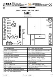
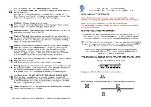
3 45ON6ON7ON8ON9ON10ONWith DIP switches 3 & 4 OFF – Safety Edge logic is selected.With the ‘normally closed’ (N.C.) contacts of a Safety Edge device wired intothe Auxiliary Input:-If the gate hits an obstruction triggering the safety device, the gate will: –Stop – Reverse away (from the obstruction) for approximately 1 second – Stopand remain in this position until another ‘Start Command’ given.Pre-Flash – Warning of impending movement.When selected, a Warning Indicator lamp or Flashing Light will start flashingapproximately 3 seconds before the gate starts to move.Automatic Closing - When selected the gate will automatically close after theopen pause time set on Trimmer Dial RV3Photocell Auto-test - When selected, a photocell test is carried out prior tomovement. For this function to work, the photocell transmitter(s) must be wiredinto terminal 5 (24v+) and a Negative (-). If a failure is detected the FlashingLamp & Warning Light will slowly flash.Encoder - The encoder unit is mounted on top of the motor and is designed todetect any changes in the rotational speed of the motor. If the gate hits anobstruction when travelling in either direction, the clutch will slip and theencoder will signal the Gate 1 causing it to:- Stop and reverse the gatesdirection (for approx. 1-2 secs.) – Stop and wait for another ‘start command’.N.B. Put the DIP switch in the off position if an encoder is not fitted.Soft Start – When selected the motor will start at a lower torque level to reduceinitial mechanical stresses.N.B. Do not use this function on very heavy or tight running gates.Braking (slowdown) – When selected, the motor/gate speed is reduced prior tothe gate reaching a limit switch. The slowdown speed is fixed but the length ofthe slowdown period can be adjusted by Trimmer Dial Rv2.N.B. Braking may not work consistently on very large and/or heavy gates.<strong>SEA</strong> - <strong>GATE</strong> 1 - <strong>CONTROL</strong> <strong>BOARD</strong>PROGRAMMING AND LOGIC GUIDE FOR A SLIDING <strong>GATE</strong>IMPORTANT SAFETY INFORMATION:Always Switch-off the mains electrical supply to the operator/Gate 1 beforeWorking-on or making any adjustments to the operator, limits, drive rack or gate.Mechanical stops are required in both open and closed positionsThe gate must be physically prevented from passing out of the upper and lowergate supports at any time.PREPARE THE <strong>GATE</strong> FOR PROGRAMMINGPosition the open and close Gate Limit Plates on to the drive racking. The LimitPlates should be positioned so as to trigger the Limit Switch and stop the gatesmovement a minimum of 25mm from the open and close physical gate stops.TIP: Limit Plate positioning can be checked by slowly and carefully manually slidingthe gate to the open and closed position and observing when relevant Limit LEDgoes out (Limit LEDs are lit when a Limit Plate is not present).Before starting the programming phase check all your wiring connections.Check that all ‘Normally Closed - N.C.’ inputs are either wire-linked out orconnected to a device i.e. Photocells.PROGRAMMING A SLIDING <strong>GATE</strong> OPERATOR WITH TRAVEL LIMITSSet logic DIP switches as shown belowONSee pages 3 & 4 for other DIP switch settings and explanations112ON11Leaf Lock Boost – DO NOT USE THIS FUNCION ON A SLIDING <strong>GATE</strong>.When the Gate 1 is used to control a hydraulic swing gate operator with‘braking (slowdown)’ selected, the final 1 second of motor run time is increasedto maximum speed to build up the operators hydraulic locking pressure whenthe gate is up-against the ground stop.Place the gate in a mid-way position and reconnect the emergency release.12ONClosing Direction – This function selects the gate closing direction without theneed to invert the motor and limit wiring.___________________________________________________________<strong>SEA</strong> (<strong>UK</strong>) Ltd – Solihull – Tel: 0121 706 9629 – Fax: 0121 764 5603 – email: sales@seaukltd.co.uk
Switch-on the mains supply to the operator/Gate 1 and check you have 4 Led litCN1CN2 - Terminal BlockIf you do not have thecorrect number of LEDlit – Switch-off themains electrical supplyto the operator/Gate 1and check all ‘normallyclosed’ N.C. inputs.Trimmer Rv1 – Motor torque (power)Operating Logic1 2ON1 2ONDIP SWITCH SETTINGSManual LogicA ‘Start Command’ opens the gate. A second ‘Start Command’ input givenwhilst the gate is opening stops the gate. A ‘Start Command’ given when thegate is closing, stops the gate.Safety LogicA ‘Start Command’ opens the gate. A second ‘Start Command’ given whilst thegate is opening stops and re-closes the gate.A ‘Start Command’ given when the gate is closing, stops and re-opens thegate.LED 1Rv1Rv2LED 11Rv3LED 10Trimmer Rv2 – Slowdown (length of time)Trimmer Rv3 – Open pause time adjustmentP2 – Radio transmitter learn buttonP1 – Time programming button1 2ON1 2ONAutomatic Logic 1A ‘Start Command’ opens the gate. A second ‘Start Command’ given when thegate is opening is ignored. A ‘Start Command’ given during the open pausetime, resets the pause time. A ‘Start Command’ given when the gate is closing,stops and re-opens the gate.Automatic Logic 2A ‘Start Command’ opens the gate. A second ‘Start Command’ given when thegate is opening is ignored. A ‘Start Command’ given during ‘open pause’ timecloses the gate immediately. A ‘Start Command’ given when the gate is closing,stops and re-opens the gate.CN3 – Terminal BlockAuxiliary Input – CN3 Terminal 11DIP switches 3 & 4 select the logic and type of Auxiliary Input required to be wired in toTerminal 11 – CN3. Please note the first two options shown below require a ‘normallyopen’ (N.O.) inputs and the last two options require ‘normally closed’ (N.C.) inputs.When pressing Button P1 and entering the programming phase for the first time, thegate’s first movement should be towards close - If the gate starts to open:- Turn-off thepower, switch Dip 12 over and start programming again from the beginning.Press Button P1 for approximately 10 seconds – LED 10 will light after 5 seconds andthe gate will start to close after 10 seconds - Release P1 when the gate starts closingThe gate will start an automatic searching process to find both the Open and ClosedLimit Switch positions by:- Closing up to and stopping at the ‘Close Limit Switch’ position.- Pausing- Automatically opening up to and stopping at the ‘Open Limit Switch’ position– Pausing– Automatically closing up to and stopping at the Close Limit Switch position.If the programming phase is successful, the programming LED will extinguish.3 43 43 4With DIP switches 3 & 4 ON - ‘Pedestrian’ logic is selected:A ‘normally open’ (N.O.) Auxiliary Input from for example a pushbutton willprovide a partial Pedestrian opening cycle.With DIP switch 3 ON & 4 OFF - ‘Timer Control’ logic is selected.With the ‘normally open’ (N.O.) – ‘volt free’ contacts of a Time Clock wired into the Auxiliary Input and ‘automatic closing’ logic selected, the Time Clock willopen and keep the gate open for the time set on the clock.With DIP switch 3 OFF & 4 ON- ‘Auxiliary Photocell’ logic is selected.When the ‘normally closed’ (N.C.) contacts of a set of photocells are wired into the Auxiliary Input – If the photocell beam is broken when the gate is:-Opening:- The gate will stop and remain in this position until the beam isrestored, when restored the gate continues opening.Closing:- The gate will stop and remain in this position until the beam isrestored, when restored the gate will re-open.Continued overleaf