Manuale GATE 2 DG Rev.02 ITA (testo nero) - SEA (UK)
Manuale GATE 2 DG Rev.02 ITA (testo nero) - SEA (UK)
Manuale GATE 2 DG Rev.02 ITA (testo nero) - SEA (UK)
- No tags were found...

Create successful ePaper yourself
Turn your PDF publications into a flip-book with our unique Google optimized e-Paper software.
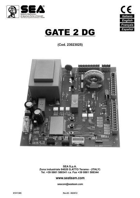
®Sistemi Elettronicidi Apertura Porte e CancelliInternational registered trademark n. 804888<strong>GATE</strong> 2 <strong>DG</strong>ItalianoEnglishFrançaisEspañol(Cod. 23023025)<strong>SEA</strong> S.p.A.Zona industriale 64020 S.ATTO Teramo - (<strong>ITA</strong>LY)Tel. +39 0861 588341 r.a. Fax +39 0861 588344www.seateam.comseacom@seateam.com67411385<strong>Rev.02</strong> - 09/2012
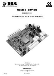
+24VdcEnc1E nc 2Fineco r sa apertur a M2/m t t h 2®Sistemi Elettronicidi Apertura Porte e CancelliInternational registered trademark n. 804888CONNESSIONI / CONNECTIONS / CONNEXIONSCONEXIONES / VERBINDUNGENATTENZIONE: la scheda è predisposta con il riconoscimento automatico degli ingressi N.C. non utilizzati(fotocellule, Stop e finecorsa) ad eccezione degli ingressi COSTA DI SICUREZZA.WARNING: The control unit is designed with the automatic detection of not used N.C. inputs (photocells,Stop and Limit switch) except the SAFETY E<strong>DG</strong>E inputs.AVERTISSEMENT: L'armoire est conçue avec la détection automatique des accès N.C. pas utilisés(photocellules, Stop et fins de course), à l'exception des accès BARRE PALPEUSE DE SECURITE.ATENCIÓN: la tarjeta está predispuesta con el reconocimiento automático de las entradas N.C. noutilizados, fotocélulas, stop y fin de carrera, con excepción de las entradas COSTA DE SEGURIDAD.ACHTUNG: Die Steuerung ist mit der automatischen Erkennung der nicht verwendeten N.C. Eingänge,ausgestattet (Lichtschranken, Stop-und Endschalter) ausgenommen des Sicherheitsleisten Eingangs.CN1<strong>GATE</strong> 2 <strong>DG</strong>RADIO MODULE (CNA)1 2 3 4 5 6 7 8 9 10 11 12 13Connettore modulo riceventeReceiver module connectorConnecteur module récepteurConector modulo receptorVerbindungsmodul EmpfängerJOLLYAntenna / AntennaAntenne / AntenaAntenneComune / CommonComun / ComúnGemeinsamStartSTART Ped./ START Ped.START Piéton / START Peat.START Fuss.StopComune / CommonComun / ComúnGemeinsamCN2Fotocellula 1/ Photocell 1Photocellule 1 / Fotocélula 1Lichtschranke 1Fotocellula 2/ Photocell 2Photocellule 2 / Fotocélula 2Lichtschranke 2Costa1 / Edge 1/ Tranche1 /Banda de seguridad1 /Sicherheitsleiste1Costa2 / Edge2 / Tranche2 /Banda de seguridad2 /Sicherheitsleiste2Comune / CommonComun / ComúnGemeinsam24VA(500 mA max)Lamp.(500mA max) /Flash (500 mA max) /Lampe (500 mA max) /Lámpara (500 mA max) /Blinklampe (500mA max)CN5Connettore Programmatore JollyConnector Programmer JollyConnecteur Programmateur JollyConector Programador JollyAnschluss Programmierer JollyCN61 2 3 4 5 6 7 8 9 10Fin e corsa apertu r a M 1 /Li m it Switch o pening M 1Finecorsa chiusura M1/L imit S w itch c losing M1CN7Li i Swi c opening M1 2 3 4F inec o rs a c hi us ur a M 2 /Li mit Sw itch c lo s in g M2-Comune / CommonComun / ComúnGemeinsam24V~(500 mA max)24VPh(500 mA max)EXPConnettore Modulo Esterno /Connector External Module /Connecteur Module Extérieur /Conector modulo externoElettroserratura /Electrolock /Electro-serrure /Electrocerradura /Elektroschloss(12V 15VA maxNota: Il carico massimo di 500 mA si riferisce alla somma dei carichi sulle uscite24V~, 24Va e Flash.Note: The maximum load of 500 mA refers to the sum of the loads on the 24V ~,24Va and Flash oputputs.Remarque: La charge maximale de 500 mA correspond à la somme des chargessur les sorties 24V ~, 24VA et Flash.Nota: La carga máxima de 500 MA se refiere a la suma de las cargas sobre lassalidas 24V ~, 24Va y Flash.Hinweis: Die maximale Belastung von 500 mA bezieht sich auf dieSumme der Lasten auf den 24V ~, 24VA und Flash Ausgängen.2 67411385<strong>Rev.02</strong> - 09/2012Lamp. Light/Flash Light /Lampe Light /Lámpara Light /Blinklampe Light1 2Lamp.N / Flash N /Lampe N /Lámpara N/Blinklampe NLinea/Line/LigneLinea/Linie1 2 3Non Connesso/Not connected/Pas connecté/No conectado/Nicht angeschlossen /Nuetro / Neutral /Neutre / Neutral /NeutralUscita Luce di cortesia temporizzabile Max 50W /Timed courtesy light output Max 50WSortie lumière de courtoisie temporisée Max 50W / Salida Luz de cortesía temporizable Max 50WAusgang zeiteinstellbare Aussenbeleuchtung Max 50WMotore 1 chiusura /Motor 1 closingCN31 2 3 4 5Motore 1 Neutro /Motor 1 NeutralM1Motore1 apertura /Motor 1 openingCondensatore Motore 1 /Capacitor Motor 1Motore 2 chiusura /Motor 2 closingCN41 2 3 4 5Motore 2 Neutro /Motor 2 NeutralM2Motore 2 apertura /Motor 2 openingCondensatore Motore 2 /Capacitor Motor 2
®Sistemi Elettronicidi Apertura Porte e CancelliInternational registered trademark n. 804888ItalianoINDICE<strong>GATE</strong> 2 <strong>DG</strong>DESCRIZIONE DEI COMPONENTI .............................................................................................4INFORMAZIONI GENERALI.........................................................................................................5AVVIO RAPIDO.............................................................................................................................6AUTOAPPRENDIMENTO TEMPI DI LAVORO.............................................................................7SELEZIONE DELLE IMPOSTAZIONI ...........................................................................................8APPRENDIMENTO RADIOCOMANDO CON RICEVENTE A BORDO SCHEDA ......................14CANCELLAZIONE TRASMETTITORI ........................................................................................14LOGICHE DI FUNZIONAMENTO ...............................................................................................15GESTIONE INSERIMENTO PASSWORD ..................................................................................15REGOLAZIONE PARAMETRI DA DISPLAY...............................................................................16CONNESSIONI START, STOP, START PEDONALE, ANTENNA E FOTOCELLULA.................18CONNESSIONI SAFETY <strong>GATE</strong> O GESTIONE AMPEROMETRICA, COSTA,LAMPEGGIATORE, LUCE DI CORTESIA..................................................................................19CONNESSIONI ALIMENTAZIONE E MOTORI...........................................................................20CONNESSIONI FINECORSA, ELETTROSERRATURA.............................................................21DESCRIZIONI ALLARMI.............................................................................................................21RISOLUZIONE DEI PROBLEMI .................................................................................................22AVVERTENZE, MANUTENZIONE E GARANZIA .......................................................................2267411385 <strong>Rev.02</strong> - 09/20123
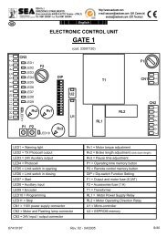
Sistemi Elettronicidi Apertura Porte e Cancelli®ItalianoInternational registered trademark n. 804888DESCRIZIONE DEI COMPONENTI<strong>GATE</strong> 2 <strong>DG</strong>F1R4R2CNPTR1F2CN7DSEXPUP DOWN OKR1CN6JOLLYT1T2CN5CNAF3CN4R3CN3CN1CN1 = Connettore ingressi/usciteCN2 = Connettore limit switch, 24V~, ElettroserraturaCN3 = Connettore motori e condensatori M1CN4 = Connettore motori e condensatori M2CN5 = Connettore uscita luce di cortesiaCN6 = Connettore alimentazioneCN7 = Connettore EncoderCNA = Connettore riceventeCNP = Connettore di programmazioneEXP = Connettore modulo espansioneJOLLY = Connettore JollyDS = Display programmazioneCN2OK = Tasto di programmazioneDOWN = Tasto di programmazioneUP = Tasto di programmazioneT1 = Triac pilotaggio motoriT2 = Triac pilotaggio motoriR1 = Relay comando motoriR2 = Relay comando luce di cortesiaR3 = Relay autotest fotocellulaR4 = Relay elettroserraturaF1 = 1A Fusibile accessoriF2 = Fusibile 6.3AT su 230V/10AT su 115VF3 = 6.3A Fusibile elettroserraturaTR1 = Trasformatore alimentazione4 67411385<strong>Rev.02</strong> - 09/2012
Sistemi Elettronicidi Apertura Porte e Cancelli®ItalianoInternational registered trademark n. 804888INFORMAZIONI GENERALI<strong>GATE</strong> 2 <strong>DG</strong>Le informazioni contenute in questa sezione del manuale sono solo per l’installatore o perpersonale qualificato o autorizzato.CARATTERISTICHE GENERALILa centrale di comando <strong>GATE</strong> 2 <strong>DG</strong> è stata progettata per comandare uno o due motori a 230V/115V 50/60Hz con o senza finecorsa elettronici.La grande novità è il DISPLAY LCD a bordo che permette di visualizzare e impostare in modo semplice ecompleto tutte le funzioni della centrale.CARATTERISTICHE TECNICHETensione di alimentazione della centraleAssorbimento in stand byCarico max. motoreCarico max. Accessori 24V (24VA)Carico max. LampeggiatoreTemperatura ambienteProtezione accessori / alimentazione /elettroserraturaLogiche di funzionamentoTempo di apertura / chiusuraTempo di pausaForza di spintaSpazio di rallentamentoIngressi in morsettieraUscite in morsettieraDimensioni schedaCaratteristiche contenitore per esternoAccessori specifici:- Scheda semaforo su connettore Aux- Programmatore su connettore Jolly- OPEN su connettore Prog peraggiornamento software230 Vac 50/60 Hz - 115Vac 50/60 Hz30 mA800 W per motore24V 500mA24V(FL) 15W max.Si consiglia l’uso del 24V Flash (Led)-20°C +50°CF1 (1 AT) / F2 (6.3 AT) / F3 (6.3 AT)Automat. / P. P.1 / P. P.2 / Sic. / U. Pres / 2 Puls.In autoapprendimento in fase di programmazioneRegolabile (da D sb a 4 min)Regolabile apertura e chiusura per singola antaRegolabili apertura e chiusura per singola antaApertura totale / Apertura pedonale regolabile /Costa bilanciata apertura e chiusura /Stop / Finecorsa apertura e chiusura /Fotocellula 1 e Fotocellula 2 / Encoder(FLS) Flash 24V / LAMP (Max 50W) /24V~ / Motori / 24VA (Max 500 mA)168 X 174 X 65 mm325,7 X 246 X 140Scheda relay per gestione per semaforo(SEM Cod. 23021100),Programmatore JOLLY (cod.23105276),Programmatore OPEN (cod.23105290)Le funzioni descritte su questo manuale sono disponibili dalla Revisione 15.67411385 <strong>Rev.02</strong> - 09/20125
®Sistemi Elettronicidi Apertura Porte e CancelliInternational registered trademark n. 804888ItalianoAVVIO RAPIDO<strong>GATE</strong> 2 <strong>DG</strong>UPDOWNOKPULSANTI DI PROGRAMMAZIONE1MENU <strong>SEA</strong> SETTrsUPUOKSaltare questa fase se non si vuole programmare un TXMENU <strong>SEA</strong> SETstrtOKMENU <strong>SEA</strong> SETpushPremere ilpulsanteTX damemorizzareMENU <strong>SEA</strong> SETUeUOK per usciredal Menuoppure premereil pulsantedel successivoTX damemorizzare2MENU <strong>SEA</strong> SETotUUPOKScegliere il tipo dimotore conUP o DOWNOKPer confermaree tornareal Menu principale3MENU <strong>SEA</strong> SETOnoUUPOKSaltare questa fase se si lavora in modalità doppia antaScegliere con UP o DOWNla voce ON solo se si èin modalità singola antaOKPer confermare e tornareal Menu principale4MENU <strong>SEA</strong> SETlogcUPOKScegliere conUP o DOWNla logica desiderataOKPer confermaree tornareal Menu principale5MENU <strong>SEA</strong> SETt.pauUPOKScegliere conUP o DOWNun tempoper la richiusuraautomaticaOKPer confermaree tornareal Menu principaleSaltare queste fasise si vuole lavorarein logicasemiautomatica6MENU <strong>SEA</strong> SETst.ps.UPOKScegliere conUP o DOWNla voce ONOKPer confermaree tornareal Menu principale78MENU <strong>SEA</strong> SETPrgUPUMENU <strong>SEA</strong> SETst.pr.OKOKScegliere con UP o DOWNla voce ON per avviarel’autoapprendimento dei tempiSaltare questa fase se è stato già memorizzato un TXScegliere con UP o DOWNla voce ON per dareuno start di provaOKOKFinito l’autoapprendimentola centrale tornerà automaticamenteal Menu principalePer confermare e tornareal Menu principaleTUTTI GLI ALTRI PARAMETRI HANNO IMPOSTAZIONI DI DEFAULT UTILI NEL 90% DELLE APPLICAZIONI MAPOSSONO ESSERE COMUNQUE REGOLATE ATTRAVERSO IL MENU SPECIALE.PER ENTRARE NEL MENU SPECIALE PREMERE CONTEMPORANEAMENTE UP E DOWN PER 5 S6 67411385<strong>Rev.02</strong> - 09/2012DOWNUP
Sistemi Elettronicidi Apertura Porte e Cancelli®ItalianoInternational registered trademark n. 804888AUTOAPPRENDIMENTO TEMPI DI LAVOROLa scheda è preimpostata con le impostazioni di default, per avviare la centrale con leimpostazioni di DEFAULT basta tenere premuti i tasti UP e DOWN contemporaneamentedando alimentazione alla scheda, fino a che non compare la scritta init sul display.Le impostazioni di DEFAULT sono indicate nella tabella dei Menu.AUTOAPPRENDIMENTO TEMPI DI LAVORO AD IMPULSI<strong>GATE</strong> 2 <strong>DG</strong>ATTENZIONE: Tale procedura è potenzialmente pericolosa e deve essere eseguita solo da personalespecializzato ed in condizioni di sicurezza.NOTA: La scheda è preimpostata con dei tempi di lavoro standard, per cui l’automazione può essere avviataanche senza effettuare la programmazione dei tempi, semplicemente regolando i tempi dal display (veditempi di default).1) Disattivare la corrente elettrica, sbloccare i motori e posizionare manualmente le ante a metà corsa.Ripristinare il blocco meccanico.2) Alimentare la scheda.3) Selezionare attraverso il display a bordo o tramite programmatore JOLLY il tipo di motore che si sta utilizzando,come indicato nella gestione display (MECC-IDRO).4) Se necessario impostare anche la logica di funzionamento e gli altri parametri. Se si vuole effettuare laprogrammazione con il TX, memorizzare un TX prima di fare la programmazione.5) Selezionare la voce PROG sul display, premere OK e poi uno dei pulsanti UP o DOWN.(Se il motore dovesse partire in apertura, togliere e rimettere l’alimentazione, selezionare sul display la voce iN. T etramite i pulsanti UP e DOWN posizionarla in ON, oppure se si dispone del programmatore Jolly, attivare la funzionescambio motore.)6) A questo punto il cancello avvierà il seguente ciclo: CHIUSURA M2 - CHIUSURA M1 - APERTURA M1 -APERTURA M2 - CHIUSURA M2 - CHIUSURA M1. Durante il ciclo, per memorizzare le rispettive battute, dare unimpulso di UP o DOWN o START ad ogni punto di battuta dell’anta.7) Autoapprendimento terminato.UAUTOAPPRENDIMENTO TEMPI DI LAVORO CON ENCODERSe è presente l’Encoder bisogna selezionare ON nel Menu ENC, a questo punto è necessario solo avviare laprogrammazione e verificare che l’anta 2 parta per prima in chiusura. Automaticamente il cancello eseguirà ilseguente ciclo: CHIUSURA M2 - CHIUSURA M1 - APERTURA M1 - APERTURA M2 - CHIUSURA M2 - CHIUSURAM1.Nota: per regolare la sensibilità di rilevamento delle battute fare riferimento al menu speciale.AUTOAPPRENDIMENTO TEMPI DI LAVORO CON SENSORE AMPEROMETRICOÈ possibile effettuare l’apprendimento dei tempi solo su cancelli elettromeccanici, sfruttando il rilevamentoautomatico delle battute.Una volta avviata la programmazione bisognerà solo accertarsi che il cancello esegua il seguente ciclo: CHIUSURAM2 - CHIUSURA M1 - APERTURA M1 - APERTURA M2 - CHIUSURA M2 - CHIUSURA M1.Nota: per regolare la sensibilità di rilevamento delle battute fare riferimento al menu speciale.APPRENDIMENTO CON FINECORSASe sono presenti i finecorsa, il cancello eseguirà automaticamente il seguente ciclo: CHIUSURA M2 - CHIUSURA M1- APERTURA M1 - APERTURA M2 - CHIUSURA M2 - CHIUSURA M1.Prima di avviare l’apprendimento, verificare, attraverso il menu di test, che vengano impegnati, per ogni anta e perogni verso di apertura, i rispettivi finecorsa.Es: per la chiusura del motore M2 deve impegnarsi il finecorsa chiusura M2.67411385 <strong>Rev.02</strong> - 09/20127
Sistemi Elettronicidi Apertura Porte e Cancelli®ItalianoInternational registered trademark n. 804888SELEZIONE DELLE IMPOSTAZIONILe impostazioni della scheda si effettuano attraverso i tasti UP, DOWN e OK. Con UP e DOWN si scorrono i MENU’ e i SOTTOMENU’, con OK si accede dal MENU’ al SOTTO MENU’ e si confermano le scelte.Tenendo premuti contemporaneamente i tasti UP e DOWN si accede al MENU’ SP, per le impostazioni speciali.Tenendo premuto il tasto OK per 5 secondi, si accede al MENU’ di test, nel quale è possibile verificare lo stato di funzionamentodi tutti gli ingressi.Sistema inizialeVISUALIZZAZIONE STATO DEGLI INGRESSIStartFinec.aperturamotore 1Finec.chiusuramotore 1Fotocellula 1StartpedonaleMENU <strong>SEA</strong> SET-----------Fotocellula 2StopCosta 1 Costa 2Finec. aperturamotore 2Finec. chiusuramotore 2Il segmento accesoindica che, in fase diautoapprendimento,lo stato dell’ingresso èchiuso o disabilitato.DOWNu.001UPVersione softwareEsempio di programmazioneUotOKUPUP<strong>GATE</strong> 2 <strong>DG</strong>UPSl dTRAIbarrDOWNOKDOWNOKDOWNOKMENUstrtstoppedoedgOEdgcPko.1Pko.2F o.iF .1DescrizioneProva StartProva StopProva Start pedonaleTabella funzioni MENU TEST INGRESSI <strong>GATE</strong> 2 <strong>DG</strong>(Si accede al Menu TEST ingressi tenendo premuto OK per 5 secondi)Prova Costa di sicurezzaProva Costa di sicurezzaProva Fotocellula 1Prova Fotocellula 2Prova finecorsa apertura M1Prova finecorsa Chiusura M1DescrizioneIl contatto deve essere N.O. Se azionando il relativo comando sul displaysi accenderà la voce SET, l'ingresso risulterà funzionante.Se la voce SET è sempre attiva controllare i cablaggi.Il contatto deve essere N.C. Se azionando il relativo comando sul displaysi accenderà la voce SET, l'ingresso risulterà funzionante. Se la voce SET èsempre accesa verificare che il contatto sia N.C..Il contatto deve essere N.O. Se azionando il relativo comando sul displaysi accenderà la voce SET, l'ingresso risulterà funzionante. Se la voce SET èsempre attiva controllare i cablaggi.Il contatto deve essere N.C. Se azionando il relativo comando sul displaysi accenderà la voce SET, l'ingresso risulterà funzionante. Se la voce SET èsempre attiva verificare che il contatto sia N.C..Il contatto deve essere N.C. Se azionando il relativo comando sul displaysi accenderà la voce SET, l'ingresso risulterà funzionante. Se la voce SET èsempre attiva verificare che il contatto sia N.C..Il contatto deve essere N.C. Se azionando il relativo comando sul displaysi accenderà la voce SET, l'ingresso risulterà funzionante. Se la voce SET èsempre attiva verificare che il contatto sia N.C..Il contatto deve essere N.C. Se azionando il relativo comando sul displaysi accenderà la voce SET, l'ingresso risulterà funzionante. Se la voce SET èsempre attiva verificare che il contatto sia N.C..Il contatto deve essere N.C. Se azionando il relativo comando sul displaysi accenderà la voce SET, l'ingresso risulterà funzionante. Se la voce SET è sempreattiva verificare che il contatto sia N.C. o che non sia impegnato il relativo finecorsa.Il contatto deve essere N.C. Se azionando il relativo comando sul displaysi accenderà la voce SET, l'ingresso risulterà funzionante. Se la voce SET è sempreattiva verificare che il contatto sia N.C. o che non sia impegnato il relativo finecorsa.F o.2F .2Prova finecorsa apertura M2Prova finecorsa chiusura M2Il contatto deve essere N.C. Se azionando il relativo comando sul displaysi accenderà la voce SET, l'ingresso risulterà funzionante. Se la voce SET è sempreattiva verificare che il contatto sia N.C. o che non sia impegnato il relativo finecorsa.Il contatto deve essere N.C. Se azionando il relativo comando sul displaysi accenderà la voce SET, l'ingresso risulterà funzionante. Se la voce SET è sempreattiva verificare che il contatto sia N.C. o che non sia impegnato il relativo finecorsa.8 67411385<strong>Rev.02</strong> - 09/2012
Sistemi Elettronicidi Apertura Porte e Cancelli®ItalianoInternational registered trademark n. 804888SELEZIONE DELLE IMPOSTAZIONI<strong>GATE</strong> 2 <strong>DG</strong>MENU Descrizione SET Descrizione Default Valore impostatoTrsUUotUonoLogT.paPrgUSt.prEndNSt.PsTrasmettitoriTipo di MotoreImpostazione singola antaLogiche di funzionamentoTempo di PausaStart in pausaAutoapprendimento tempiStart di provaUscita dal menùTABELLA FUNZIONI MENU <strong>GATE</strong> 2 <strong>DG</strong>strtstpdU.EstStopSbldel.Del.sOn Offa toNp.p.1p.p.22p lNs uNdroUO.prD sb1,2,3offoneccslidsl.ruOff onStartStart PedonaleUscita ExpStopSblocco elettrofrenoCancellazione TXCancellazione singolo TXMotori idrauliciMotori elettromeccaniciScorrevoleScorrevole reversibileIn ON attiva la modalità in singola antaAutomaticaPasso Passo tipo1Passo Passo tipo2Due pulsantiSicurezzaUomo presenteDisabilitata (logiche semiautomatiche)Regolabile da 1s a 4min.In pausa non accetta lo startIn pausa accetta lo startAvvio apprendimento tempistrtstpdOffautoD sbOff on Comando di startoffSelezionando END e Premendo OK si esce dal menu, altrimenti il menù sidisattiva automaticamente dopo 2 minutiUecc67411385<strong>Rev.02</strong> - 09/20129
Sistemi Elettronicidi Apertura Porte e Cancelli®ItalianoInternational registered trademark n. 804888SELEZIONE DELLE IMPOSTAZIONI<strong>GATE</strong> 2 <strong>DG</strong>DOWNUPTABELLA FUNZIONI MENU SPECIALE <strong>GATE</strong> 2 <strong>DG</strong>(Si accede al Menu Speciale tenendo premuti UP e DOWN contemporaneamente per 5 secondi.Si esce dal Menu Speciale premendo END o tenendo premuti UP e DOWN contemporaneamente per 5 secondi)MENU SP Descrizione SET Descrizione Default Valore impostatotr.opRegolazione ritardo antain aperturaD sb 6 Regol. Da disabilitato a 6 secondi 1,5tr.cl.Op1L1.Op2L2Pu OuR.strSd.o1Sd.c1Sd.o2Sd.c2Lg.bu.Regolazione ritardo antain chiusuraCoppia in apertura M1Coppia in chiusura M1Coppia in apertura M2Coppia in chiusura M2D sb 200 1000 1000 1000 100Regol. Da disabilitato a 20 secondiCoppia apertura M1Nota: con motori idraulici lacoppia sarà al 100%Coppia in chiusura M1Nota: con motori idraulici lacoppia sarà al 100%Coppia apertura M2Nota: con motori idraulici lacoppia sarà al 100%Coppia chiusura M2Nota: con motori idraulici lacoppia sarà al 100%DisabilitatoN. T Inversione Motori e finecorsa off Motori sincronizzato dxoffUPushOverReverse StrokeRallentamento in apertura M1Rallentamento in chiusura M1Rallentamento in apertura M2Rallentamento in chiusura M2DisbOp.clO.opeO.cloD sb 3D sb 50D sb 50D sb 50D sb 50BeeponApertura e ChiusuraSolo aperturaSolo Chiusurapr.bl. Prelampeggio D sb DisabilitatoDa disabilitato a 3 secondiDa disabilitato a 50% della corsaDa disabilitato a 50% della corsaDa disabilitato a 50% della corsaDa disabilitato a 50% della corsa1,2,3 Regolabile da 1s a 5sUscita Lampeggiante o Buzzer alys Lampeggiante sempre accesoLa pUspyLampeggiante classicoLampada spiaBuzzerMotori sincronizzato sxEnc Attivazione Encoder On Off In On abilita la lettura dell’Encoder Off2,575757575D sbD sb20202020D sbLa pT .o1 Tempo apertura motore 1 0 240 Regolazione tempo di lavoro appreso 28.6T .c1 Tempo chiusura motore 1 0 240 Regolazione tempo di lavoro appreso 28.6T .o2 Tempo apertura motore 2 0 240 Regolazione tempo di lavoro appreso 28.6T .c2 Tempo chiusura motore 2 0 240 Regolazione tempo di lavoro appreso 28.6L. O Luce di cortesia Y L Solo durante il ciclo201,2,3Luce di cortesia impostabile da 1sa 4min.Ped.o Apertura pedonale 20 100 Regola lo spazio di apertura pedonale 100P.ped Pausa PedonalestrtLa pausa in apertura pedonale èuguale a quella di apertura totale strtUUUUNPREMERE CONTEMPORANEAMENTE PER 5 S PER ACCEDERE E USCIRE DAL MENU SPECIALED sb1,2,3DisabilitataRegolabile da 1s a 4 min.U1067411385<strong>Rev.02</strong> - 09/2012
Sistemi Elettronicidi Apertura Porte e Cancelli®ItalianoInternational registered trademark n. 804888SELEZIONE DELLE IMPOSTAZIONI<strong>GATE</strong> 2 <strong>DG</strong>DOWNUPMENU SP Descrizione SET Descrizione Default Valore impostatoS.Str Soft Start 0 100 Rampa di accelerazione da 0 a 3 s. 100 %Y l Numero cicli per manutenzione 100 10e4 Regolabile da 100 a 100000 I0e4N. Yt rUNumero cicli effettuatiGestione Timeredg1 Costa di sicurezza 1Pk.iPk.224uaPREMERE CONTEMPORANEAMENTE PER 5 S PER ACCEDERE E USCIRE DAL MENU SPECIALETABELLA FUNZIONI MENU SPECIALE <strong>GATE</strong> 2 <strong>DG</strong>(Si accede al Menu Speciale tenendo premuti UP e DOWN contemporaneamente per 5 secondi.Si esce dal Menu Speciale premendo END o tenendo premuti UP e DOWN contemporaneamente per 5 secondi)Gestione fotocellula 1Gestione fotocellula 2Gestione uscita 24Vaux0 10e9D sbpk2PedOp. lO.opeO. loedg2 Costa di sicurezza 2 Op. ls.ed1s.ed2Costa di sicurezza 1Costa di sicurezza 2O.opeO. loD sb8.2D sb8.2LosOpenStopParL.iLosParL.iUrp.paopenstopUrp.paalysOp. LopenPer azzerare tenere premuto OK per 5 s.DisabilitatoFunzione Timer attiva su ingressophoto2Funzione Timer attiva su ingressopedonaleAttiva in apertura e chiusuraAttiva solo in aperturaAttiva solo in chiusuraAttiva in apertura e chiusuraAttiva solo in aperturaAttiva solo in chiusuraCoste attive ma non protetteCoste attive protette con unaresistenza da 8k2Coste attive ma non protetteCoste attive protette con unaresistenza da 8k2Fotocellula attiva in chiusuraFotocellula attiva in apertura echiusuraLa Fotocellula è attiva anche primadell'aperturaLa Fotocellula in chiusura ferma eal rilascio chiudeLa Fotocellula da un comando dichiusura immediata durante lapausa e l’aperturaLa Fotocellula ricarica il tempodi pausa sulla Foto1Fotocellula attiva in chiusuraFotocellula attiva in apertura echiusuraLa Fotocellula è attiva anche primadell'aperturaLa Fotocellula in chiusura ferma eal rilascio chiudeLa Fotocellula da un comando dichiude durante l'apertura, la pausae la chiusuraLa Fotocellula ricarica il tempodi pausa sulla Foto2Uscita 24Vaux sempre alimentataUscita 24Vaux alimentata solodurante l'apertura e la chiusuraUscita 24Vaux alimentata solodurante l'apertura67411385 <strong>Rev.02</strong> - 09/2012 11D sbOp. lOp. lD sbD sbLosOpen
DOWNUPSistemi Elettronicidi Apertura Porte e Cancelli®ItalianoInternational registered trademark n. 804888SELEZIONE DELLE IMPOSTAZIONI<strong>GATE</strong> 2 <strong>DG</strong>PREMERE CONTEMPORANEAMENTE PER 5 S PER ACCEDERE E USCIRE DAL MENU SPECIALETABELLA FUNZIONI MENU SPECIALE <strong>GATE</strong> 2 <strong>DG</strong>(Si accede al Menu Speciale tenendo premuti UP e DOWN contemporaneamente per 5 secondi.Si esce dal Menu Speciale premendo END o tenendo premuti UP e DOWN contemporaneamente per 5 secondi)MENU SP Descrizione SET Descrizione Default Valore impostatoLos Uscita 24Vaux alimentata solodurante la chiusuraPa sUscita 24Vaux alimentata solodurante la pausaef.ps Elettrofreno positivoT.serL.tiUD ag.ralph.teTl.o1Tl. 1Tl.o2Tl. 2Tempo di scattoelettroserraturaGestione luce di cortesiacon timerCoppia di iniziorallentamentoOp. LD sb 5offonDiagnostica eventi 0 100 100Sia sul finecorsa di chiusurache aperturaRegola il tempo di scatto dellaserratura da 0 a 5 sAttiva solo prima dell’aperturaPermette di tenere spenta la luce dicortesia se è attivo il timerPermette di tenere accesa la luce dicortesia se è attivo il timerVisualizza l’ultimo evento accaduto(Vedere tabella allarmi)Regola il passaggio tra coppiamassima e rallentamentoPhoto test ph1 Attiva l’autotest solo su fotocellula 1 offph2 Attiva l’autotest solo su fotocellula 2ph1.2 Attiva l’autotest su entrambeoff DisabilitatoTolleranza tra battuta e 0 100 Regola la tolleranza tra la battutaostacolo apertura motore 1e l’ostacolo0Tolleranza tra battuta e 0 100 Regola la tolleranza tra la battutaostacolo chiusura motore 1e l’ostacolo0Tolleranza tra battuta eostacolo apertura motore 2Tolleranza tra battuta eostacolo chiusura motore 2Nef.ne Elettrofreno negativoRe.Sp Recupero spazio 0 20Recupera l’inerzia del motore dopolo stop o l’inversione regolabile1da 0 a 20 sR. Ot Inversione su finecorsa D sb 3Dopo la lettura del finecorsa dichiusura il motore inverte per il tempo D sbimpostato, regolabile da 0 a 3sec.fr.enRegola la frenata sui finecorsa inRegolazione frenata su 0 100 %caso di impostazione Slide efinecorsaSlide reversibileConsente la ripetizione della funzionePo.Pr Push Over periodico D sb 8 PushOver a distanza di temporegolabile da 0 a 8h a intervalli di un’oraD sball.r Allarme antiintrusione D sbSe si libera il finecorsamanualmente forza la richiusuradel cancelloD sbO. Lo Solo su finecorsa chiusuraO.Ope Solo su finecorsa di aperturaUserrO.opeO. loOp. l0 1000 100Attiva solo prima della chiusuraAttiva prima dell’apertura e della chiusuraRegola la tolleranza tra la battutae l’ostacoloRegola la tolleranza tra la battutae l’ostacolo3O.opeoff100001267411385 <strong>Rev.02</strong> - 09/2012
DOWNUPSistemi Elettronicidi Apertura Porte e Cancelli®ItalianoInternational registered trademark n. 804888SELEZIONE DELLE IMPOSTAZIONI<strong>GATE</strong> 2 <strong>DG</strong>PREMERE CONTEMPORANEAMENTE PER 5 S PER ACCEDERE E USCIRE DAL MENU SPECIALETABELLA FUNZIONI MENU SPECIALE <strong>GATE</strong> 2 <strong>DG</strong>(Si accede al Menu Speciale tenendo premuti UP e DOWN contemporaneamente per 5 secondi.Si esce dal Menu Speciale premendo END o tenendo premuti UP e DOWN contemporaneamente per 5 secondi)MENU SP Descrizione SET Descrizione Default Valore impostatos.op1 Sensibilità su ostacolo 0 99Regola la sensibilità su Motore 1in aperturaD sbS. l1 Sensibilità su ostacolo 0 99Regola la sensibilità su Motore 1in chiusuraD sbs.op2 Sensibilità su ostacolo 0 99Regola la sensibilità su Motore 2in aperturaD sbS. l2 Sensibilità su ostacolo 0 99 Regola la sensibilità su Motore 2in chiusuraD sbS.ral Sensibilità rallentamento D sb 10Regola la sensibilità all’inversionedurante il rallentamentoD sbPermette di impostare una passwordPs.rd Inserimento password ---- che blocca la modifica dei parametridella centrale (vedi pag 15)END Uscita dal menù specialeSelezionando END e Premendo OK si esce dal menu speciale,altrimenti il menù speciale si disattiva automaticamente dopo 20 minuti67411385 <strong>Rev.02</strong> - 09/2012 13
!Sistemi Elettronicidi Apertura Porte e Cancelli®International registered trademark n. 804888Italiano<strong>GATE</strong> 2 <strong>DG</strong>AUTOAPPRENDIMENTO RADIOCOMANDOCON RICEVENTE A BORDO SCHEDAATTENZIONE: Eseguire la programmazione dei radiocomandi prima di aver collegato l’antenna e inserendo la r i c e v e n t enell’apposito connettore CMR (se disponibile) a scheda spenta. (La scheda riconoscerà automaticamente se la ricevente è unmodulo RF, RF ROLL, RF ROLL PLUS o RF UNI).Nota: Con Modulo RF Roll o RF Roll Plus sarà possibile utilizzare solo radiocomandi Coccinella Roll o Coccinella Roll Plus, oppureSmart Dual Roll o Smart Dual Roll Plus.Con modulo RF UNI sarà possibile utilizzare sia radiocomandi della serie Roll Plus che radiocomandi a codice fisso. Il primoradiocomando memorizzato determinerà la tipologia dei restanti radiocomandi.Selezionare attraverso il display la voce TrS e premere OK, a questo punto con i pulsanti UP e DOWN, selezionare il comando a cuiassociare il tasto (è possibile associare massimo 2 comandi) e premere OK per confermare la scelta, a questo punto schiacciare il pulsante delradiocomando che si vuole associare. Se la memorizzazione è andata a buon fine, sul display comparirà la scritta E .Nel caso in cui la ricevente sia Rolling Code, è necessario schiacciare 2 volte di seguito il tasto del radiocomando che si vuole programmareper memorizzare il primo TX.Nel MENU’ TrS è possibile selezionare le voci: Strt (per associare un comando di Start), StPd (Start Pedonale), .Est (Per azionare uncontatto sull’uscita EXP), StoP (Per associare al TX il comando di STOP), dEL. (Per cancellare tutti i TX), del.s (Per cancellare il singolo TXsolo se è un TX Rolling Code Plus), sbl (per associare al TX lo sblocco dell’elettrofreno). Per sbloccare l’elettrofreno è necessario dare 3impulsi consecutivi, il 4° implulso riattiverà il blocco dell’elettrofreno.Note:- Eseguire l’apprendimento di radiocomando solo a ciclo fermo e cancello chiuso.- Se i radiocomandi sono Rolling Code sarà possibile memorizzare fino a 800 codici (pulsanti).- Se i radiocomandi sono a codice fisso sarà possibile memorizzare fino ad un massimo di 30 codici (pulsanti).- E’ possibile memorizzare massimo 2 delle 4 funzioni disponibili. Se viene ricevuto un codice che era già stato assegnato ad una funzioneverrà aggiornato con la nuova funzione.UUCANCELLAZIONE DEI TX DALLA RICEVENTECon moduli diversi da RF UNI, sarà possibile cancellare solo l’intera memoria della RX.Procedere in questo modo: selezionare dal menu TrS la voce DEL e tenere premuto il pulsante OK finchè sul display non appare la scrittaDONE.UCon modulo RF UNI, sarà possibile cancellare anche il singolo tasto del TX.È possibile procedere in due modi:1) Se si possiede il TX, o si stanno utilizzando TX a codice fisso, la cancellazione può essere effettuata semplicemente per ritrasmissione delcodice. Es. Tasto 1 del TX memorizzato come START: accedere al menu TrS premere OK, selezionare la voce STRT, premere OK.Inviare il comando di STRT dal TX e dal display comparirà la scritta DEL.A questo punto il singolo tasto risulterà eliminato.UUUU2) Se non si possiede il TX, o si stanno utilizzando TX Roll Plus, si può effettuare la cancellazione del TX selezionando semplicemente ilnumero di serie del TX da eliminare.Procedere in questo modo: accedere al menu TrS , premere OK, selezionare la voce DELS, premere OK, scegliere la locazione di memoriada eliminare attraverso i pulsanti UP e DOWN, premere OK, verificare sul display che il numero seriale del TX da eliminare sia quello giusto,premere OK, comparirà sul display la scritta SURE, se il TX da cancellare è quello giusto premere OK, altrimenti premere il tasto DOWN pertornare al menu TrS .UUNota: in caso di utilizzo dei TX Roll Plus, si consiglia di riportare, su una tabella simile quella di esempio sottostante, il numero di serieassociandolo alla locazione di memoria su cui è stato memorizzato.14ESEMPIOTABELLALocazionedi memoria01234567891011121314151617181920PulsanteTX1 2 3 467411385 <strong>Rev.02</strong> - 09/2012Numero di serieCliente
®Sistemi Elettronicidi Apertura Porte e CancelliInternational registered trademark n. 804888ItalianoLOGICHE DI FUNZIONAMENTO<strong>GATE</strong> 2 <strong>DG</strong>LOGICA AUTOMATICAUn comando di start apre il cancello. Un secondo impulso durante l’apertura non viene accettato.Un comando di start durante la chiusura inverte il moto.NOTA1 :Per avere la chiusura automatica è necessario impostare un tempo di pausa, altrimenti tutte le logiche risulteranno semiautomaticheNOTA2: E’ possibile scegliere se far accettare o meno lo start in pausa, selezionando dal MENU’ la voce St.PS e scegliendo ON o OFF.Di default il parametro è in OFF.LOGICA DI SICUREZZAUn comando di start apre il cancello. Un secondo impulso durante l’apertura inverte il moto.Un comando di start durante la chiusura Inverte il moto.NOTA1: Per avere la chiusura automatica è necessario impostare un tempo di pausa, altrimenti tutte le logiche risulteranno semiautomatiche.NOTA2: E’ possibile scegliere se far accettare o meno lo start in pausa, selezionando dal MENU’ la voce St.PS e scegliendo ON o OFF.Di default il parametro è in OFF.LOGICA PASSO PASSO TIPO1Il comando di start segue la logica APRE-STOP-CHIUDE-STOP-APRE.NOTA1 :Per avere la chiusura automatica è necessario impostare un tempo di pausa, altrimenti tutte le logiche risulteranno semiautomaticheNOTA2: E’ possibile scegliere se far accettare o meno lo start in pausa, selezionando dal MENU’ la voce St.PS e scegliendo ON o OFF.Di default il parametro è in OFF.LOGICA PASSO PASSO TIPO2Il comando di start segue la logica APRE-STOP-CHIUDE-APRE.NOTA1 :Per avere la chiusura automatica è necessario impostare un tempo di pausa, altrimenti tutte le logiche risulteranno semiautomaticheNOTA2: E’ possibile scegliere se far accettare o meno lo start in pausa, selezionando dal MENU’ la voce St.PS e scegliendo ON oOFF. Di default il parametro è in OFF.LOGICA UOMO PRESENTEIl cancello si aprirà fintanto che si mantiene premuto il pulsante di apertura Start; rilasciandolo il cancello si arresta. Il cancello si chiude fintantoche si mantiene premuto il pulsante collegato allo Start pedonale; rilasciandolo il cancello si arresta. Per effettuare i cicli completi di aperturae/o chiusura occorre tenere costantemente premuti i relativi pulsanti.LOGICA 2 PULSANTIUno start apre, uno start pedonale chiude. In apertura non è accettata la chiusura. In chiusura un comando di start riapre, un comando di startpedonale (chiudi) viene ignorato.GESTIONE INSERIMENTO PASSWORDCon scheda nuova tutti i menu saranno visualizzabili e impostabili e la password risulterà disabilitata.Selezionando uno dei MENU' e tenendo premuti UP e DOWN contemporaneamente per 5 secondi, si accede al MENU' SP nel quale èpresente il sotto MENU' denominato PS.rd.Premendo OK nel menu PS.rd. si accede all'inserimento della PASSWORD di 4 cifre. Con UP e DOWN sarà possibile incrementare odecrementare la cifra; con OK sarà possibile confermare la cifra scelta passando automaticamente all'inserimento della successiva; dando OKall'ultima cifra comparirà la dicitura SURE; dando ancora OK si confermerà l'attivazione della PASSWORD e verrà visualizzato il messaggioDONE; invece premendo UP o DOWN sarà possibile annullare l'operazione e verrà visualizzata la voce NULL.La PASSWORD inserita sarà definitivamente attiva appena scaduto il timeout di spegnimento del display, oppure spegnendo e riaccendendola centrale. Una volta attiva la PASSWORD i menu diventeranno solo visualizzabili e non impostabili, per sbloccarli sarà necessario inserire laPASSWORD corretta nel menu PS.rd; se la PASSWORD inserita risultasse sbagliata verrà visualizzato il messaggio ERR.A questo punto se la password è stata inserita correttamente i menu risulteranno sbloccati e sarà di nuovo possibile modificare i parametri dellacentrale.Sbloccata la scheda, sarà possibile inserire nel menu PS.rd. una nuova e diversa PASSWORD con la stessa metodologia dell'inserimento dellaprima, a questo punto la vecchia PASSWORD non sarà più valida.Se la PASSWORD viene dimenticata, l'unico modo per sbloccare la centrale è quello di contattare l'assistenza tecnica <strong>SEA</strong>, la quale valuteràse fornire o meno la procedura di sblocco della centrale.N.B: La password non è impostabile usando il palmare Jolly.67411385 <strong>Rev.02</strong> - 09/2012 15
®Sistemi Elettronicidi Apertura Porte e CancelliInternational registered trademark n. 804888Italiano<strong>GATE</strong> 2 <strong>DG</strong>REGOLAZIONE PARAMETRI PROGRAMMATORE JOLLYIl programmatore JOLLY permette di tenere sotto controllo e modificare tutti i parametri della scheda senza accedere ai tasti abordo scheda. Rispetto al display a bordo, il programmatore permette di visualizzare le istruzioni di programmazione nella linguadell’utente e in modo non codificato. Inoltre con il programmatore JOLLY, l’utente può lavorare comodamente in piedi senzaguardare la centrale.Parametri visualizzabili solo con la revisione software 37.Schermata 1Language: ITSchermata 2MotoreEncSp.Rall.A1Sp.Rall.C1Lingue disponibili IT,EN,FR,ES [ Italiano, Inglese, Spagnolo, Francese][Mecc./Idro/Scorrevole/Scorrevole reversibile]Encoder [on/off][Off÷100 ] regola lo spazio di rallentamento del motore1 in apertura[Off÷100 ] regola lo spazio di rallentamento del motore1 in chiusuraLa freccia indicache il parametro èmodificabile con ipulsanti + e -Schermata 3Sp.Rall.A2Sp.Rall.C2SoftStartCoppia ap.M1[Off÷100 ] regola lo spazio di rallentamento del motore2 in apertura[Off÷100 ] regola lo spazio di rallentamento del motore2 in chiusura[0÷100 ] regola la rampa di accelerazione[10÷100]% (corrente massima dei motori)Schermata 4Coppia ch.M1Coppia ap.M2Coppia ch.M2Ciclo[10÷100]% (corrente massima dei motori)[10÷100]% (corrente massima dei motori)[10÷100]% (corrente massima dei motori)[Passop.1,Passop.2,Auto,Sicur,Uomo pr.,due puls.]Schermata 5Anta doppia / Mono antaTempo di pausa [0÷240]s (tempo di pausa in secondi, 0s logiche semiautomatiche)Apprendimento Apprendimento tempi [On-Off]Cicli[0÷... ] (numero di cicli eseguiti)Schermata 6Ap. Ped.Ritardo Aper.Ritardo Chiu.Intrusione[30÷100]% (percentuale di apertura pedonale)[Off÷6s]% (Ritado anta in apertura)[Off÷20s]% (Ritado anta in chiusura)[Off,Aper,Chius.,Aper.ch.] (Implica la presenza di un contatto N.C. sufinecorsa che se liberato forza i motori in chiusura )Schermata 7Prelamp. [Chius, Off, 0÷5s] (Solo prima della chiusura, spento o da 0 a 5s)T.cortesia [Ciclo, Off, 0÷240s] (Solo durante il ciclo, spenta o da 0 a 240s)Ph.testMax Cicli[½-1,2] (Solo su Foto1, solo su Foto2, su entrambi)[100÷100000] (numero di cicli per la manutenzione)Schermata 8FlashFoto1Foto2Costa 1[Normale/Spia/Sempre/beep][chius./aper./stop/park/ch.subito/ric.pausa][chius./aper./stop/park/ch.subito/ric.pausa]In 8K2 gestisce una costa bilanciata con una resistenza da 8k21667411385 <strong>Rev.02</strong> - 09/2012
®Sistemi Elettronicidi Apertura Porte e CancelliInternational registered trademark n. 804888Italiano<strong>GATE</strong> 2 <strong>DG</strong>REGOLAZIONE PARAMETRI PROGRAMMATORE JOLLYSchermata 9Costa 2Costa 1Costa 2ElettroserraturaSchermata 10TimerRecup. pos.24V aux (24VA)Start in pausaSchermata 11Inv. Mot.StartRev. Mot.P.PedIn 8K2 gestisce una costa bilanciata con una resistenza da 8k2Attiva in: apertura e chiusura, solo apertura, solo chiusuraAttiva in: Apertura e chiusura, solo apertura, solo chiusuraAttiva in: Chiusura e apertura, solo chiusura, solo apertura[OFF-Ped-Foto2] (Permette l’attivazione di un timer sull’ingressoFoto2 o sul Pedonale)[0÷100]% (percentuale di recupero della posizione)[ciclo/aper./chius./pausa/sempre/elettrofr.positivo/elettrofr.negativo][ON/OFF] (Se in ON ed è in ON la Chius. Auto. Uno startprovocherà la richiusura immediata dell’automazione)[ON/OFF] Permette di scambiare contemporaneamenteil finecorsa e il senso di rotazione del motore senzascollegare i cavi[ON/OFF] (equivale a dare uno start di prova)[0÷100%] ( Attiva un’inversione a fine chiusura)[start, Off, 0÷240 sec] (Differenzia la pausa pedonale da quella totale)Schermata 12Tl.ap.1 [0÷ 100%] (Tolleranza fra battuta e ostacolo )Tl.ch.1 [0÷ 100%] (Tolleranza fra battuta e ostacolo )Tl.ap.2 [0÷ 100%] (Tolleranza fra battuta e ostacolo )Tl.ch.2 [0÷ 100%] (Tolleranza fra battuta e ostacolo )Schermata 13Push ov.Colpo d’antaP.O.PR.Elettroserr.[Off,Aper.,chius.,Aper.ch.] (Attiva i motori a massima coppia a finechiusura a fine apertura o in entrambi i casi)[0÷3 sec] (facilita lo sgancio dell’elettroserratura)[0÷8 ore] (Attiva il Push Over periodico a motori fermi)[0 a 5s] (Attiva lo scatto della serratura da 0 a 5 secondi)Schermata 14Sense ap.m1Sense ch.m1Sense ap.m2Sense ch.m2Schermata 15Sense rall.C.rall.TM.O.1TM.C.1Schermata 16TM.O.2TM.C.2L.TimerSchermata 17Eventi67411385[off÷ 100%] (Tolleranza fra battuta e ostacolo)[off÷ 100%] (Tolleranza fra battuta e ostacolo)[off÷ 100%] (Tolleranza fra battuta e ostacolo)[off÷ 100%] (Tolleranza fra battuta e ostacolo)[Off÷ 100%] (Tolleranza fra battuta e ostacolo)[0÷ 100%] (Rampa di decelarazione)[0 ÷ ...sec] (Visualizza il tempo di apertura dell’anta1)[0 ÷ ...sec] (Visualizza il tempo di chiusura dell’anta1)[0 ÷ ...sec] (Visualizza il tempo di apertura dell’anta2)[0 ÷ ...sec] (Visualizza il tempo di chiusura dell’anta2)[Off-On] Permette di tenere accesa o spenta la luce dicortesia se attivo un TimerRiassume nell’ordine gli ultimi 10 eventi accaduti sulla centralina<strong>Rev.02</strong> - 09/201217
®Sistemi Elettronicidi Apertura Porte e CancelliInternational registered trademark n. 804888ItalianoSTART - STOP - START PEDONALE - ANTENNAFOTOCELLULACollegamento fotocellula 1 e fotocellula 2Nota: se le fotocellule non sono collegate non è necessario fare un ponticello tra i morsetti (6e 7 e/o 6 e 8 di CN1).+ = 24VA COM = 0V PH1 = Contatto Fotocellula 1 PH2 = Contatto Fotocellula 2Nota: Per effettuare l’Autotest nel menu Ph.te selezionare la fotocellula o le fotocellule sulle quali sivuole effettuare l’Autotest. L’Autotest è possibile solo alimentando il TX delle fotocellule sulla 24V~.Di default la fotocellula 1 è impostata come FOTO CLOSE e la fotocellula 2 come FOTOOPEN. La Fotocellula 2 può essere impostata anche come TIMER (vedi funzione TIMER).<strong>GATE</strong> 2 <strong>DG</strong>CN11 2 3 4 5 6 7 8 9 10 11 12 13- C+OPZIONI su FOTO1 e FOTO2 impostabili con display a bordo o conpalmare JollyAttivazione FOTO CLOSE ( Los): Se impegnata, in chiusura inverte il moto, durantela pausa impedisce la chiusura.Attivazione RIPETI PAUSA (rP.PA): Se impegnata durante la pausa ricarica il timerdella pausa. In chiusura inverte il moto.Attivazione FOTO OPEN (oPEn): Se attivo, la fotocellula blocca il moto finchèimpegnata, al rilascio continua l’apertura.STARTAttivazione FOTO PARK ( Par ): in apertura non è attiva; in pausa comanda la START PED.chiusura al rilascio altrimenti non è attiva; in chiusura ferma il movimento finchè è3impegnata, al rilascio continua la chiusura.6Attivazione FOTO STOP (SToP): Se attivo prima dell'apertura la fotocellula blocca4l'automazione finchè impegnata, durante l'apertura viene ignorata. In chiusural'intervento della fotocellula provoca la riapertura.Attivazione FOTO CHIUDI SUBITO: la fotocellula ferma il cancello finchè impegnata5sia in apertura che in chiusura e al rilascio dà un comando di chiudi (la chiusura6avverrà un secondo dopo il rilascio della fotocellula).STOPOpzioni 24VA impostabili con Display a bordo o conpalmare Jolly.È possibile scegliere quando avere tensione sull’uscita 24VA.Le opzioni sono: sempre, solo durante l’apertura, solodurante il ciclo, solo prima dell’apertura, solo in pausaoppure per la gestione dell’elettrofreno positivo onegativo.START PEDONALE (N.O.) Lo start pedonale è collegabiletra i morsetti 2 e 4 della morsettiera CN 1.Questo ingresso permette di avere un’apertura parziale, il cuispazio di apertura è impostabile attraverso il display a bordooppure attraverso il palmare JOLLY.Nota1: il contatto per l’apertura parziale è un contattonormalmente aperto (N.O.).Nota2:In logica 2 PULSANTI è necessario tenere premuto loStart ped per richiudere l’automazione.Nota3: In logica Uomo Presente questo pulsante se trattenutoeffettua la richiusura.Nota4: se questo ingresso rimane impegnato in pausa, ilcancello non richiude finchè non viene liberato.Attivazione TIMER: Questo ingresso può essere trasformato inTIMER (Vedi TIMER)CN21 2 3 4 5 6 7 8 9 10- +CCN21 2 3 4 5 6 7 8 9 10- +CRX1677 RX267686 TX1N.B: se si vuole l’Autotestcollegare i TX ai contatti 7e 8, se non si vuolel’Autotest collegare i TX aicontatti 6 e 7.87TX287STOP (N.C.) Lo STOP è collegabile tra i morsetti 2 e 5 della morsettiera CN 1.Se si preme questo pulsante il motore si ferma immediatamente in qualunque condizione/posizione. E’ necessario un comando di start perripristinare il movimento. In seguito ad uno stop il motore ripartirà sempre in chiusura.18START (N.O.) Lo START è collegabile tra i morsetti 2 e 3 della morsettiera CN1.Se si trasmette un impulso a questo ingresso si determina l’apertura/chiusura dell’automazione.Può essere trasmesso tramite un pulsantea chiave, una tastiera, ecc... Lo start trattenuto innesca la funzione TIMER, al rilascio dello start l’automazione ripeterà il tempo di pausa epoi eseguirà la richiusura. Per collegare i dispositivi forniti (ad esempio la spira) si prega di vedere le relative istruzioni.Nota1: In logica UOMO PRESENTE è necessario tenere premuto lo Start per avere l’apertura dell’automazione.Nota2: In logica 2 PULSANTI questo pulsante esegue l’apertura.TIMERPuò essere abilitato attraverso il display a bordo o tramite programmatore JOLLY . In entrambi i casi è un contatto N.O. che provocal’apertura dell’automazione mantenendola aperta finchè attivo. Al suo rilascio il cancello attenderà la pausa impostata ed effettuerà larichiusura. Il comando di TIMER è attivabile a scelta sugli ingressi FOTO2, START PEDONALE o mantenendo impegnato l’ingresso diSTART.Nota1: Se attivo sull’ingresso pedonale, il pedonale verrà disabilitato anche sul radiocomando.Nota2: In caso di intervento di una sicurezza durante il timer (Stop, Amperometrica, Costa), sarà comunque necessario uno startdell’utente per ripristinare il motoNota3: In caso di mancata alimentazione a cancello aperto con TIMER attivo il cancello ne ripristinerà l’uso, altrimenti se al ritornodell’alimentazione il TIMER è disabilitato sarà necessario uno start per ottenere la richiusura.67411385 <strong>Rev.02</strong> - 09/2012
®Sistemi Elettronicidi Apertura Porte e CancelliInternational registered trademark n. 804888Italiano<strong>GATE</strong> 2 <strong>DG</strong>SAFETY <strong>GATE</strong> O GESTIONE AMPEROMETRICADISPOSITIVO AMPEROMETRICO PER MOTORI ELETTRO-MECCANICIQuesta centrale è dotata di un sistema di rilevamento ostacolo funzionante solo per i motori elettromeccanici che permette diavere l’inversione sull’ostacolo e il rilievo automatico delle battute.La sensibilita è regolabile nel Menu speciale da disb a 99%. Più la percentuale è alta, più sarà difficile rilevare l’ostacolo. Condispositivi idraulici questo parametro risulterà sempre disabilitato.SAFETY <strong>GATE</strong>Il Safety Gate, a differenza del sensore amperometrico, può essere usato sia sumotori elettromeccanici che idraulici.Il Safety Gate è un ENCODER che permette di avere il rilevamento della posizione delcancello e l’inversione in caso di ostacolo. Per utilizzare l’ENCODER è necessarioattivare l’Encoder nell’apposito Menu ENC. La sensibilità sull’ostacolo è regolabiledallo 0 - 99%. Più la percentuale è alta più sarà difficile rilevare l’ostacolo.CN71 2 3 4+24V ENC1 ENC2 GNDATTENZIONE: la prima manovra,dopo mancata alimentazione,avverrà a velocità impostata pereffettuare la ricerca delle battutemeccaniche di finecorsa.SAFETY <strong>GATE</strong> 1SAFETY <strong>GATE</strong> 21123 434COSTA DI SICUREZZA E LAMPEGGIATORECOSTA DI SICUREZZAÈ possibile collegare due coste di sicurezza (E<strong>DG</strong>1 e E<strong>DG</strong>2) rispettivamente tra i contatti 9, 11 e 10 e 11 di CN1.E<strong>DG</strong>1 e E<strong>DG</strong>2, se schiacciati, aprono il contatto provocando un’inversione parziale del moto sia chiusura che in apertura.Nota1: i contatti N.C. se non usati devono essere ponticellati. Gli ingressi E<strong>DG</strong>1ed E<strong>DG</strong>2 sono impostabili solo in chiusura, solo in apertura oppure in entrambele direzioni.Nota2: è possibile attivare la costa bilanciata 8K2 attraverso il display a bordo otramite il programmatore JOLLY, in tal caso il contatto costa risulterà controllatoda uno specifico valore di resistenza rilevando così l’eventuale cortocircuitoinvolontario del dispositivo. In caso di sbilanciamento del dispositivo compariràuno specifico allarme sul display a bordo o sul palmare JOLLY.CN110 11 12 131 2 3 4 5 6 7 8 9- C+Lampeggiatore 24V 15W Max (Lampada spia)10 11Il lampeggiatore è collegabile tra i morsetti FLS e COM di Cn1 (SiE<strong>DG</strong>1 Costa diE<strong>DG</strong>2 Costa diconsiglia l’uso del lampeggiante Flash Led 24V)sicurezza chiusurasicurezza aperturaIl lampeggiatore avvisa che il cancello automatico è in movimentoeseguendo 1 lampeggio al secondo in apertura e 2 lampeggi al secondo inchiusura. Rimane invece acceso fisso in pausa. Attraverso il lampeggianteè anche possibile individuare delle segnalazioni di allarme legate ai dispositivi di STOP, FOTOCELLULA 1, FOTOCELLULA2e COSTA. Attraverso il display a bordo o tramite palmare JOLLY è possibile attivare la funzione prelampeggio e/o modificarela funzione del lampeggiatore scegliendo tra lampeggio fisso, lampada spia o Buzzer.Il prelampeggio è temporizzabile da 0 a 5 s. oppure è possibile averlo solo prima della chiusura.LUCE DI CORTESIACN51 291113Temporizzabile da 0 a 4 min(230V~ 50W Max - 115V~ 50W Max)1167411385<strong>Rev.02</strong> - 09/2012 19
®Sistemi Elettronicidi Apertura Porte e CancelliInternational registered trademark n. 804888ItalianoCONNESSIONE MOTORI, CAPAC<strong>ITA</strong>’E ALIMENTAZIONECN3<strong>GATE</strong> 2 <strong>DG</strong>CN41 2 3 4 5 1 2 3 4 5CN4CN3Phase 1NeutroPhase 2Phase 1NeutroPhase 2Cap M145Cap M245Motore 1Connessione motore 1M1M = Apertura/ChiusuraCom = COMUNEEsempio1CN6231Motore 2Connessione motore 2M = Apertura/ChiusuraM21 2 3LineaNeutroCom = COMUNEEsempio23INGRESSO ALIMENTAZIONENOTA: Per il collegamento dell’alimentazione seguire lenorme vigenti.132067411385<strong>Rev.02</strong> - 09/2012
®Sistemi Elettronicidi Apertura Porte e CancelliInternational registered trademark n. 804888Italiano<strong>GATE</strong> 2 <strong>DG</strong>COLLEGAMENTI FINECORSA , ELETTROSERRATURAFinecorsaSe non collegati non devono essere ponticellati.Per la funzione finecorsa è necessaria la presenza sia dei finecorsa dichiusura che di apertura. In caso di singola anta non è necessarioponticellare i finecorsa del motore 2.È possibile attivare la funzione antiintrusione. Tale funzione è legataalla presenza di almeno un finecorsa, che se liberato forza il motore inrichiusura.!Per il corretto funzionamento dei finecorsa ci deve esserecorrispondenza tra il verso di movimentazione dei motori e irispettivi finecorsa impegnati.Com = ComuneC= ContattoFinecorsaapertura M2Finecorsachiusura M2SegnalazioneFAULFT.24FT.AUFT.LIF.E<strong>DG</strong>F.PHOFT.fFT.FLY LUscita elettroserraturaPuò essere collegata un’elettroserratura di12V 15W max. È possibile disattivare l’elettroserratura se non utilizzata.Questa operazione consente un risparmio energeticodell’apparecchiatura. Lo scatto dell’ elettroserratura è temporizzabile da0 a 5 s. L’elettroseratura è impostabile solo prima dell’apertura, solo primadella chiusura oppure in entrambe le direzioni.INDICAZIONI ALLARMINota: Per uscire dalle segnalazioni di errore premere OK. Se l'errore persiste effettuare tutti controlli previsti per l'errore specifico e/ostaccare il dispositivo che genera l'errore per verificare se l'errore scompare.La sequenza di lampeggi è segnalata sul lampeggiatore ad ogni apertura e chiusura dell’automazione. Il lampeggiatore emetterà unlampeggio al secondo in apertura e due lampeggi al secondo in chiusura, mentre rimarrà acceso fisso in pausa.E' possibile visualizzare gli allarmi anche sul lampeggiante o sulla lampada spia, semplicemente osservando il numero di lampeggi emessie verificandone la corrispondenza nella tabella sottostante:Numero lampeggi92364Finecorsaapertura M1Finecorsachiusura M1N.C.N.C.Tipo di allarmeFault corrente motoriFault alimentazione 24VN.C.N.C.Fault tensione uscita 24VAFault alimentazione di reteFault ingresso costa bilanciatoFault autotest fotocelluleFault attivazione finecorsaFault lampeggianteMax cicliTipo di allarmeFault motoriFotocellula in chiusuraFotocellula in aperturaCollisione aperturaCosta di sicurezza515253541 2 3 4 5 6 7 8 9 10Numero lampeggi5764 VelociCN29 10ELETTRO-SERRATURASoluzioneVerificare che non ci siano corto circuiti sul motore o sulla apparecchiatura.Verificare che non ci siano corto circuiti sui cablaggi o sulla apparecchiatura oche non ci sia un sovraccarico.Verificare che non ci siano corto circuiti sui cablaggi o sulla apparecchiatura oche non ci sia un sovraccarico.Verificare la presenza della rete oppure il fusibile F2.Verificare la presenza di un valore resistivo da 8.2 KÙ sull'ingresso costa, se nonpresente inserirlo oppure disabilitare la lettura dell'8k2 nell'apposito menù.Verificare il funzionamento delle fotocellule e/o le connessioni sulla centrale.Verificare il funzionamento di entrambi i finecorsa e/o la corrispondenza tra versodi movimentazione del motore e finecorsa impegnato.Verificare le connessioni e/o le condizioni della lampada.Effettuare la manutenzione e/o azzerare il numero di cicli eseguiti.Tipo di allarmeStopCicli massimi raggiuntiCollisione chiusuraErrore finecorsa67411385<strong>Rev.02</strong> - 09/2012 21
Sistemi Elettronicidi Apertura Porte e CancelliAvvertenze®International registered trademark n. 804888RISOLUZIONE DEI PROBLEMIAssicurarsi che tutti le sicurezze siano attiveTutti i contatti N.C. Devono essere ponticellatiProblema Trovato Possibile Causa SoluzioniIl motore non risponde ad alcuncomando di STARTItalianoa.) Manca un ponticello su uno deiCollegamenti N.C.b.) Fusibile bruciato<strong>GATE</strong> 2 <strong>DG</strong>a.) Controllare i collegamenti o i ponticellisui collegamenti della costa disicurezza, dello stop e delle fotocelluleb.) Sostituire il fusibile bruciato sulla schedaIl cancello non si muove mentreil motore funzionaIl cancello non raggiunge laposizione completadi apertura/chiusuraIl cancello si apre ma nonsi chiudeIl cancello non si chiudeautomaticamentea.) Il motore è in posizione di sbloccob.) C’è un ostacoloa.) Erronea regolazione dei finecorsab.) Errore di programmazionec.) Il cancello è bloccato da un ostacolod.) Coppia troppo bassaa.) I contatti delle fotocellule sono apertib.) Il contatto stop è apertoc.) Il contatto costa è apertod.) Allarme amperometricoa.) Il tempo di pausa è troppo elevatob) La scheda è in logica semiautomaticaa.) Ribloccare il motoreb.) Rimuovere l’ostacoloa.) Regolare i finecorsab.) Ripetere la programmazionec.) Rimuovere l’ostacolod.) Aumentare il parametro coppiaa.) b.) c.) Controllare i ponticelli o lesegnalazioni indicate sul lampeggiatored.) Verificare se intervenuto l’allarmeamperometrico ed eventualmenteaumentare il parametro coppia.a.) Regolare il tempo di pausab) Impostare ad un valore diversoda il parametro pausaD sbMANUTENZIONEPeriodicamente, in funzione del numero di manovra e del tipo di cancello, è opportuno provvedere, qualora il cancello abbia modificato gli attritie non funziona, alla riprogrammazione dei tempi di apprendimento sull'apparecchiatura elettronica.Periodicamente mantenere pulite le ottiche delle fotocellule.RICAMBILe richieste per parti di ricambio devono pervenire presso:<strong>SEA</strong> S.p.A. - Zona Ind.le, 64020 S.ATTO - Teramo - ItaliaSICUREZZA E COMPATIBILITÀ AMBIENTALESi raccomanda di non disperdere nell'ambiente i materiali di imballaggio del prodotto e/o circuiti.CORRETTO SMALTIMENTO DEL PRODOTTO (rifiuti elettrici ed elettronici)(Applicabile in paesi dell'Unione Europea e in quelli con sistema di raccolta differenziata)Il marchio riportato sul prodotto o sulla sua documentazione indica che il prodotto non deve essere smaltito con altri rifiuti domestici al terminedel ciclo di vita. Per evitare eventuali danni all'ambiente o alla salute causati dall'inopportuno smaltimento dei rifiuti, si invita l'utente a separarequesto prodotto da altri tipi di rifiuti e di riciclarlo in maniera responsabile per favorire il riutilizzo sostenibile delle risorse materiali.Gli utenti domestici sono invitati a contattare il rivenditore presso il quale è stato acquistato il prodotto o l'ufficio locale preposto per tutte leinformazioni relative alla raccolta differenziata e al riciclaggio per questo tipo di prodotto.IMMAGAZZINAMENTOTEMPERATURE DI STOCCAGGIOT min T Max Umidità min Umidità Max- 20°C + 65°C 5% non condensante 90% non condensanteLa movimentazione del prodotto deve essere seguita con mezzi idonei.Pagina dedicata sia all’utente che all’installatoreLIMITI DI GARANZIAPer la garanzia vedere le Condizioni di vendita riportate nel Listino ufficiale Sea.La <strong>SEA</strong> si riserva il diritto di apportare le modifiche o variazioni che ritenesse opportune ai propri prodotti e/o al presente manuale senza alcunobbligo di preavviso.2267411385 <strong>Rev.02</strong> - 09/2012
®Sistemi Elettronicidi Apertura Porte e CancelliInternational registered trademark n. 804888EnglishINDEX<strong>GATE</strong> 2 <strong>DG</strong>COMPONENTS...........................................................................................................................24GENERAL INFORMATION .........................................................................................................25QUICK START ............................................................................................................................26WORKING TIMES SELFLEARNING .........................................................................................27SETTINGS ..................................................................................................................................28RADIO TRANSMITTER LEARNING WITH ON BOARD RECEIVE UNIT ..................................34TRANSMITTERS CANCELLATION ............................................................................................34WORKING LOGICS ....................................................................................................................35PASSWORD ENTERING MANAGEMENT .................................................................................35DISPLAY PARAMETERS REGULATION....................................................................................36START, STOP, PEDESTRIAN START, ANTENNA, PHOTOCELL CONNECTIONS...................38SAFETY <strong>GATE</strong> OR AMPEROMETRIC ADMINISTRATION, E<strong>DG</strong>E, WARNING LAMP,COURTESY LIGHT CONNECTIONS ........................................................................................39POWER SUPPLY AND MOTOR CONNECTION........................................................................40LIMIT SWITCH, ELECTROLOCK CONNECTIONS ...................................................................41ALARM DESCRIPTION .............................................................................................................41TROUBLE SHOOTING ..............................................................................................................42WARNING, MAINTENANCE AND WARRANTY .........................................................................4267411385<strong>Rev.02</strong> - 09/2012 23
®Sistemi Elettronicidi Apertura Porte e CancelliInternational registered trademark n. 804888EnglishCOMPONENTS<strong>GATE</strong> 2 <strong>DG</strong>F1R4R2CNPTR1F2CN7DSEXPUP DOWN OKR1CN6JOLLYT1T2CN5CNAF3CN4R3CN3CN1CN1 = Input/output connectorsCN2 = Limit switch, 24V~, Electrolock connectorCN3 = M1 Motors and capacitors connectorCN4 = M2 motors and capacitors connectorCN5 = Courtesy light output connectorCN6 = Power supply connectorCN7 = Encoder connectorCNA = Receiver connectorCNP = Porgramming connectorEXP = Expansion module connectorJOLLY = Jolly connectorDS = Programming displayCN2OK = Programming buttonDOWN = Programming buttonUP = Programming buttonT1 = Motors piloting TriacT2 = Motors piloting TriacR1 = Motors comand relayR2 = Courtesy light comand relayR3 = Photocell autotest relayR4 = Electrolock relayF1 = Accessories 1A fuseF2 = 6.3AT fuse on 230V/10AT on 115VF3 = 6.3A Electrolock fuseTR1 = Power transformer2467411385<strong>Rev.02</strong> - 09/2012
®Sistemi Elettronicidi Apertura Porte e CancelliInternational registered trademark n. 804888EnglishGENERAL INFORMATION<strong>GATE</strong> 2 <strong>DG</strong>The information on this page are only for technicians or for qualified or authorized installers.GENERAL DESCRIPTIONThe <strong>GATE</strong> 2 <strong>DG</strong> control unit has been designed to control one or two 230V/115V 50/60 Hz motors with orwithout electronic limit switches.The great news is the LCD display on board through which you can see and set in a simple and completeway all functions of the control unit.TECHNICAL SPECIFICATIONSControl unit power supplyAbsorption in stand byMax. motor chargeMax. accessories charge 24V (24VA)Max. Flash light chargeEnvironment temperatureAccessories / Power/Electrolock protectionFunction logicOpening/closing timeTime of pauseThrustSlowdown spaceInput on connecting terminalOutput on connecting terminalBoard dimensionsSpecifications of external enclosureSpecial accessories:- Traffic light card on AUX connector- Programmer on Jolly connector- OPEN on Prog. Connector forsoftware upgrating230 Vac 50/60 Hz - 115Vac 50/60 Hz30 mA800 W /motor24V 500mA24V(FL) 15W max.We recommend to use 24V Flash (Led)-20°C +50°CF1 (1 AT) / F2 (6.3 AT) / F3 (6.3 AT)Automatic/S.by Step1/S.By Step2/Sec./Dead man/2Butt.In selflearning in programming phaseAdjustable (from D sbto 4 min)Adjustable Opening and Closing for single leafAdjustable Opening and Closing for single leafTotal opening / Pedestrian opening adjustable /Balanced edge in opening and closing /Stop / Limit switch opening and closing /Photocell 1 and Photocell 2/ Encoder(FLS) Flash 24V / LAMP (Max 50W) /24V~ / Motors / 24VA (Max 500 mA)168 X 174 X 65 mm325,7 X 246 X 140Relay card for traffic light management(SEM Cod. 23021100),Programmer JOLLY (cod.23105276),Programmer OPEN (cod.23105290)The herein reported functions are available starting from revision 15.67411385<strong>Rev.02</strong> - 09/201225
®Sistemi Elettronicidi Apertura Porte e CancelliInternational registered trademark n. 804888EnglishQUICK START<strong>GATE</strong> 2 <strong>DG</strong>UPDOWNOKPROGRAMMING BUTTONS1MENU <strong>SEA</strong> SETTrsUPUOKSkip this step if you do not want to program a transmitterMENU <strong>SEA</strong> SETstrtOKMENU <strong>SEA</strong> SETpushPress thebutton of theTX to bestoredMENU <strong>SEA</strong> SETUeUOK to exit Menuor press thebutton of the nextTX to be stored2MENU <strong>SEA</strong> SETotUUPOKChoose the type ofmotor withUP or DOWNOKTo confirm and returnto main menu3MENU <strong>SEA</strong> SETOnoUUPOKSkip this step if you are working in double leaf modeWith UP or DOWN chooseON only if in singleleaf modeOKTo confirm and returnto the main menu4MENU <strong>SEA</strong> SETlogcUPOKWith UP or DOWNchoosethe desired logicOKTo confirm and returnto main menu5MENU <strong>SEA</strong> SETt.pauUPOKWith UP or DOWNchoose a delay forautomatic closingOKTo confirm and returnto main menuSkip this stepif you wna tto workin half-automaticlogic6MENU <strong>SEA</strong> SETst.ps.OKWith UP or DOWNChoose ONOKTo confirm and returnto main menuUP78MENU <strong>SEA</strong> SETPrgUPUMENU <strong>SEA</strong> SETst.pr.OKOKWith UP or DOWN choose ONto start times learningSkip this step if a TX has already been storedWithUP or DOWN ChooseON to start testOKOKAt the end of the selflearningthe control unit returns automaticallyto the main menuTo confirm and return tomain menuALL OTHER PARAMETERS HAVE DEFAULT SETTINGS WHICH ARE USEFUL FOR THE 90% OF THEAPPLICATIONS BUT CAN BE HOWEVER SET THROUGH THE SPECIAL MENU. FOR ENTERING INTO THESPECIAL MENU PRESS THE UP AND DOWN BUTTONS AT THE SAME TIME FOR 5 S.2667411385<strong>Rev.02</strong> - 09/2012DOWNUP
®Sistemi Elettronicidi Apertura Porte e CancelliInternational registered trademark n. 804888EnglishWORKING TIMES SELF LEARNING<strong>GATE</strong> 2 <strong>DG</strong>The control unit is pre-set with the default settings, to start the control unit with theDEFAULT settings just keep pressed the UP and DOWN buttons at the same time powersupplying the control unit the display shows the message init.The DEFAULT settings are shown in the Menues table.WORKING TIMES SELFLEARNING THROUGH IMPULSESATTENTION: This procedure is potentially dangerous and should only be performed by qualified people insafety conditions.NOTE: The card is preset with the standard working times, therefore the automation can be started evenwithout the times programming, simply by adjusting the timing on the display (see default times).1) Turn off electricity, release the motors and manually position the leaves on halfway.Reset the mechanical lock.2) Connect the control board to the power supply3) Select on the on-board display or JOLLY programmer, the type of motor that you are using as indicated in thedispaly management (MECH-HYDRO).4) If necessary also set the operation logic and the other parameters. If you want to program with a transmitter, storea transmitter before programming.5) Select PROG on the display, press OK and than one of the UP or DOWN buttons.(If the motor starts in opening, remove and re-put power supply, select on the display iN. T. And through the UP andDOWN button put it on ON, or if you have the Jolly programmer, activate the motor exchange function. )6) At this point the gate will start the following cycle: CLOSING M2 - CLOSING M1 - OPENING M1 - OPENING M2 -CLOSING M2 - CLOSING M1. During cycle, to store the respective stops, press UP or DOWN or START at everypoint of stop of the leaf.7) The self-learning is done.USELFLERNING OPERATION TIME WITH ENCODERWhen an encoder is installed, it is necessary to select On in the ENC menu, start programming and make sure thatleaf 2 starts as first in closing. The gate will automatically execute the following cycle: CLOSING M2 - CLOSING M1 -OPENING M1 - OPENING M2 - CLOSING M2 - CLOSING M1.Note: For stop detection sensitivity setting refer to the special menu.SELFLEARNING OPERATION TIME WITH AMPEROMETRIC SENSORThe times learning can be done only on electromechanical gates, taking advantage of the automatic detection ofthe stops.Once the programming has been started just make sure that the gate executes the following cycle: CLOSING M2- CLOSING M1 - OPENING M1 - OPENING M2 - CLOSING M2 - CLOSING M1.Note: For stop detection sensitivity setting refer to the special menu.LEARNING WITH LIMIT SWITCHWhen limit switches are mounted, the gate executes automatically the follwing cycle: CLOSING M2 - CLOSING M1 -OPENING M1 - OPENING M2 - CLOSING M2 - CLOSING M1.Before starting the learning, make sure( through the test menu), that the relative limit switches of every leaf and everyopening are employed.Exe: For the M2 motor closing the limit switch M2 in closing must be employed.67411385<strong>Rev.02</strong> - 09/2012 27
®Sistemi Elettronicidi Apertura Porte e CancelliInternational registered trademark n. 804888EnglishSELECTION OF THE SETTINGS<strong>GATE</strong> 2 <strong>DG</strong>The settings of the control unit are made through the UP, DOWN and OK buttons. The UP and DOWN buttons to scroll throughthe MENUS and SUBMENUS. By pressing OK you enter from MENU into SUBMENU and confirm the choice.Pressing the UP and DOWN buttons at the same time you access the SP MENU for special settings. Pressing the OK button for5 seconds, you enter the TEST MENU, where you can check the operating status of all inputs.StartLimitSwitchopeningmotor 1LimitSwitchclosingmotor 1MENU <strong>SEA</strong> SETPhotocell 1DISPLAY INPUT STATUSStartpedestrian-----------Photocell 2StopEdge 1 Edge 2Limit Switchopening motor 2Limit Switchclosing motor 2When the segment isON during selflearning,the inputstatus is closed orOFF.Initial systemDOWNu.001UotUPSoftware VersionProgramming exampleOKUPUPUPSl dTRAIbarrDOWNOKDOWNOKDOWNOKMENUstrtstoppedoedgOEdgcPko.1Pko.2F o.iMENU FUNCTION board <strong>GATE</strong> 2 <strong>DG</strong> INPUT TESTS(To access the Menu for input TESTS keep pressed OK for about 5 seconds)DescriptionDescriptionThe contact must be a N.O. Contact . When activating the related commandStart <strong>testo</strong>n the display SET lights up, the input works.If SET is always on, check the wirings.Stop testPedestrian start testSafety edge testSafety edge testPhotocell 1 testPhotocell 2 testM1 opening limit switch testThe contact must be a N.C. Contact. When activating the related commandon the display SET lights up, the input works.If SET is always on, make sure that the contact is a N.C. ContactThe contact must be a N.O. Contact. When activating the related commandon the display SET lights up, the input works.If SET is always on, check the wirings.The contact must be a N.C. Contact. When activating the related commandon the display SET lights up, the input works.If SET is always on, make sure that the contact is a N.C. ContactIThe contact must be a N.C. Contact. When activating the related commandon the display SET lights up, the input works.If SET is always on, make sure that the contact is a N.C. ContactIThe contact must be a N.C. Contact. When activating the related commandon the display SET lights up, the input works.If SET is always on, make sure that the contact is a N.C. ContactThe contact must be a N.C. Contact. When activating the related commandon the display SET lights up, the input works.If SET is always on, make sure that the contact is a N.C. ContactThe contact must be a N.C. Contact. When activating the related commandon the display SET lights up, the input works. If SET is always on, makesure that the contact is a N.C. contact or that the related limit switch is not occupied.F .1F o.2F .2M1 closing limit switch testM2 opening limit switch testM2 closing limit switch testThe contact must be a N.C. Contact. When activating the related commandon the display SET lights up, the input works. If SET is always on, makesure that the contact is a N.C. Contact or that the related limit switch is not occupied.The contact must be a N.C. Contact. When activating the related commandon the display SET lights up, the input works. If SET is always on, makesure that the contact is a N.C. Contact or that the related limit switch is not occupied.The contact must be a N.C. Contact. When activating the related commandon the display SET lights up, the input works. If SET is always on, makesure that the contact is a N.C. contact or that the related limit switch is not occupied.2867411385<strong>Rev.02</strong> - 09/2012
®Sistemi Elettronicidi Apertura Porte e CancelliInternational registered trademark n. 804888EnglishSELECTION OF THE SETTINGS<strong>GATE</strong> 2 <strong>DG</strong>MENU Description SET Description Default Set valueTrs Transmitterstrt StartstrtUUotUonoLogT.paPrgUSt.prEndNSt.PsMotor typeLeaf settingWorking logicsTime of pauseStart in pauseSelflearning timesTest startExit menuMENU FUNCTIONS TABLE <strong>GATE</strong> 2 <strong>DG</strong>stpdU.EstStopSbldel.Del.sdroUeccslidsl.ruOn Offa toNp.p.1p.p.22p lNs uNO.prD sb1,2,3offonOff onOff onPedestrian StartExp. outputStopElectrobrake releaseDelete TXDelete single transmitterHydraulic motorsElectromechanical motorsSliding gateReversible sliding gateIn ON activates single leaf modeAutomaticStep by step type 1Step by step type 2Two buttonsSafetyDead manOFF (semi-automatic logics)Setting from 1s to 4min.Start is not acceped during pauseStart is accepted during pauseTimes learning startstpdUeccOffautoD sbStart commandoffSelect END and press OK to exit the menu.The menuswitches off automatically after 2 minutes67411385<strong>Rev.02</strong> - 09/201229
DOWNMENU SP Description SET Description Default Set valuetr.optr.cl.Op1L1.Op2L2Pu OuR.strSd.o1Sd.c1Sd.o2Sd.c2Leaf delay setting in openingLeaf delay setting in closingM1 opening torqueM1 closing torqueM2 opening torqueM2 closing torqueReversing StrokeM1 opening slowdownM1 closing slowdownM2 opening slowdownM2 closing slowdownFlashing lamp or Buzzer outputD sb 6D sb 200 1000 1000 1000 100Setting from OFF to 6 secondsFrom OFF to 20 seconds settingM1 opening torqueNote: with hydraulic motorsthe torque will be on 100%M1 closing torqueNote: with hydraulic motorsthe torque will be on 100%M2 opening torqueNote: with hydraulic motorsthe torque will be on 100%M2 closing torqueNote: with hydraulic motorsthe torque will be on 100%OFFOpening an closingOpening onlyClosing onlyFrom OFF to 3 secondsFrom OFF to 50% of the strokeFrom OFF to 50% of the strokeFrom OFF to 50% of the strokeFrom OFF to 50% of the strokepr.bl. Pre-flashingD sb OFFD sb1,2,3 Adjustable from 1s to 5sLg.bu.Flashing lamp always onClassic flashing lightControl lampN. T Motors and limit-switch inversion off Synchronized right motoroffUPushOverDisbOp.clO.opeO.cloD sb 3D sb 50D sb 50D sb 50D sb 50alysLa pspyBeeponUBuzzerSynchronized left motorEnc Encoder activation On Off In On enables the Encoder reading OffT .o1 Motor 1 opening time 0 240 Learned operation time setting 28.6T .c1 Motor 1 closing time 0 240 Learned operation time setting 28.6T .o2 Motor 2 opening time 0 240 Learned operation time setting 28.6T .c2 Motor 2 closing time 0 240 Learned operation time setting 28.6L. O Courtesy lightY L Only during cycle201,2,3Courtesy light setting from1s to 4min.Ped.o Pedestrian opening20 100 Pedestrian opening space adjustment 100P.ped Pedestrian PausestrtPedestrian opening pause sameas for total openingstrtUUUUNUP®Sistemi Elettronicidi Apertura Porte e CancelliInternational registered trademark n. 804888SPECIAL MENU FUNCTIONS TABLE <strong>GATE</strong> 2 <strong>DG</strong>(To enter the Special Menu keep pressed UP and DOWN at the same time for 5 seconds.To exit the Special Menu pressed END or keep pressed UP and DOWN at the same time for 5 seconds)D sb1,2,3EnglishSELECTION OF THE SETTINGSOFFSetting from 1s to 4 min.1,52,575757575D sbD sb20202020La pU<strong>GATE</strong> 2 <strong>DG</strong>PRESS AT THE SAME TIME FOR 5 SECONDS TO ENTER OR TO EXIT THE SPECIAL MENU3067411385 <strong>Rev.02</strong> - 09/2012
DOWNS.StrY lN. Yt rUPk.iPk.224uaUP®Sistemi Elettronicidi Apertura Porte e CancelliInternational registered trademark n. 804888EnglishSELECTION OF THE SETTINGSSoft Start 0 100 Acceleration rampe from 0 to 3 s. 100 %Number of cycl. for maintenance 100 10e4 Setting from 100 to 100000 I0e4Number of executed cyclesTimer managementSafety edge 1Photocell 1 managementPhotocell 2 management24Vaux output management0 10e9D sbpk2PedLosOpenStopParL.iLosParL.iUrp.paopenstopUrp.paalysOp. LNote: To reset keep pressed OK for 5 s.OFFD sbTimer function ON on photo2 inputTimer function ON on pedestrianinputActive in opening and closingEdge is ON but not protectedEdge is ON and protected bya 8k2 resistorEdge is ON but not protectedEdge is ON and protected bya 8k2 resistorPhotocell ON in closingPhotocell ON in openingand closingPhotocell ON also before openingPhotocell stops in closing andcloses when freePhotocell gives a command forimmediate closing during pauseand openingPhotocell pausing time loadingon Photo 1Photocell ON in closingPhotocell ON in openingand closingPhotocell ON also before openingLosOpen<strong>GATE</strong> 2 <strong>DG</strong>PRESS AT THE SAME TIME FOR 5 SECONDS TO ENTER OR TO EXIT THE SPECIAL MENUSPECIAL MENU FUNCTIONS TABLE <strong>GATE</strong> 2 <strong>DG</strong>(To enter the Special Menu keep pressed UP and DOWN at the same time for 5 seconds.To exit the Special Menu pressed END or keep pressed UP and DOWN at the same time for 5 seconds)MENU SP Description SET Description Default Set valueedg1edg2s.ed1s.ed2Safety edge 2Safety edge 1Safety edge 2Op. lO.opeO. loOp. lO.opeO. loD sb8.2D sb8.2openActive only in openingActive only in closingActive in opening and closingActive only in openingActive only in closingPhotocell stops in closing andcloses when freePhotocell gives a closing commandduring opening, pauseand closingPhotocell pausing time loadingon Photo 224Vaux output always power supplied24Vaux output power supplied onlyduring opening and closing24Vaux output power supplied onlyduring opening67411385 <strong>Rev.02</strong> - 09/2012 31Op. lOp. lD sbD sb
DOWNUP®Sistemi Elettronicidi Apertura Porte e CancelliInternational registered trademark n. 804888EnglishSELECTION OF THE SETTINGS<strong>GATE</strong> 2 <strong>DG</strong>PRESS AT THE SAME TIME FOR 5 SECONDS TO ENTER OR TO EXIT THE SPECIAL MENUSPECIAL MENU FUNCTIONS TABLE <strong>GATE</strong> 2 <strong>DG</strong>(To enter the Special Menu keep pressed UP and DOWN at the same time for 5 seconds.To exit the Special Menu pressed END or keep pressed UP and DOWN at the same time for 5 seconds)MENU SP Description SET Description Default Set valueLos24Vaux output power supplied onlyduring closing24Vaux output power supplied onlyPa s during pauseRe.SpR. OtUfr.enPo.Prall.rT.serserrL.tiUD ag.ralph.teTl.o1Tl. 1Tl.o2Tl. 2Space retrieveReversing on limit switchBraking adjustmenton limit switchPeriodic Push OverAntiintrusion alarmElectrolockrelease timeCourtesy light managementwith timerEvents diagnosticSlowdown start torqueNef.psef.ne0 20D sb 30 100 %D sb 8D sbO. LoO.OpeOp. LD sb 5O.opeO. loOp. loffon0 100 100Positive ElectrobrakeNegative ElectrobrakeRetrieves the inertia of themotor after Stop or reversingfrom 0 to 20 sAfter reading the limit switch in closingthe motor inverts for the set time,adjustable from 0 to 3sec.Adjusts the braking on the limitswitches in case of "SLIDE" and"REVERSIBLE SLIDE" settingAllows the repetition of the Pushoverfunctionat a distance of time adjustablefrom 0 to 8 hours at hourly intervalsIf the limit switch is freedmanually it forces thereclosing of the gateOnly on closing limit switchOnly on opening limit switchOn limit switch in closingand in openingSets the lock releasetime from 0 to 5 sActive only before openingActive only before cloningActive before opening and closingWhen timer is ON the courtesy lightcan be kept switched OFFWith timer ON courtesy light canbe kept ONShows last event(See alarms table)Adjusts the transition between max.torque and slowdownPhoto test ph1ph2ph1.2Autotest activation only on photocell 1Autotest activation only on photocell 2Autotest activation on bothoff OFFTolerance between stop and 0 100 Adjusts the tolerance between stopobstacle motor 1 openingand obstacleTolerance between stop and 0 100 Adjusts the tolerance betweenobstacle motor 1 closingstop and obstacleTolerance between stop and 0 100 Adjusts the toleranceobstacle motor 2 openingbetween stop and obstacleTolerance between stop and 0 100 Adjusts the tolerance betweenobstacle motor 2 closingstop and obstacle1D sbD sbD sb3O.opeoff1000000off3267411385 <strong>Rev.02</strong> - 09/2012
DOWNUP®Sistemi Elettronicidi Apertura Porte e CancelliInternational registered trademark n. 804888EnglishSELECTION OF THE SETTINGS<strong>GATE</strong> 2 <strong>DG</strong>PRESS AT THE SAME TIME FOR 5 SECONDS TO ENTER OR TO EXIT THE SPECIAL MENUSPECIAL MENU FUNCTIONS TABLE <strong>GATE</strong> 2 <strong>DG</strong>(To enter the Special Menu keep pressed UP and DOWN at the same time for 5 seconds.To exit the Special Menu pressed END or keep pressed UP and DOWN at the same time for 5 seconds)MENU SP Description SET Description Default Set values.op1 Sensitivity on obstacle 0 99Motor 1 sensitivity adjustmentin openingD sbS. l1 Sensitivity on obstacle 0 99Motor 1 sensitivity adjustmentin closingD sbs.op2 Sensitivity on obstacle 0 99Motor 2 sensitivity adjustmentin openingD sbS. l2 Sensitivity on obstacle 0 99 Motor 2 sensitivity adjustmentin closingD sbS.ral Slowdown sensitivity D sb 10Reversing sensitivity adjustmentduring slowdownD sbAllows the entering of a passwordPs.rd Enter password---- blocking the control unit parametersmodification (see page 35)END Exit special menuSelect END and press OK to exit the special menu.The special menu switches off automatically after 20 minutes.67411385 <strong>Rev.02</strong> - 09/2012 33
Sistemi Elettronicidi Apertura Porte e Cancelli®English<strong>GATE</strong> 2 <strong>DG</strong>International registered trademark n. 804888RADIO TRANSMITTER SELF LEARNINGWITH RECEIVER ON BOARD OF CONTROL UNIT!WARNING: Make the radio transmitters programming before you connect the antenna and insert the receiver into thespecial CMR connector (if available) with turned off control unit. (The control unit automatically recognizes if the receiver is a RF, RFRoll, RF Roll Plus or RF UNI module).With RF Roll or RF Roll Plus module it will be possible to use only Coccinella Roll or Coccinella Roll Plus radio transmitters. or SmartDual Roll or Smart Dual Roll Plus.With the RF UNI module it will be possible to use both the transmitters of the Roll Plus series and those with fixed code. The firstmemorized transmitter determines the type of the remaining radio transmitters.Select through the display TrS and press OK, now select with the UP and DOWN buttons, the command to which you want to associate thebutton (it is possible to associate max. 2 commands) and press OK to confirm the choice, now press the button of the radio transmitter whichyou want to associate. If the storage is successful, the display will show E .If the receiver is a Rolling Code, press twice the button of the radio transmitter that you want to program to memorize the first TX.In the TrS MENU it is possible to select Strt (to associate a Start command), StPd (Pedestrian Start ), .Est(For the activation of a contacton the EXP output), StoP (To associate the STOP command to the TX), dEL. (To delete all TX), del.s (To delet the single transmitter only if it is aRolling Code Plus), sbl( (to associate the release of the electric brake to the transmitter). To release the electric brake it is necessary to givethree consecutive pulses, the 4th will reactivate the lock of the electric brake.UUNotes:- Enter radio transmitters learning only when the working cycle stops and the gate is closed.- If the radio transmitters are Rolling Code it’s possible to memorize up to 800 codes (buttons).- If the radio transmitters are with fixed code it will be possible to memorize up to max. 30 codes (buttons).- You can store max. 2 of the available 4 functions. If the control unit receives a code which was already associated to another function it will beupdated with the new function.UUUDELETE TRANSMITTERS FROM THE RECEIVERWith modules different from RF UNI, it will be possible to delete only the entire memory of the receiver.Proceed as follows: select from the menu TrS DEL and hold the OK button until the display shows the message DONE.UWith the RF UNI module, it will be possible to also delete the single button of the transmitter.It can be done in two ways:1) If you have the transmitter, or if you are using transmitters with fixed code, the cancellation can be executed by simply retransmitting thecode. Ex. Button 1 of the transmitter memorized as START; access the menu TrS press OK, select STRT, press OK.Send a STRT command from the transmitter and on the display will show DEL.At this point the single button results deleted.2) If you do not have a transmitter, or you are using a Roll Plus transmitter, you can delete the transmitter selecting the serial number of thetransmitter to be deleted.Procede as follows: Access the menu TrS , press OK, select DELS, press OK, choose the memory location to be deleted through the UP andDOWN buttons, press OK, check on the display if the serial number of the transmitter to be deleted is the right one, press OK, on the displayshows SURE, if the transmitter to be deleted is the right one press OK, otherwise press the DOWN button to return to the menu TrS .UNote: When using Roll Plus transmitters, it is recommended to record on a table similar to the below example, the serial number associatedingit to the memory location where it was stored.UUTABLEEXAMPLEMemorylocationTransmitterbutton012345678910111213141516171819201 2 3 4Serial numberCustomer34 67411385<strong>Rev.02</strong> - 09/2012
®Sistemi Elettronicidi Apertura Porte e CancelliInternational registered trademark n. 804888EnglishFUNCTION LOGIC<strong>GATE</strong> 2 <strong>DG</strong>AUTOMATIC LOGICA start impulse opens the gate. A second impluse during the opening will not be accepted.A start impulse during closing reverses the movement.NOTE 1: To have the automatic closing it is necessary to set a pause time, otherwise all the logic will be semi-automatic.NOTE2: It is possible to choose, whether to accept or not, the start in pause, selecting in the MENU the item ST.PS and choosing ONor OFF. By default, the parameter is OFF.SECURITY LOGICA start impulse opens the gate. A second impulse during opening reverses the movement.A start impulse during closing reverses the movement.NOTE 1: To have the automatic closing it is necessary to set a pause time, otherwise all the logic will be semi-automatic.NOTE2: It is possible to choose, whether to accept or not, the start in pause, selecting in the MENU the item ST.PS and choosing ONor OFF. By default, the parameter is OFF.STEP BY STEP TYPE 1 LOGICThe start impulse follows the OPEN-STOP-CLOSE-STOP-OPEN logic.NOTE 1: To have the automatic closing it is necessary to set a pause time, otherwise all the logic will be semi-automatic.NOTE2: It is possible to choose, whether to accept or not, the start in pause, selecting in the MENU the item ST.PS and choosing ONor OFF. By default, the parameter is OFF.STEP BY STEP TYPE 2 LOGICThe start impulse follows the OPEN-STOP-CLOSE -OPEN logic.NOTE 1: To have the automatic closing it is necessary to set a pause time, otherwise all the logic will be semi-automatic.NOTE2: It is possible to choose, whether to accept or not, the start in pause, selecting in the MENU the item ST.PS and choosing ONor OFF. By default, the parameter is OFF.DEAD MAN LOGICThe gate opens as long as the START button of opening is pressed; releasing it the gate stops. The gate closes as long as the button connectedto the PEDESTRIAN START is pressed; releasing it the gate stops. To execute complete opening and/or closing cycles the relatedpushbuttons must be constantly pressed.2 PUSHBUTTONS LOGICOne start opens, one pedestrian start closes. In opening the closing will not be accepted. In closing a start command reopens, a pedestrian startcommand (closes) will be ignored.PASSWORD ENTERING MANAGEMENTWith a new control unit all menus can be displayed and set and the password will be disabled.Selecting one of the Menus and keeping UP and DOWN pressed at the same time for 5 seconds, you will access the SP Menu containing thePS.rd. Submenu.Pressing OK in the PS.rd. Menu, you will proceed with the entering of the numeric code of the 4-digit PASSWORD.Use UP and DOWN to increase or decrease the number, press OK to confirm it and you will pass automatically to the entering of the nextnumber. Pressing OK after the last entered number the word SURE appears, confirm the activation of the PASSWORD and the message DONEappears, pressing UP or DOWN instead you can cancel the operation and NULL will appear on the display.Once entered the PASSWORD, it will be definitively activated, once the display switch off timeout has expired, or by turning off and on again thecontrol unit. Once the PASSWORD has been activated, the menus of the display can be only displayed but not set. To unlock them you mustenter the correct PASSWORD in the PS.rd menu, if the password is wrong the message ERR will appear.At this point, if the password has been entered correctly, the menus will be unlocked and it will be possible to change the parameters of thecontrol unit again.If the control unit has been unlocked through PS.rd. Menu, it is possible to enter a new and different password, using the same entering processas for the first one; at this point, the old password will no longer be valid.If the password has been forgotten, the only way to unlock the control unit is to contact the <strong>SEA</strong> technical assistance, which will assess whetherto provide the procedure to unlock the control unit or not.Note: The password cannot be set through the Jolly terminal.67411385<strong>Rev.02</strong> - 09/201235
®Sistemi Elettronicidi Apertura Porte e CancelliInternational registered trademark n. 804888English<strong>GATE</strong> 2 <strong>DG</strong>PROGRAMMER JOLLY PARAMETERS ADJUSTMENTThe JOLLY programmer allows to keep under control and to change all parameters of the control unit without need to use thebuttons of the control unit. Compared to the on-board display, the programmer allows to view the programming instructions inthe user's language and in a non-encrypted way. In addition to the JOLLY programmer, the user can work comfortably standingup without looking at the control unit.Parameters displayed only with the software revision 37.Screen 1Language: ITScreen 2MotorEncSp.Decel.O1Sp.Decel.C1Available languages: IT,EN,FR,ES [ Italian, English, Spanish, French][Mech/Hydra/Sliding gate/Reversible Sliding gate]Encoder [on/off][Off÷100 ] motor 1 slowdown space in opening adjustment[Off÷100 ] motor 1 slowdown space in closing adjusmtentThe arrowindicates that theparameter can bechanged with the +and - buttons.Screen 3Sp.Decel.O2 [Off÷100 ] motor 2 slowdown space in opening adjustmentSp.Decel.C2 [Off÷100 ] motor 2 slowdown space in closing adjustmentSoftStart[0÷100 ] adjusts the acceleration rampTorque op.M1 [10÷100]% (max. motors current )Screen 4Torque cl.M1Torque op.M2Torque.cl.M2Cycle[10÷100]% (max. Motors current)[10÷100]% (max. Motors current)[10÷100]% (max. Motors current)[Secur./auto/deadman/step1/step2/two buttons]Screen 5Double leaf / Single leafPause time [0÷240]s (pausing time in seconds, 0s halfautomatic logic)LearningTimes learning [On-Off]Cycles [0÷... ] (Number of executed cycles )Screen 6PedestrianOpen delayClose delayAnti Intrusion[30÷100]% (Pedestrian opening rate)[Off÷6s]% (Leaf delay in opening)[Off÷20s]% (Leaf delay in closing)[Off,Open,Close.,op.cl.] (Implies the presence of a N.C. contact onlimit switch which if released forces the motors in closing)Screen 7Preblink [Close, Off, 0÷5s] (Only before closing, OFF from 0 to 5s)Light Time [Cycle, Off, 0÷240s] (Only during cycle, OFF from 0 to 240s)Ph.test[1,2-1-2] (Only on Foto1, only on Foto2, on both)Max Cycles[100÷100000] (Number of cycles for maintenance)Screen 8FlashPhoto1Photo2Edge 1[Normal/Control/always/beep][Close/Open/stop/park/close imm./rel.pause][Close./Open/stop/park/close imm./rel.pause]In 8K2 mangages balanced edge with 8k2 resistance.36 67411385<strong>Rev.02</strong> - 09/2012
®Sistemi Elettronicidi Apertura Porte e CancelliInternational registered trademark n. 804888English<strong>GATE</strong> 2 <strong>DG</strong>PROGRAMMER JOLLY PARAMETERS ADJUSTMENTScreen 9Edge 2Edge 1Edge 2ElectrolockScreen 10TimerPos. Recovery [0÷100]% (Percentage of position recovery)24V aux (24VA) [Cycle/open./clos./pause/always/ Positive Electrobrake/Negative Electrobrake]Start pauseIn 8K2 mangages balanced edge with 8k2 resistanceActive in: opening and closing, only in opening, only in closingActive in: opening and closing, only in opening, only in closingActive in: closing and opening, only in closing, only in opening[OFF-Ped-Foto2] (Allows the timer activation on the Foto2 orpedestrian input)[ON/OFF] (On ON and if the autom. clos. is on ON a start willcause the immediate closure of the gate)Screen 11Mot.inv.StartRev. Mot.P.PedScreen 12Tl.op.1Tl.cl.1Tl.op.2Tl.cl.2Screen 13Push ov.Leaf StrokeP.O.PR.LockScreen 14Sense op.m1Sense cl.m1Sense op.m2Sense cl.m2Screen 15Sense dec.C.dec.TM.O.1TM.C.1Screen 16TM.O.2TM.C.2L.TimerScreen 17Event67411385[ON/OFF] (Allows to changes at the same time the limit switchand the direction of motor rotation without disconnecting the cables)[ON/OFF] (Equivalent to giving a test start)[0÷100%] (Activates an inversion at the end of closing)[start, Off, 0÷240 sec] (Differenciates the pedestrian pause from the total one)[0÷ 100%] (Tolerance between stop and obstacle)[0÷ 100%] (Tolerance between stop and obstacle)[0÷ 100%] (Tolerance between stop and obstacle)[0÷ 100%] (Tolerance between stop and obstacle)[Off,open., close.,Open.cl.] (Activates the motors at max. torqueat the end of closing or opening or in both cases)[0÷3 sec] (Facilitates the electrolock release)[0÷8 ore] (Activates the periodic Push Over with stoped motors)[0 a 5s] (Activates the click of the lock from 0 to 5 seconds)[off÷ 100%] (Tolerance between stop and obstacle)[off÷ 100%] (Tolerance between stop and obstacle)[off÷ 100%] (Tolerance between stop and obstacle)[off÷ 100%] (Tolerance between stop and obstacle)[Off÷ 100%] (Tolerance between stop and obstacle)[0÷ 100%] (Deceleration ramp)[0 ÷ ...sec] (View the opening time of leaf1)[0 ÷ ...sec] (View the closing time of leaf1)[0 ÷ ...sec] (View the opening time of leaf2)[0 ÷ ...sec] (View the closing time of leaf2)[Off-On] Allows to keep switched on or off the control light if a Timeris activeSummarizes the last 10 events that occurred on the unit<strong>Rev.02</strong> - 09/201237
®Sistemi Elettronicidi Apertura Porte e CancelliInternational registered trademark n. 804888EnglishPhotocell 1 and Photocell 2 ConnectionsNote: If the photocells are not connected, it is not necessary put a jumper between the clamps(6 and 7 and/ou 6 and 8 of the CN1 terminal)+ = 24VA COM = 0V PH1 = Photocell contact 1 PH2 = Photocell contact 2Note: For the autotest in the Ph.te menu select the photocell or the photocells on which you want toperform it. Auto-test is possible only when the transmitter of the photocell is powered on 24V~.The default setting of the photocell 1 is FOTO CLOSE and the one of the photocell 2 is FOTO OPEN.The photocell 2 can also be set as TIMER (see TIMER function).<strong>GATE</strong> 2 <strong>DG</strong>START - STOP - PEDESTRIAN START - ANTENNA -PHOTOCELLCN11 2 3 4 5 6 7 8 9 10 11 12 13- C+OPTIONS ON FOTO1 and FOTO2 adjustable on on- board display or with JOLLYterminal.FOTO CLOSE activation ( Los): if occupied, reverses the movement in closing, duringpause it prevent the closing.Activation repeat pause (rP.PA): If occupied, during pause it recharges the timer ofpause. In closing it reverses the movement.FOTO OPEN activation (oPEn): If activated the photocell blocks the movement as longas it’s busy, when released the opening continues.PEDESTRIANFOTO PARK activation ( Par ): in opening it is not active; in pause are activated it STARTcommands the closing when released, otherwise it’s not active; in closing it stops the3movement as long as it is busy, when released the closing continues.6FOTO STOP activation (STOP): When activated before the opening the photocell4blocks the automation as long as it is busy, during the opening it will be ignored. Inclosing the intervention of the photocell causes the reopening.Activation PHOTO CLOSE IMMEDIATELY: The photocell stops the gate as long as it5is occupied in both opening and closing, when released it gives a closing command(Closing one second after release of the photocell ).STOP6Options 24VA can be set with on-board Display orwith Jolly device.CN2RX1It is possible to chose when having tension on the 24VA6output. The options are: always, only during opening,only during cycle, only before opening or only during71 2 3 4 5 6 7 8 9 10pause or for the management of the positive or negativeelectrobrake.- C +7 RX2PEDESTRIAN START (N.O.) The pedestrian start can be6connected between the conectors 2 and 4 of the CN1terminal .7This input allows a partial opening, the opening space can be setthrough the on-board display or through the JOLLY device. CN2Note1: The contact for partial opening is a N.O. Contact(Normally open).Note2:In 2 BUTTONS logic it is necessary to keep pressed theStart Ped. to re-close the automation.1 2 3 4 5 6 7 8 9 10Note3: In deadman logic this button executes the re-closing if youkeep it pressed.- C +Note4: When closed during pause, the gate will reclose only afterthis input has been reopened.TIMER activation: This input can be transformed into TIMER(See TIMER).686 TX1N.B: For the autotest connectthe transmitters to thecontacts 7 and 8, if you do notwant the autotest connect thetransmitters to the contacts 6and 7.87STOP (N.C.) The STOP is connected between the clamps 2 and 5 of the CN1 terminal .When pressing this button the motor immediately stops in any condition/position. To re-start the movement give a start command.After a stop the motor always re-starts in closing.TX287START (N.O.) The START is connected between connector 2 and 3 of the CN 1 terminal.An impulse given to this contact opens and closes the automation depending on the selected logic, it can be given by a keyswitch, a keypad,etc. Holding START starts the TIMER function, releasing the start, the operator repeats the pause and then performs the closing.To connect the other devices refer to the related instructions leaflets. (ie. loop detectors and proximity switches).Note1: In DEADMAN logic keep pressed the Start for the opening of the automation.Note2: In 2 BUTTONS logic this button performs the opening.TIMERCan be activated through the on-board display or through the Jolly programmer. In both cases it’s a N.O. contact which provoques theopening of the automation keeping it open as long as it is activated. When it’s released, after having paused for the set pausing timethe gate recloses. The TIMER can be activated on the inputs FOTO2, PEDESTRIAN START or keeping busy the START input.Note1: When activated on the pedestrian entry, the pedestrian will be OFF also on the radio transmitter.Note2: In the event of an intervention of a security device during the timer (Stop, amperometric, Edge), a start impulse restors themovement.Note3: In case of no power supply with open gate and active Timer the control unit will restore its function, otherwise if duringrestoring of the power supply the TIMER is not activated it will be necessary to give a start impulse for the reclosing.38 67411385<strong>Rev.02</strong> - 09/2012
®Sistemi Elettronicidi Apertura Porte e CancelliInternational registered trademark n. 804888<strong>GATE</strong> 2 <strong>DG</strong>SAFETY <strong>GATE</strong> OR AMPEROMETRIC MANAGEMENTAMPEROMETRIC DEVICE FOR ELECTROMECHANICAL OPERATORSThis control unit comes with an obstacle detection system working only on electromechanical operators allowing tohave the reversing on obstacles and the automatic detection of the stops.Sensitivity adjustable from disb to 99% inside the special menu. The more the percentage is high the more theobstacle detection will be difficult. On hydraulic unit this parameter will be always OFF.SAFETY <strong>GATE</strong>The Safety Gate, unlike the amperometric sensor, can be used both onelectromechanical and hydraulic operators.The Safety Gate is an ENCODER allowing the detection of the gate positionand its reversing in case of obstacles. To use the ENCODER it is necessaryto enable it inside the special ENC Menu. The sensitivity on the obstacle isadjustable from 0 - 99%. The higher the percentage is the more it will bedifficult to detect the obstacle.SAFETY <strong>GATE</strong> 1ATTENTION: The firstoperation after power failure, willbe executed with the set speedto search the mechanical stopslimit.EnglishSAFETY <strong>GATE</strong> 2111 2 3 4+24V ENC1 ENC2 GND2CN73 434SAFETY E<strong>DG</strong>E AND FLASHING LAMPSAFETY E<strong>DG</strong>ETwo safety edges (E<strong>DG</strong>1 e E<strong>DG</strong>2) can be connected, respectively between the contacts 9, 11 and 10 and 11 of CN1.Pressing E<strong>DG</strong>1 and E<strong>DG</strong>2, the contact opens, causing a partial reversing of the gate in closing and opening.Note1: Put a jumper between the not used N.C. Contacts. The E<strong>DG</strong>1 and E<strong>DG</strong>2inputs can be set: only in closing, only in opening or in both directions.Note2: It is possible to activate a balanced edge 8K2 through the on board displayor through the Jolly programmer, in such case the edge contact will be controledby a specific resistance value, detecting the possible involontary short circuit ofthe device. In case of an imbalanced device a special alarm will show on the onboard display or on the JOLLY programmer.CN110 11 12 131 2 3 4 5 6 7 8 9- C+131124V Flashing light 15W Max (Control lamp)11The flashing light can be connected between the FLS and COM10connectors from Cn1 (It is recomended to use a 24V Flash Led E<strong>DG</strong>1 Safety edgeE<strong>DG</strong>2 Safety edge11flashing light).in closingin openingIt blinks once per second during opening and twice per second duringclosing, while it remains lit during pause.Throught the warning light it is also possible to identify alarm signals comming from the STOP, PHOTOCELL 1,PHOTOCELL2 and E<strong>DG</strong>E devices. Through the on board display or the Jolly programmer it is possible to activate the pre -flashing function and/or to modify the flashing light function choosing between fixed flashing, control lamp or Buzzer.The pre-flashing can be set from 0 to 5 s. or it is possible to have it only before closing.COURTESY LIGHTCN51 29Timingfrom 0 to 4 min(230V~ 50W Max - 115V~ 50W Max)67411385<strong>Rev.02</strong> - 09/201239
®Sistemi Elettronicidi Apertura Porte e CancelliInternational registered trademark n. 804888EnglishMOTORS CONNECTION, CAPACITYAND POWER SUPPLYCN3<strong>GATE</strong> 2 <strong>DG</strong>CN41 2 3 4 5 1 2 3 4 5CN4CN3Phase 1NeutralPhase 2Phase 1NeutralPhase 2Cap M145Cap M245Motor 1Motor 2 connectionM1M = Opening /ClosingCom = COMMONExample1CN6231Motor 2Motor 1 connectionM = Opening/ClosingM21 2 3LineNeutralCom = COMMONExample23POWER SUPPLY INPUTNOTE: For power supply connection follow the rules inforce134067411385<strong>Rev.02</strong> - 09/2012
®Sistemi Elettronicidi Apertura Porte e CancelliInternational registered trademark n. 804888English<strong>GATE</strong> 2 <strong>DG</strong>LIMIT SWITCH, ELECTROLOCK CONNECTIONLimit switchDoes not need a jumper when not connected.For the limit switch function, limit switches must be installed, both inopening and closing. In the case of a single leaf it is not necessary tobridge the limit switches of motor 2.Anti-intrusion function can be activated. This function needs at leastone limit switch, which pushes the motor in closing direction once it’sreleased.!The right operation of the limit switch is guaranteed whenthe motors turning direction correspond with the respectiveemployed limit switche.Com = CommonN.C.C= ContactLimit switchM1 openingN.C.Limit switchM1 closingLimit switchM2 openingLimit switchM2 closingN.C.N.C.51525354CN21 2 3 4 5 6 7 8 9 109 10ELECTROLOCKElectrolock outputA 12V 15W max electrolock can be connectedElectrolock can be deactivated when not used for energy saving onthe control unit. Electrolock release can be timed from 0 to 5 s.The electrobrake can be set: only before opening, only beforeclosing or in both directions.Signals Kind of alarm SolutionsFAULMotors current faultSure there are no short circuits on the motor or on the control unit.FT.2424V Power supply fault Make sure there are no short circuits on the wiring or on the control unit andno overloads.FT.AU24VA output voltageMake sure there are no short circuits on wiring or control unit andno overload.FT.LIF.E<strong>DG</strong>F.PHOFT.fFT.FLY LPower supply faultBalanced edge input faultSelf-test photocells faultLimit switch activation faultFlashing lamp faultMax. cyclesALARM DESCRIPTIONCheck the network or the F2 fuseCheck for a 8.2 Ohms resistive value on the edge input, if not availableenter it, or disable the reading of the 8k2 in the special menu.Check the photocells operation and / or connections on the control unit.Check the operation of both limit switches and / or correspondencebetween movement direction of the motor and engaged limit switches.Check connections and / or conditions of the lamp.Maintain and / or reset the number of performed cycles.Note: To exit from the error messages, press OK. If the error persists, make all required checks for the specific error and / or disconnect thedevice that generates the error to see if the error disappears.At each opening and closing of the automation the flashing light will blink. It blinks once per second during opening and twice per secondduring closing, while it remains lit during pause.It is possible to view the alarms also on the flashing light or on the control lamp, simply by observing the number of flashes emitted andverifying the reference in the table below:Blinks92364Cause of alarmMotors faultPhotocell in closingPhotocell in openingCollision in openingSafety edgeBlinks5764 fastCause of alarmStopMax. Cycles reachedCollision in closingLimit switch fault67411385<strong>Rev.02</strong> - 09/2012 41
®Sistemi Elettronicidi Apertura Porte e CancelliInternational registered trademark n. 804888AdvisesMake sure all Safeties are turned ONAll N.C. contacts must have jumpersEnglishProblem Found Possibile Cause SolutionsMotor doesn’t respond to anySTART impulseTROUBLE SHOOTINGa.) Jumper missing on one of the N.C.Contactsb.) Burnt fuse<strong>GATE</strong> 2 <strong>DG</strong>a.) Check the connections or the jumpers on theconnections of the safety edge, of the stop andof the photocellb.) Replace the burned fuse on the control unitGate doesn’t move while themotor is runningGate doesn’t reach the completeOpen / Closed positionThe gate opens but doesn’tcloseThe gate doesn’t closeautomaticallya.) The motor is in the released positionb.) There is an obstaclea.) Wrong setting of the limit switchesb.) Error on programmingc.) Gate is stopped by an obstacled.) Torque too lowa.) The contacts of the photocells are open.b.) The stop contact is openc.) The edge contact is opend.) Ammeter alarma.) Pause time set to highb.) Control unit in semi-autom. logica.) Re-lock the motorb.) Remove obstaclea.) Set limit switchesb.) Repeat programmingc.) Remove obstacled.) Increase torque parametera.) b.) c.) Check the jumpers or the signalsindicated on the warning lampd.) Check if the ammeter alarm has intervened andeventually increase the torque parameter.a.) Adjust pause timeb.) Set the pause parameter on a different valuefrom the D sbPage for both instaler and userMAINTENANCEConsidering the number of working cycles and the kind of gate, if the gate has changed the clutches and doesn’t work it’s necessary toperiodically proceed, with the learning times reprogramming on the electronic control unit.Periodically clean the optical systems of the photocells.REPLACEMENTSAny request for spare parts must be sent to:<strong>SEA</strong> S.p.A. - Zona Ind.le, 64020 S.ATTO - Teramo - ItaliaSAFETY AND ENVIRONMENTAL COMPATIBILITYDisposal of the packaging materials of products and/or circuits should take place in an approved disposal facility.REGULAR PRODUCT DISPOSAL (electric and electronic waste)(It’s applicable in EU countries and in those ones provided with a differential waste collection)The brand that you find on the product or on documentation signals that the product must not be disposed off together with other domesticwaste at the end of life cycle. In order to avoid any possible environmental or health damage caused by irregular waste disposal, werecommand to separate this product from other forms of waste and to recycle it in a responsible way in order to provide the sustainable re-use ofmaterial resources. Domestic users are invited to contact the retailer where the product has been purchased or the local office in charge of allthe information related to differential watse collection and recycling of this kind of product.STORINGWAREHOUSING TEMPERATUREST min T Max Dampness min Dampness Max- 20°C + 65°C5% Not condensing 90% Not condensingMaterials handling must be made with appropriate vehicles..WARRANTY LIMITSFor the guarantee see the sales conditions on the official <strong>SEA</strong> price list.<strong>SEA</strong> reserves the right to make any required modification or change to the products and/or to this manual without any advanced noticeobligation.42 67411385<strong>Rev.02</strong> - 09/2012
®Sistemi Elettronicidi Apertura Porte e CancelliInternational registered trademark n. 804888FrançaisINDEX<strong>GATE</strong> 2 <strong>DG</strong>DESCRIPTION COMPOSANTS .................................................................................................44INFORMATIONS GENERALES ..................................................................................................45QUICK START ............................................................................................................................46AUTOAPPRENTISSAGE TEMPS DE TRAVAIL .........................................................................47SELECTION DES AFFICHAGES................................................................................................48APPRENTISSAGE TELECOMMANDE AVEC RECEPTEUR A BORD DE L'ARMOIRE ............54EFFACEMENT DES ÉMETTEURS .............................................................................................54LOGIQUES DE FONCTIONNEMENT.........................................................................................55GESTION INSERTION PASSWORD..........................................................................................55REGLAGE PARAMETRES SUR DISPLAY .................................................................................56CONNEXIONS START, STOP, START PIETON, ANTENNE, PHOTOCELLULE. ......................58CONNEXIONS SAFETY <strong>GATE</strong> OU GESTION AMPEROMETRIQUE, TRANCHE, LAMPECLIGNOTANTE, LUMIERE DE COURTOISIE ...........................................................................59CONNEXION ALIMENTATION ET MOTEURS ...........................................................................60CONNEXIONS FIN DE COURSE, ELECTROSERRURE ..........................................................61DESCRIPTION ALARMES .........................................................................................................61SOLUTIONS DES PROBLEMES................................................................................................62AVERTISSEMENTS, ENTRETIEN ET GARANTIE.....................................................................6267411385<strong>Rev.02</strong> - 09/201243
®Sistemi Elettronicidi Apertura Porte e CancelliInternational registered trademark n. 804888F1R4FrançaisDESCRIPTION COMPOSANTS<strong>GATE</strong> 2 <strong>DG</strong>R2CNPTR1F2CN7DSEXPUP DOWN OKR1CN6JOLLYT1T2CN5CNAF3CN4R3CN3CN1CN1 = Connecteur entrées/sortiesCN2 = Connecteur limit switch, 24V~, ElectroserrureCN3 = Connecteur moteurs et condensateurs M1CN4 = Connecteur moteurs et condensateurs M2CN5 = Connecteur sortie lumière de courtoisieCN6 = Connecteur alimentationCN7 = Connecteur EncodeurCNA = Connecteur récepteurCNP = Connecteur de programmationEXP = Connecteur module d'expansionJOLLY = Connecteur JollyDS = Ecran de programmationCN2OK = Touche de programmationDOWN = Touche de programmationUP = Touche de programmationT1 = Triac pilotage moteursT2 = Triac pilotage moteursR1 = Relais commande moteursR2 = Relais commande lumière de courtoisieR3 = Relais autotest photocelluleR4 = Relais électroserrureF1 = 1A Fusible accessoiresF2 = Fusible 6.3AT sur 230V/10AT sur 115VF3 = 6.3A Fusible électroserrureTR1 = Transformateur alimentation4467411385<strong>Rev.02</strong> - 09/2012
®Sistemi Elettronicidi Apertura Porte e CancelliInternational registered trademark n. 804888FrançaisINFORMATIONS GENERALES<strong>GATE</strong> 2 <strong>DG</strong>Les informations contenues dans cette section du manuel sont adressées uniquement àl'installateur ou à du personnel qualifié ou autorisé.CARACATERISTIQUES GENERALESL'armoire de commande <strong>GATE</strong> 2 <strong>DG</strong> a été conçue pour commander un ou deux moteurs en 230V/115V50/60 Hz avec ou sans fins de course électroniques.La grande nouveauté est l'écran LCD à bord qui permet de visualiser et de régler simplement etcomplètement toutes les fonctions de l'armoire.CARACTERISTIQUES TECHNIQUESTension d'alimentation armoireAbsorption en attenteCharge maxi MoteurCharge maxi Accessoires 24V (24VA)Charge maxi lampe clignotanteTempérature ambianteProtection accessoires / alimentation /électroserrureLogique de fonctionnementTemps d'ouverture /fermetureTemps de pauseForce de pousséeEspace de ralentissementAccès sur plaque à bornesSorties sur plaque à bornesDimensions armoireCaractéristies boîte pour extérieurAccessoires spéciaux- Carte feu sur connecteur Aux- Programmateur sur connecteur Jolly- OPEN sur connecteur Progpour mise à jour du logiciel230 Vac 50/60 Hz - 115Vac 50/60 Hz30 mA800 W par moteur24V 500mA24V(FL) 15W max. L’utilisation de la lampe Flash24V (Led) est conseillée-20°C +50°CF1 (1 AT) / F2 (6.3 AT) / F3 (6.3 AT)Automat. / P. P.1 / P. P.2 / Sic. / U. Pres / 2 Puls.En autoapprentissage en phase de programmationRéglable (de D sb à 4 min)Ouverture et fermeture réglables pour chaque vantailOuverture et fermeture réglables pour chaque vantailApertura totale / Ouverture piéton réglable / Tranchede sécurité balancée ouverture et fermeture / Stop /Fin de course ouverture et fermeture / Photocellule1 et Photocellule 2 / Encodeur(FLS) Flash 24V / LAMP (Max 50W) /24V~ / Moteurs / 24VA (Max 500 mA)168 X 174 X 65 mm325,7 X 246 X 140Card relé pour gestion feu(SEM Cod. 23021100),P rogrammateur JOLLY (cod.23105276),P rogrammateur OPEN (cod.23105290)Les fonctions décrites dans ce manuel sont disponibles à partir de la révision 15.67411385<strong>Rev.02</strong> - 09/201245
®Sistemi Elettronicidi Apertura Porte e CancelliInternational registered trademark n. 804888FrançaisQUICK START<strong>GATE</strong> 2 <strong>DG</strong>UPDOWNOKTOUCHES DE PROGRAMMATION1MENU <strong>SEA</strong> SETTrsUPUOKSauter cette étape si vous souhaitez programmer une TXMENU <strong>SEA</strong> SETstrtOKMENU <strong>SEA</strong> SETpushAppuyer surle boutonde la TXà mémoriserMENU <strong>SEA</strong> SETUeUOK pour sortirdu menu ouappuyer surle bouton dula TX suivanteà mémoriser2MENU <strong>SEA</strong> SETotUUPOKChoisir le typede moteur avecUP ou DOWNOKPour confirmeret revenir aumenu principal3MENU <strong>SEA</strong> SETOnoUUPOKSauter cette étape si vous travaillez en mode double vantailChoisissez ON avec UP ouDOWN seulement si vousêtes en mode 1 vantailOKPour confirmer et revenirau menu principal4MENU <strong>SEA</strong> SETlogcUPOKChoisir avecUP ou DOWNla logique requiseOKPour confirmeret revenir aumenu principal5MENU <strong>SEA</strong> SETt.pauUPOKChoisir avecUP ou DOWNun temps pourla refermetureautomatiqueOKPour confirmeret revenir aumenu principalSauter ces phasessi vous vouleztravailler en logiquesemi-automatique6MENU <strong>SEA</strong> SETst.ps.UPOKChoisir ONavec UP ouDOWNOKPour confirmeret revenir aumenu principal78MENU <strong>SEA</strong> SETPrgUPUMENU <strong>SEA</strong> SETst.pr.OKOKChoisir ON avec UP ou DOWNpour démarrer l'autoapprentissagedes tempsSauter cette étape si vous avez déjà enregistré une TXChoisir ON avec HAUT ou BASpour donnerun START d'essaiOKOKUne fois fini l'auto-apprentissagel'armoire reviendra automatiquementau menu principalPour confirmer et revenirau menu principalTOUS LES AUTRES PARAMETRES ONT UN REGLAGE PAR DEFAUT UTILE DANS 90% DES APPLICATIONS, MAIS ILSPEUVENT QUAND MEME ETRE REGLES PAR LE MENU SPECIAL.POUR ACCEDER AU MENU SPECIAL APPUYER EN MEME TEMPS SUR UP ET DOWN PENDANT 5 SEC.46 67411385<strong>Rev.02</strong> - 09/2012DOWNUP
®Sistemi Elettronicidi Apertura Porte e CancelliInternational registered trademark n. 804888Français<strong>GATE</strong> 2 <strong>DG</strong>AUTOAPPRENTISSAGE TEMPS DE TRAVAILL'armoire est pré-réglée avec les positions par défaut, pour mettre en marche la centraleavec les réglages par DEFAUT il suffit d'appuyer simultanément sur les boutons UP et DOWNen même temps que vous allumez la carte, jusqu'à ce qu'apparaisse la mention init surl'afficheur. Les réglages par DEFAUT sont indiqués dans le tableau des menus.AUTOAPPRENTISSAGE TEMPS DE TRAVAIL A IMPULSIONSATTENTION: une telle procédure peut être dangereuse et doit être exécutée seulement par du personnelspécialisé et dans des conditions de sécurité.NB : L'armoire est préreglée avec des temps de travail standard, pendant lesquels l’automatisme peut êtreactivé sans devoir effectuer la programmation des temps, simplement en réglant les temps avec l'écran (voirtemps par défaut).1) Désactiver le courant électrique, débloquer les moteurs et positionner manuellement les vantaux à mi course.Rétablir le blocage mécanique.2) Alimenter l'armoire.3) Sélectionner par l'afficheur à bord ou par le programmateur JOLLY, le type de moteur que vous utilisez, commeindiqué dans le gestion de l'écran (MECC-IDRO).4) Si nécessaire régler également la logique de fonctionnement et les autres paramètres. Si vous voulez effectuerprogrammation avec un émetteur, vous devez d'abord mémoriser l'émetteur avant de faire la programmation.5) Sélectionner PROG sur l'écran, appuyer sur OK et puis sur l'un des boutons UP ou DOWN.(si le moteur partait en ouverture, couper et remettre l'alimentation, sélectionner iN. T sur l'écran en utilisant lesboutons UP et DOWN le positionner sur ON, ou si vous disposez du programmateur Jolly, activer la fonction échangemoteur)6) A ce stade, le portail lancera le cycle suivant : FERMETURE M2 - FERMETURE M1 - OUVERTURE M1 -OUVERTURE M2 - FERMETURE M2 - FERMETURE M1. Durant le cycle, pour mémoriser les butées respectives,donner une impulsion de UP ou DOWN ou START sur chaque point de butée du vantail.7) L’autoapprentissage est terminé.UAUTOAPPRENTISSAGE DES TEMPS DE TRAVAIL AVEC ENCODEURS'il y a un Encodeur, il faut sélectionner ON dans le Menu ENC; il faut alors seulement lancer la programmation etvérifier que le vantail 2 parte en premier en fermeture. Le portail exécutera automatiquement le cycle suivant:FERMETURE M2 - FERMETURE M1 - OUVERTURE M1 - OUVERTURE M2 - FERMETURE M2 - FERMETUREM1.NB : pour régler la sensibilité de détection des butées, se référer au menu spécial.AUTOAPPRENTISSAGE DES TEMPS DE TRAVAIL AVEC CAPTEUR AMPEROMETRIQUEL'apprentissage des temps peut être effectué seulement sur les portails avec moteurs électromécaniques, enprofitant de la détection automatique des butées.Une fois que la programmation aura été lancée, il faudra seulement s'assurer que le portail exécute le cycle suivant :FERMETURE M2 -FERMETURE M1 -OUVERTURE M1 -OUVERTURE M2 - FERMETURE M2 - FERMETURE M1.NB : pour régler la sensibilité de détection des butées, se référer au menu spécial.APPRENTISSAGE AVEC FIN DE COURSESi des fin de course sont présents, le portail effectuera automatiquement le cycle suivant : FERMETURE M2 -FERMETURE - OUVERTURE M1 - OUVERTURE M2 - FERMETURE M2 - FERMETURE M1.Avant de lancer l’apprentissage, vérifier, par l'intermédiaire du menu de test, que les fins de course respectifs soientengagés, pour chaque vantail et pour chaque sens d'ouverture.Par exemple, pour la fermeture du moteur M2, le fin de course fermeture M2 doit être engagé.67411385<strong>Rev.02</strong> - 09/201247
®Sistemi Elettronicidi Apertura Porte e CancelliInternational registered trademark n. 804888Français<strong>GATE</strong> 2 <strong>DG</strong>SELECTION DES AFFICHAGESLes règlages de la cartes s’effectuent au travers des touches UP, DOWN et OK. Avec UP et DOWN vous parcourez les MENU etles SOUS MENU, avec OK vous accèdez du MENU au SOUS MENU et vous confirmez les choix.En tenant appuyer simultanément les touches UP et DOWN vous accèdez al MENU’ SP, pour les réglages spéciaux.En tenant appuyer la touche OK pendant 5 secondes, vous accédez au MENU de test, dans lequel vous pouvez vérifier l’état defonctionnement de toutes les entrées.StartFin de courseouverturemotor 1Fin de coursefermeturemotor 1AFFICHAGE ETAT DES ENTREESPhotocellule 1StartpiétonMENU <strong>SEA</strong> SET-----------Photocellule 2StopTranche 1 Tranche 2Fin de courseouverture motor 2Fin de coursefermeture motor 2Si le segment estallumé lors de l'autoapprentissage,l'étatde l'entrée est ferméou désactivé.Système initialDOWNu.001UotUPVersion softwareExemple de programmationOKUPUPUPSl dTRAIbarrDOWNOKDOWNOKDOWNOKMENUstrtstoppedoedgOEdgcPko.1Pko.2F o.iTableau des fonctions MENU TEST ENTREES <strong>GATE</strong> 2 <strong>DG</strong>(Pour accéder au Menu TEST entrées tenir appuyé OK pendant 5 secondes)DescriptionDescriptionLe contact doit être N.O. Si le paramètre set s'allume en actionnant laTest Startcommande relative sur le display, l'entrée résulte fonctionnante.Si le paramètre set est toujours actif contrôler les câblages.Test StopTest Start piétonTest tranche de sécuritéTest tranche de sécuritéTest photocellule 1Test photocellule 2Test fin de course ouverture M1Le contact doit être N.C. Si le paramètre set s'allume en actionnant lacommande relative sur le display, l'entrée résulte fonctionnante.Si le paramètre set est toujours allumé vérifier que le contact soit N.C..Le contact doit être N.O. Si le paramètre set s'allume en actionnant lacommande relative sur le display, l'entrée résulte fonctionnante.Si le paramètre set est toujours actif contrôler les câblages.Le contact doit être N.C. Si le paramètre set s'allume en actionnant lacommande relative sur le display, l'entrée résulte fonctionnante.Si le paramètre set est toujours allumé vérifier que le contact soit N.C..Le contact doit être N.C. Si le paramètre set s'allume en actionnant lacommande relative sur le display, l'entrée résulte fonctionnante.Si le paramètre set est toujours allumé vérifier que le contact soit N.C..Le contact doit être N.C. Si le paramètre set s'allume en actionnant lacommande relative sur le display, l'entrée résulte fonctionnante.Si le paramètre set est toujours allumé vérifier que le contact soit N.C..Le contact doit être N.C. Si le paramètre set s'allume en actionnant lacommande relative sur le display, l'entrée résulte fonctionnante.Si le paramètre set est toujours allumé vérifier que le contact soit N.C..Le contact doit être N.C. Si le paramètre set s'allume en actionnant la commanderelative sur le display, l'entrée résulte fonctionnante. Si le paramètre set est toujoursallumé vérifier que le contact soit N.C.ou que le fin de course relatif ne soit pas occupé.F .1F o.2F .2Test fin de course fermeture M1Test fin de course ouverture M2Test fin de course fermeture M2Le contact doit être N.C. Si le paramètre set s'allume en actionnant la commanderelative sur le display, l'entrée résulte fonctionnante. Si le paramètre set est toujoursallumé vérifier que le contact soit N.C.ou que le fin de course relatif ne soit pas occupé.Le contact doit être N.C. Si le paramètre set s'allume en actionnant la commanderelative sur le display, l'entrée résulte fonctionnante. Si le paramètre set est toujoursallumé vérifier que le contact soit N.C.ou que le fin de course relatif ne soit pas occupé.Le contact doit être N.C. Si le paramètre set s'allume en actionnant la commanderelative sur le display, l'entrée résulte fonctionnante. Si le paramètre set est toujoursallumé vérifier que le contact soit N.C.ou que le fin de course relatif ne soit pas occupé.48 67411385<strong>Rev.02</strong> - 09/2012
®Sistemi Elettronicidi Apertura Porte e CancelliInternational registered trademark n. 804888FrançaisSELECTION DES AFFICHAGES<strong>GATE</strong> 2 <strong>DG</strong>MENUTrsUUotUonoLogT.paPrgUSt.prEndNSt.PsDescription SET Description Défaut Valeur affichéeEmetteursType de MoteurRéglage un seul vantailLogiques de fonctionnementTemps de PauseStart en pauseAuto-apprentissage tempsStart d'essaiSortie du menuTABLE DES FONCTIONS MENU <strong>GATE</strong> 2 <strong>DG</strong>strtstpdU.EstStopSbldel.Del.sUOn Offa toNp.p.1p.p.22p lNs uNdroO.prD sb1,2,3offoneccslidsl.ruOff onStartStart PiétonSortie ExpStopDéverrouillage frein électriqueSuppression émetteurSuppression d'une seule TXMoteurs hydrauliqueMoteurs électromécaniquesCoulissantCoulissant réversibleSur ON active le mode simple vantailAutomatiquePas à Pas type1Pas à Pas type2Deux boutonsSécuritéContact maintenuDésactivé (logique semi-automatique)Réglable de 1s à 4min.En pause n'accepte pas le startEn pause accepte le startDémarrage apprentissage des tempsstrtstpdeccOffautoD sbOff on Commande de startoffPour sortir du menu sélectionner end et appuyer sur Ok,autrement le menu se désactive automatiquement après 2 minutesU67411385<strong>Rev.02</strong> - 09/201249
®Sistemi Elettronicidi Apertura Porte e CancelliInternational registered trademark n. 804888FrançaisSELECTION DES AFFICHAGES<strong>GATE</strong> 2 <strong>DG</strong>DOWNUPAPPUYEZ SIMULTANÉMENT PENDANT 5 S POUR ACCÉDER OU QUITTER AU MENU SPÉCIALTABLEAU DES FONCTIONS MENU SPÉCIAL <strong>GATE</strong> 2 <strong>DG</strong>(Pour accéder al Menu Spécial tenir appuyé UP et DOWN simultanément pendant 5 secondes.Pour quitter le Menu Spécial appuyer END ou tenir appuyé UP et DOWN simultanément pendant 5 secondes)MENU SP Description SET Description Défaut Valeur affichéetr.opRéglage retard vantailRéglage de désactivéD sb 6en ouvertureà 6 secondes1,5tr.cl Réglage retard vantail D sb 20 Réglage de désactivéen fermetureà 20 secondes2,5.Op1 Couple en ouverture M1 0 100Couple en ouverture M1Remarque: Avec des moteurshydrauliques le couple sera au 100%75L1 Couple en fermeture M1 0 100Couple en fermeture M1Remarque: Avec des moteurs 75hydrauliques le couple sera au 100%.Op2 Couple en ouverture M2 0 100Couple en ouverture M2Remarque: Avec des moteurs 75hydrauliques le couple sera au 100%L2 Couple en fermeture M2Couple en fermeture M20 100Remarque: Avec des moteurs 75hydrauliques le couple sera au 100%Pu Ou PushOverDisb DésactivéD sbOp.cl Ouverture et fermetureR.strSd.o1Sd.c1Sd.o2Sd.c2Ralentissement en ouverture M1Ralentissement en fermeture M1Ralentissement en ouverture M2Ralentissement en fermeture M2Lampe clignotante ou BuzzerSeulement ouvertureSeulement fermetureDe désactivé à 3 secondesDe désactivé à 50% de la courseDe désactivé à 50% de la courseDe désactivé à 50% de la courseDe désactivé à 50% de la coursepr.bl. Pré-clignotementD sb DésactivéD sbLg.bu.Réglage de 1s à 5sLampe clignotante toujours alluméeLampe clignotante classiqueLampe témoinN. T Inversion Moteur et fin de course off Moteur synchronisé droitoffUReverse StrokeO.opeO.cloD sb 3D sb 50D sb 50D sb 50D sb 501,2,3alysLa pspyBeeponUBuzzerMoteur synchronisé gaucheD sbEnc Activation Encodeur On Off Sur On habilite la lecture de l’Encodeur OffT .o1 Temps ouverture moteur 1 0 240 Réglage temps de travail effectué 28.6T .c1T .o2T .c2Temps fermeture moteur 1Temps ouverture moteur 2Temps fermeture moteur 20 2400 2400 240Réglage temps de travail effectuéRéglage temps de travail effectuéRéglage temps de travail effectué28.628.628.6UUUUL. ONPed.oP.pedLumière de courtoisieOuverture piétonnePause piétonneY L1,2,320 100strtD sb1,2,320202020La pSeulement pendant le cycle 20Lumière de courtoisie régléede 1s à 4min.Régle l'espace d'ouverture piétonne 100La pause en ouverture piétonne estégale à celle de l'ouverture totale strtDésactivéeRéglable de 1s à 4 min.50 67411385<strong>Rev.02</strong> - 09/2012U
®Sistemi Elettronicidi Apertura Porte e CancelliInternational registered trademark n. 804888FrançaisSELECTION DES AFFICHAGES<strong>GATE</strong> 2 <strong>DG</strong>DOWNUPAPPUYEZ SIMULTANÉMENT PENDANT 5 S POUR ACCÉDER OU QUITTER AU MENU SPÉCIALTABLEAU DES FONCTIONS MENU SPÉCIAL <strong>GATE</strong> 2 <strong>DG</strong>(Pour accéder al Menu Spécial tenir appuyé UP et DOWN simultanément pendant 5 secondes.Pour quitter le Menu Spécial appuyer END ou tenir appuyé UP et DOWN simultanément pendant 5 secondes)MENU SPDescription SET Description Défaut Valeur affichéeS.Str Soft Start 0 100 Rampe d'accélération de 0 à 3 s. 100 %Y l Nombre de cycles avant maintenance 100 10e4 Réglable de 100 à 100000 I0e4N. Yt rUedg1Pk.iPk.2Nombre de cycles effectuésGestion TimerTranche de sécurité 1Gestion photocellule 1Gestion photocellule 20 10e9D sbpk2PedOp. lO.opeO. loedg2 Tranche de sécurité 2 Op. ls.ed1s.ed224uaTranche de sécurité 1Tranche de sécurité 2Gestion sortie 24VauxO.opeO. loD sb8.2D sb8.2LosOpenStopParL.iLosParL.iUrp.paopenstopUrp.paalysOp. LopenPour remettre à zéro tenir appuyé OK pendant 5 s.DésactivéeFonction Timer active sur entréephoto2Fonction Timer active surentrée piétonneActive en ouverture et fermetureActive seulement en ouvertureActive seulement en fermetureActive en ouverture et fermetureActive seulement en ouvertureActive seulement en fermetureTranche de sécurité active mais pas protégéeTranche de sécurité active protégéeavec une résistance de 8k2Tranche de sécurité active mais pas protégéeTranche de sécurité active protégéeavec une résistance de 8k2Photocellule active en fermeturePhotocellule active en ouvertureet en fermetureLa photocellule est active mêmeavant l'ouvertureLa photocellule en fermeturearrête et au relâchement fermeLa photocellule donne unecommande de fermeture immédiatedurant la pause et l’ouvertureLa photocellule rechargele temps de pause sur la Photo 1Photocellule active en fermeturePhotocellule active en ouvertureet en fermetureLa photocellule est active mêmeavant l'ouvertureLa photocellule en fermeturearrête et au relâchement fermeLa photocellule donne unecommande de fermer durantl'ouverture, la pause et la fermetureLa photocellule rechargele temps de pause sur la Photo 2Sortie 24Vaux toujours alimentéeSortie 24Vaux alimentée seulementpendant l'ouverture et la fermetureSortie 24Vaux alimentée seulementdurant l'ouvertureD sbOp. lOp. lD sbD sbLosOpen67411385 <strong>Rev.02</strong> - 09/201251
®Sistemi Elettronicidi Apertura Porte e CancelliInternational registered trademark n. 804888FrançaisSELECTION DES AFFICHAGES<strong>GATE</strong> 2 <strong>DG</strong>DOWNUPAPPUYEZ SIMULTANÉMENT PENDANT 5 S POUR ACCÉDER OU QUITTER AU MENU SPÉCIALTABLEAU DES FONCTIONS MENU SPÉCIAL <strong>GATE</strong> 2 <strong>DG</strong>(Pour accéder al Menu Spécial tenir appuyé UP et DOWN simultanément pendant 5 secondes.Pour quitter le Menu Spécial appuyer END ou tenir appuyé UP et DOWN simultanément pendant 5 secondes)MENU SPDescription SET Description Défaut Valeur affichéeLosSortie 24Vaux alimentée seulementdurant la fermeturePa sSortie 24Vaux alimentéeseulement durant la pauseef.ps Frein électrique positifef.ne Frein électrique négatifRe.Sp Récupération espace 0 20Récupère l’inertie du moteur aprèsl'arrêt ou l’inversion réglablede 0 à 20 sR. Ot Inversion sur fin de course D sb 3Après la lecture du fin de course defermeture le moteur inverse pour ladurée réglée, réglable de 0 à 3sec.fr.enRéglage de freinageRégle le freinage sur les fins de0 100 %sur fin de coursecourse en case de fixage de"SLIDE" et "SLIDE REVERSIBLE"Permet la répétition de la fonctionPo.Pr Push Over périodique D sb 8 PushOver à distance de temps réglablede 0 à 8h à intervalles d'une heureall.r Alarme ant-intrusion D sbSi le fin de course est libérémanuellement, la refermeturedu portail est forcéeO. Lo Que sur fin de course de fermetureO.Ope Que sur fin de course d'ouvertureUT.serserrL.tiUD ag.ralph.teTl.o1Tl. 1Tl.o2Tl. 2Temps de déclenchementélectroserrureGestion lumière decourtoisie avec timerOp. LD sb 5offonDiagnostique évènements 0 10Permet de laisser éteinte la lumièrede courtoisie si le timer est actifPermet de laisser allumée la lumièrede courtoisie si le timer est actifAffiche le dernier événement(Voir tableau alarmes)Régle le passage entre couplemaximal et ralentissementD sbD sbCouple de début deralentissement0 100100Photo test ph1 Active l’autotest que sur photocellule 1 offph2 Active l’autotest que sur photocellule 2ph1.2 Active l’autotest sur les deuxoff DésactivéTolérance entre butée et 0 100 Régle la tolérance entre la butéeobstacle ouverture moteur 1et l’obstacle0Tolérance entre butée etobstacle fermeture moteur 10 1000Tolérance entre butée etobstacle ouverture moteur 2Tolérance entre butée etobstacle fermeture moteur 2NO.opeO. loOp. l0 1000 100Régle la tolérance entre la butéeet l’obstacleRégle la tolérance entre la butéeet l’obstacleRégle la tolérance entre la butéeet l’obstacle1D sbAussi bien sur le fin de coursede fermeture que d'ouvertureRègle le temps de déclenchement3de la serrure de 0 à 5 sActive seulement avant de l'ouverture O.opeActive seulement avant de la fermetureActive avant de l'ouverture e de la fermetureoff0052 67411385 <strong>Rev.02</strong> - 09/2012
®Sistemi Elettronicidi Apertura Porte e CancelliInternational registered trademark n. 804888FrançaisSELECTION DES AFFICHAGES<strong>GATE</strong> 2 <strong>DG</strong>DOWNUPAPPUYEZ SIMULTANÉMENT PENDANT 5 S POUR ACCÉDER OU QUITTER AU MENU SPÉCIALTABLEAU DES FONCTIONS MENU SPÉCIAL <strong>GATE</strong> 2 <strong>DG</strong>(Pour accéder al Menu Spécial tenir appuyé UP et DOWN simultanément pendant 5 secondes.Pour quitter le Menu Spécial appuyer END ou tenir appuyé UP et DOWN simultanément pendant 5 secondes)MENU SP Description SET Description Défaut Valeur affichées.op1 Sensibilité sur obstacle 0 99Règle la sensibilité sur Moteur 1en ouvertureD sbS. l1 Sensibilité sur obstacleRègle la sensibilité sur Moteur 10 99en fermetureD sbs.op2 Sensibilité sur obstacle 0 99Règle la sensibilité sur Moteur 2en ouvertureD sbS. l2 Sensibilité sur obstacle 0 99Règle la sensibilité sur Moteur 2en fermetureD sbS.ral Sensibilité ralentissement D sb 10Règle la sensibilité à l'inversiondurant le ralentissementD sbPs.rd Insérer Mot de passe----Permet d’insérer un mot de passebloquant la modification desparamètres de l'armoire (voir page 55)END Sortir du menu spécialPour sortir du menu spécial sélectionner “end” et appuyer sur “Ok”,autrement le menu spécial s’éteint automatiquement après 20 minutes67411385 <strong>Rev.02</strong> - 09/201253
Sistemi Elettronicidi Apertura Porte e Cancelli®<strong>GATE</strong> 2 <strong>DG</strong>International registered trademark n. 804888AUTOAPPRENTISSAGE COMMANDE RADIOAVEC RECEPTEUR SUR L’ARMOIRE67411385Français! ATTENTION: Exécuter la programmation des émetteurs radio avant la connexion de l’antenne et insérer le récepteur dansle connecteur spécial CMR (si disponible) avec armoire éteinte. (L’armoire reconnaîtra automatiquement si le destinataire est unmodule RF, RF ROLL, RF ROLL PLUS ou RF UNI).Avec le module RF Roll ou RF Roll Plus il sera possible d'utiliser seulement les émetteurs radio Coccinella Roll ou Coccinella RollPlus, ou Smart Dual Roll ou Smart Dual Roll Plus.Avec le module RF UNI il sera possible d'utiliser aussi bien les télécommandes de la série Roll Plus que les télécommandes à codefixe. La 1ère télécommande mémorisée déterminera la typologie du reste des télécommandes .Sélectionner TrS sur l'afficheur et appuyer sur OK; à ce stade, par les touches UP et DOWN, sélectionner la commande à laquelle associerla touche (il est possible d'associer au maximum 2 commandes) et appuyer sur OK pour valider le choix ; appuyer alors sur la touche del’émetteur que vous souhaitez associer. Si la mise en mémoire s'est bien faite, appuyer sur l'afficheur et la mention E apparaîtra.Si le récepteur est Rolling Code, appuyez deux fois sur le bouton de l’émetteur radio que vous souhaitez programmer pour mémoriser lepremier émetteur (TX).Dans le MENU TrS il est possible de sélectionner Strt (pour associer une commande de Start), StPd (Start Piéton), .Est (Pour actionnerlun contact sur la sortie EXP), StoP (Pour associer à l'émetteur la commande de STOP), dEL (Pour supprimer tous les émetteurs), del.s (Poursupprimer une seule TX que si c'est une TX Rolling Code Plus), SBL( (pour associé à l'émetteur le déverrouillage du frein électrique). Pourdéverrouiller le frein électrique il faut donner trois impulsions consécutives, la quatrième impulsion réactivera le bloc du frein électrique.UUNB:- Effectuer l'apprentissage des émetteurs seulement à l'arrêt et portail fermé.- Si les émetteurs sont en Rolling Code, il est possible de mémoriser jusqu'à 800 codes (boutons).- Si les émetteurs radio sont à code fixe il est possible de mémoriser jusqu’à 30 codes (boutons) au maximum.- Il est possible de mémoriser au maximum 2 des 4 fonctions disponibles. Si le code reçu est attribué à une fonction, il sera mis à jour avec lanouvelle fonction.EFFACEMENT DES ÉMETTEURS DU RÉCEPTEURAvec d’autres modules que le RF UNI, il n’est possible que d’effacer toute la mémoire du récepteur. Procécer comme suit: sélectionner DELdans le menu TrS et maintenir appuyé sur le bouton OK jusqu’à ce que sur le display apparaîsse DONE.UAvec le module RF UNI, il est possible d’éffacer chaque bouton de l’émetteur.Il est possible de procéder de deux façons:1) Si vous avez un émetteurs ou si vous utilisez un émetteur à code fixe, la suppression peut être effectuée simplement par retransmissiondu code. Ex: Touche 1 de l’émetteur mémorisée comme START: accéder au menu TrS , appuyez sur OK, sélectionner STRT, appuyer surOK. Envoyez la commande de STRT de l’émetteur et la mention DEL apparaêitra sur l’écran.Seuelement cette touche aura alors été éliminée.2) Si vous n’avez pas d’émetteur, ou si vous utilisez des émetteurs Roll Plus, vous pouvez effacer l’émetteur en sélectionnant le numéro desérie de l’ émetteur à éliminer.Procédez comme suit: accédez au menu TrS , appuyez sur OK, sélectionnez DELS, appuyez sur OK, choisissez l’emplacement de lamémoire à éliminer avec les boutons UP et DOWN, appuyez sur OK, vérifiez sur l’écran que le numéro de série de l’émetteur à éliminer soitjuste, appuyez sur OK, sur l’écran apparaîtra la mention SURE, si l’émetteur à supprimer est le bon appuyez sur OK, sinon appuyez sur latouche DOWN pour revenir au menu TrS .UURemarque: Si vous utilisez des émetteurs ROLL PLUS, nous vous conseillons de reporter sur un tableau (voir exemple ci-dessous) lenuméro de série en l'associant à l'emplacement de la mémoire sur lequel il a été mémorisé.54EXEMPLETABLEAUEmplacementde mémoire01234567891011121314151617181920BoutonEmetteur1 2 3 4<strong>Rev.02</strong> - 09/2012UNuméro de sérieClientUUU
®Sistemi Elettronicidi Apertura Porte e CancelliInternational registered trademark n. 804888FrançaisLOGIQUES DE FONCTIONNEMENT<strong>GATE</strong> 2 <strong>DG</strong>LOGIQUE AUTOMATIQUEUne pression sur la commande Start ouvre le portail. Une deuxième pression au cours de l'ouverture n'est pas acceptée.Une impulsion de start pendant la fermeture inverse le mouvement.NB1: Pour obtenir la fermeture automatique il faut régler un temps de pause, autrement toutes les logiques résulteront semiautomatiquesNB2: Il est possible de choisir de faire accepter ou non le start en pause, en sélectionnant le paramètre St.PS du MENU’et enchoisissant ON ou OFF. Par défaut le paramètre est sur OFF.LOGIQUE DE SECURITEUne pression sur Start ouvre le portail. Une deuxième pression au cours de l'ouverture permet d'inverser le mouvement.Une pression sur Start au cours de la fermeture inverse le mouvement.NB1: Pour obtenir la fermeture automatique il faut régler un temps de pause, autrement toutes les logiques résulteront semiautomatiquesNB2: Il est possible de choisir de faire accepter ou non le start en pause, en sélectionnant le paramètre St.PS du MENU’et enchoisissant ON ou OFF. Par défaut le paramètre est sur OFF.LOGIQUE PAS A PAS TYPE 1A l’impulsion de start suit la logique OUVRE-STOP-FERME-STOP-OUVRE. .NB1: Pour obtenir la fermeture automatique il faut régler un temps de pause, autrement toutes les logiques résulteront semiautomatiquesNB2: Il est possible de choisir de faire accepter ou non le start en pause, en sélectionnant le paramètre St.PS du MENU’et enchoisissant ON ou OFF. Par défaut le paramètre est sur OFF.LOGIQUE PAS A PASTYPE2A l’impulsion de start suit la logique OUVRE-STOP-FERME-OUVRE.NB1: Pour obtenir la fermeture automatique il faut régler un temps de pause, autrement toutes les logiques résulteront semiautomatiquesNb2: Il est possible de choisir de faire accepter ou non le start en pause, en sélectionnant le paramètre St.PS du MENU’et enchoisissant ON ou OFF. Par défaut le paramètre est sur OFF.LOGIQUE CONTACT MAINTENULe portail s’ouvrira tant que vous appuyiez sur le bouton d'ouverture Start; en le relâchant le portail s'arrêtra. Le portail se ferme tant que vousappuyiez sur le bouton connecté au Start piéton; en le relâchant le portail s'arrête. Pour effectuer les cycles complets d'ouverture et/ou defermeture il faut maintenir appuyés les boutons relatifs.LOGIQUE 2 BOUTONSUne impulsion de start ouvre, un start piéton ferme. En ouverture la fermeture n’est pas acceptée. En fermeture une impulsion de start rouvre,une impulsion de start piéton (ferme) ne sera pas acceptée.GESTION INSERTION MOT DE PASSESur une nouvelle armoire tous les menus peuvent être visualisés et réglés et le mot de passe est désactivé.En sélectionnant un des MENUS et en tenant appuyé en même temps UP et DOWN pendant 5 secondes, on accède au MENU SP contenant lesous-menu PS.rd.En appuyant sur OK dans le menu PS.rd. on accède à l'insertion du code numérique du mot de passe de 4 chiffres. Avec UP et DOWN il serapossible d'augmenter ou de réduire ce chiffre en appuyant sur OK, de confirmer le chiffre choisi et de passer automatiquement à l'insertion dunuméro suivant, avec OK au dernier chiffre le mot SURE apparaîtra, en appuyant à nouveau sur OK l'activation du mot de passe sera confirméeet le message DONE s'affichera. Par contre en appuyant sur UP ou DOWN il sera possible d'annuler l'opération et NULL s'affichera.Après avoir inséré le mot de passe il sera actif définitivement une fois que le time out d'extinction de l'afficheur sera expiré ou en éteignant et enrallumant l'armoire. Une fois que le MOT DE PASSE est actif les menus deviendront seulement visualisables et non modifiables, pour lesdébloquer il sera nécessaire d'insérer le MOT DE PASSE correct dans le menu PS.rd, si le MOT DE PASSE est erroné apparaîtra le mot ERR.A ce point si le mot de passe a correctement été inséré les menus seront débloqués et il sera possible de remodifier les paramètres de l'armoire.Avec l'armoire débloquée il sera aussi possible d'insérer par le menu PS.rd. un nouveau MOT DE PASSE différent, avec la même procédured'insertion que celle du premier, l’ancien mot de passe ne sera alors plus valable.Si vous avez oublié le mot de passe, l'unique manière pour débloquer l'armoire est de contacter le service après-vente <strong>SEA</strong> qui évaluera sifournir ou non la procédure de déblocage de l'armoireRemarque: Le mot de passe ne peut pas être réglé avec le Jolly.67411385<strong>Rev.02</strong> - 09/2012 55
®Sistemi Elettronicidi Apertura Porte e CancelliInternational registered trademark n. 804888Français<strong>GATE</strong> 2 <strong>DG</strong>REGLAGE DES PARAMETRES PROGRAMMATEUR JOLLYLe programmateur JOLLY permet de contrôler et de modifier tous les paramètres de l'armoire sans devoir accéder aux boutonssur l'armoire. Par rapport à l'afficheur à bord, le programmateur permet de visualiser les instructions de programmation dans lalangue de l'utilisateur et de façon non codifiée. De plus, avec le programmateur Jolly, l'utilisateur peut travailler confortablementdebout sans devoir regarder la centrale.Les paramètres s'affichent uniquement avec la révision logiciel 37Ecran 1Language: ITEcran 2MOTEUR [MECANIQUE/Hydra/Coulissant/ Coulissant réversible]EncESP.RALEN.O1ESP.RALEN.F1Langues disponibles IT,EN,FR,ES [italien, anglais, espagnol, français]Encoder [on/off][Off÷100 ] règle l'espace de ralentissement du moteur1 en ouverture[Off÷100 ] règle l'espace de ralentissement du moteur1 en fermetureLa flèche indiqueque le modèle estmodifiable avec lesboutons + et -Ecran 3ESP.RALEN.O2ESP.RALEN.C2SOFFSTARTCOUPLE.OU.M1[Off÷100 ] règle l'espace de ralentissement du moteur2 en ouverture[Off÷100 ] règle l'espace de ralentissement du moteur2 en fermeture[0÷100 ] rampe d'accélération[10÷100]% (courant maximal des moteurs)Ecran 4COUPLE FE.M1 [10÷100]% (courant maximal des moteurs)COUPLE.OU.M2 [10÷100]% (courant maximal des moteurs)COUPLE FE.M2 [10÷100]% (courant maximal des moteurs)CYCLE [SECUR./AUTO/ CONTACT MAINTENU/STEP1/STEP2/DEUX BOUTONS]Ecran 5UN VANTAIL / DEUX VANTAILTEMPS PAUSE [0÷240]s (Temps de pause en secondes, 0s logiques semi-automatiques)APPRENTISSAGE Apprentissage des temps [On-Off]CYCLE[0÷... ] (Nombre de cycles effectués)Ecran 6ERM. PIETONRETARD OUV.RETARD FERM.ANTI-INTRUSION[30÷100]% (Pourcentage d'ouverture piétonne)[Off÷6s]% (Retard vantail en ouverture)[Off÷20s]% (Retard vantail en fermeture)[Off,EN OU.,EN FE.,OUV.F.] (Implique la présence d'un contact N.C.Sur le fin de course qui, s'il est libéré, force les moteurs en fermeture)Ecran 7PRE-CLIGNO. [EN FERM., Off, 0÷5s] (Seulement avant la fermeture, éteint de 0 à 5s)T.LUMIERE [CYCLE, Off, 0÷240s] (Seulement pendant le cycle, éteinte de 0 à 240s)PH.TESTCYCLE MAX[½-1,2] (Que sur Photo1, que sur photo2, sur les deux)[100÷100000] (Nombre de cycles pour l'entretien)Ecran 8LAMPEPHOTO1PHOTO2BARRE 1[NORMAL/TEMOIN/TOUJOURS/BEEP][EN FERM./EN OUV./STOP/PARK/FERMER IMM./RECH.PAUSE][EN FERM./EN OUV./STOP/PARK/FERMER IMM./RECH.PAUSE]En 8K2 gère une tranche de sécurité balancée avec une résistancede 8k2.5667411385<strong>Rev.02</strong> - 09/2012
®Sistemi Elettronicidi Apertura Porte e CancelliInternational registered trademark n. 804888Français<strong>GATE</strong> 2 <strong>DG</strong>REGLAGE DES PARAMETRES PROGRAMMATEUR JOLLYEcran 9BARRE 2BARRE 1BARRE 2Electroserrue:En 8K2 gère une tranche de sécurité balancée avec une résistance de 8k2Active en: ouverture et fermeture, seulement ouv., seulement ferm.Active en: ouverture et fermeture, seulement ouv., seulement ferm.Active en: fermeture et ouverture, seulement ferm., seulement ouv.Ecran 10TIMERRECUP.POS. [0÷100]% (pourcentage de récupération de la position)24Vaux (24VA) [cycle/ouvert./fermet./pause/toujours/ Frein électr.positif/Frein électr.négatif]START EN PAUSE [ON/OFF] (S'il est sur ON et que la fermeture auto. est sur ON, unstart provoquera la refermeture immédiate de l’automatisme)Ecran 11[OFF-PIETON-PHOT.] (Permet l’activation d'un timer sur l’entréePhoto2 ou sur la Piétonne)INV. MOT.STARTRE.MOTP.PIET.Ecran 12TL.OUV.1TL.FER.1TL.OUV.2TL.FER.2Ecran 13PUSH.OV.COUP VANTAILP.O.PR.SERRUREEcran 14SENSE OU.M1SENSE FE.M1SENSE OU.M2SENSE FE.M2[ON/OFF] (Permet d'échanger simultanément le fin de course et lesens de rotation du moteur sans débrancher les câbles)[ON/OFF] (équivaut à donner un start d'essai)[0÷100%] (Active une inversion en fin de fermeture)[start, Off, 0÷240 sec] (Différencie la pause piètonne de celle totale)[0÷ 100%] (Tolérance entre butée et obstacle)[0÷ 100%] (Tolérance entre butée et obstacle)[0÷ 100%] (Tolérance entre butée et obstacle)[0÷ 100%] (Tolérance entre butée et obstacle)[OFF,EN OUV,EN FERM, OUV.FERM.] (Active les moteurs au couplemaxi en fin de fermeture, ou en fin d'ouverture piétonne, ou dans les 2 cas)[0÷3 sec] (Facilite le déclenchement de l’électroserrure)[0÷8 ore] (Active le Push Over périodique avec les moteurs arrêtés)[0 a 5s] (Active le déclenchement de l'électroserrure de 0 à 5 secondes)[off÷ 100%] (Tolérance entre la butée et l'obstacle)[off÷ 100%] (Tolérance entre la butée et l'obstacle)[off÷ 100%] (Tolérance entre la butée et l'obstacle)[off÷ 100%] (Tolérance entre la butée et l'obstacle)Ecran 15SENSE RAL. [Off÷ 100%] (Tolérance entre la butée et l'obstacle)C.RAL.[0÷ 100%] (Rampe de décélération)TM.O.1 [0 ÷ ...sec] (Montre le temps d'ouverture du vantail 1)TM.C.1 [0 ÷ ...sec] (Montre le temps de fermeture du vantail 1)Ecran 16TM.O.2 [0 ÷ ...sec] (Montre le temps d'ouverture du vantail 2)TM.C.2 [0 ÷ ...sec] (Montre le temps de fermeture du vantail 2)L.TIMER[Off-On] Permet de laisser la lumière de courtoisie allumée ou éteintesi un Timer est actifEcran 17DIAGNOSTICRésume dans l'ordre les 10 derniers événements qui se sont produits sur l'armoire67411385 <strong>Rev.02</strong> - 09/201257
TIMER®Sistemi Elettronicidi Apertura Porte e CancelliInternational registered trademark n. 80488867411385FrançaisCN21 2 3 4 5 6 7 8 9 10- +CCN21 2 3 4 5 6 7 8 9 10- +CCN11 2 3 4 5 6 7 8 9 10 11 12 13- C+RX1677 RX267<strong>GATE</strong> 2 <strong>DG</strong>START - STOP - START PIETON - ANTENNE -PHOTOCELLULE58Photocellule 1 et Photocellule 2 ConnexionNB: Si les photocellules ne sont pas branchées il n’est pas nécessaire de faire un pont entreles borniers (6 et 7 et/ou 6 et 8 de CN1).+ = 24VA COM = 0V PH1 = Contact Photocellule 1 Ph2 = Contact Photocellule 2NB: Pour effectuer l’Autotest dans le menu Ph.te sélectionner la fotocellule ou les photocellules surlequelles vous souhaitez effectuer l’Autotest. L’auto-test est possible seulement si on alimentel’émetteur de la photocellule en 24V~. Par défaut la photocellule 1 est réglée comme FOTO CLOSE etla photocellule 2 comme FOTO OPEN. La photocellule 2 peut être configurée égalementComme TIMER (voir fonction TIMER).OPTIONS sur FOTO1 et FOTO2 réglables avec l'afficheur à bord ou avec leprogrammateur JollyActivation FOTO CLOSE ( Los): si occupée, elle inverse le moteur en fermeture,empêche la fermeture pendant la pauseActivation RÉPÈTE PAUSE (rP.PA): si occupée, elle recharge le minuteur de la pausependant la pause. En fermeture, elle inverse le moteur.Activation PHOTO OPEN (oPEn): si active, la photocellule bloque le mouvement tant qu'elle STARTest occupée, au relâchement elle continue l’ouverture.START PIETONActivation PHOTO PARK ( Par ): ien ouverture elle est inactive; en pause elle commande lafermeture au relâchement, sinon elle est inactive; en fermeture elle arrête le mouvement tant3qu’elle est occupée, au relâchement elle continue la fermeture.6Activation PHOTO STOP (SToP): si active, avant l’ouverture, la photocellule bloque4l’automatisme tant qu’elle est occupée, pendant l’ouverture elle est ignorée. En fermeturel’intervention de la photocellule provoque la réouverture.Activation PHOTO FERME IMMEDIATEMENT: la photocellule arrête le portail jusqu'à ce5qu'elle soit engagée en ouverture et en fermeture, et au relâchement elle donne l'ordre defermer (la fermeture se produira une seconde après le relâchement de la photocellule).6STOPOptions 24VA réglables avec l'afficheur à bord ou avec laprogrammateur Jolly.Il est possible de choisir quand avoir la tension sur la sortie 24VA.Les options sont: toujours, seulement pendant l'ouverture,seulement pendant le cycle, seulement avant l'ouverture ouseulement en pause ou pour la gestion du frein électriquepositif ou négatif.START PIETON (N.O.) Le start piéton est connectable entreles bornes 2 et 4 du bornier de raccordement CN 1.Cette entrée permet d'avoir une ouverture partielle, dontl'espace d'ouverture est réglable par l'afficheur à bord ou bienpar le programmateur JOLLY.Remarque1: le contact pour l’ouverture partielle est un contactN.O. (Normalement ouvert).Remarque2: En logique 2 BOUTONS il faut maintenir le Startpiéton appuyé pour refermer le portail.Remarque3: dans la logique Contact Maintenu la refermetures'effectue en maintenant ce bouton appuyé.Remarque4: Si cette entrée est occupée pendant la pause, leportail ne se ferme pas jusqu'à ce qu'elle soit libérée.Activation TIMER: Cette entrée peut être transfomée en Timer(Voir TIMER).686 TX1N.B: si vous voulez l’Autotestconnecter les TX auxcontacts 7 et 8, si vous nevoulez pas l’Autotestconnecter les TX auxcontacts 6 et 7.87STOP (N.C.) Le STOP est connectable entre les bornes 2 et 5 du bornier de raccordement CN 1.Appuyant sur ce poussoir le moteur s'arrête immédiatement dans n'importe quelle position/condition. Il faut donner une impulsion de Startpour rétablir le mouvement. Suite à un stop le moteur repartira toujours en fermeture.START (N.O.) Le START est connectable entre les bornes 2 et 3 du bornier de raccordement CN 1Une pression sur la commande Start commande l'ouverture/fermeture de l'automatisme. Elle peut se faire à l'aide d'un intérrupteur à clefou d'un clavier, etc. En appuyant sur le start la fonction TIMER se déclenche, en relâchant le bouton START, l’opérateur répétera la pause,puis il effectuera la fermeture. Pour connecter les unités fournies (par ex. Spire) il faut consulter les instructions correspondantes.Remarque1: En logique CONTACT MAINTENU il faut maintenir le Start appuyé pour l'ouverture de l'automation.Remarque2: en logique 2 BOUTONS ce bouton effectue l'ouverture.Peut être activé par l'afficheur à bord ou par le programmateur JOLLY.Dans les deux cas il s'agit d'un contact N.O, qui provoque l'ouverturede l'automation en la maintenant ouverte tant qu' il est actif. A son relâchement le portail attendra la pause affichée et effectuera larefermeture. La commande de TIMER est activable au choix sur les entrées PHOTO2, START PIETON ou tenant occupée la sortie deSTART.Remarque1: Si actif sur l'entrée piéton, le piéton sera desactivé aussi sur l'émetteur radio.Remarque2: En cas d'intervention d'une sécurité pendant le timer (Stop, ampèrométrique, tranche) il sera nécessaire de donner uneimpulsion de start pour rétablir le mouvement.Remarque3: En cas de manque d'alimentation du portail ouvert avec le TIMER actif, le portail en rétablira l'usage, autrement si au retour del'alimentation le TIMER est désactivé il sera nécessaire d'émettre un start pour obtenir la refermeture.<strong>Rev.02</strong> - 09/2012TX287
®Sistemi Elettronicidi Apertura Porte e CancelliInternational registered trademark n. 804888<strong>GATE</strong> 2 <strong>DG</strong>SAFETY <strong>GATE</strong> OU GESTION AMPEROMETRIQUEDISPOSITIF AMPEROMETRIQUE POUR MOTEURS ELECTROMECANIQUESCette armoire est équipée d'un système de détection d'obstacle fonctionnant uniquement avec des moteurs électromécaniques.qui permet d'avoir l’inversion sur obstacle et la détection automatique des butées.La sensibilité est réglable dans le Menu spécial de disb à 99%. Plus le pourcentage est élevé, plus il sera difficile de détecterl’obstacle. Avec des dispositifs hydrauliques ce paramètre sera toujours désactivé.SAFETY <strong>GATE</strong>Le Safety Gate, contrairement au capteur ampérométrique, peut être utilisé aussibien sur des moteurs électromécaniques qu' hydrauliques. Le Safety Gate est unENCODER qui permet d'avoir la détection de la position du portail et l’inversion en casd'obstacle.Pour utiliser l’ENCODEUR il est nécessaire d'activer l’Encodeur dans le Menu exprèsENC. La sensibilité sur obstacle est réglable de 0 - 99%. Plus le pourcentage est élevéplus il sera difficile de détecter l’obstacle.ATTENTION: la premièremanoeuvre après un manqued'alimentation se fera à la vitesseréglée pour effectuer la recherchedes butées mécaniques de fin decourse.SAFETY <strong>GATE</strong> 1FrançaisSAFETY <strong>GATE</strong> 2111 2 3 4+24V ENC1 ENC2 GND2CN73 434TRANCHE DE SÉCURITÉ - LAMPE CLIGNOTANTETRANCHE DE SÉCURITÉIl est possible de relier deux tranches de sécurité (E<strong>DG</strong>1 et E<strong>DG</strong>2) respectivement entre les contacts 9, 11 et 10 et 11 de CN1.Si vous appuyez sur E<strong>DG</strong>1 et E<strong>DG</strong>2, ils ouvrent le contact en provocant une inversion partielle du moteur aussi bien en fermeturequ'en ouverture. Remarque1: les contacts N.C. doivent être shuntés s'ils ne sontpas utilisés. Les entrées E<strong>DG</strong>1 et E<strong>DG</strong>2 sont réglables seulement en fermeture,seulement en ouverture ou dans les deux sens.Remarque2: au travers de l'afficheur à bord ou du programmateur Jolly il est possibled'activer la barre palpeuse avec résistance 8K2, dans ce cas le contact résulteracontrôlé par une valeur spécifique de résistance en détectant ainsi un éventuel courtcircuitinvolontaire du dispositif. En cas de déséquilibre du dispositif une alarmespécifique apparaîtra sur l'afficheur à bord ou sur le programmateur JOLLY.Lampe clignotante 24V 15W Maxi (Lampe témoin)La lampe clignotante peut être connectée entre les borniers FLS etCOM de CN1 (L'utilisation de la lampe clignotante Flash Led 24V estconseillée)La lampe clignotante avertit que le portail automatique est en mouvementen exécutant 1clignotement par seconde en ouverture et 2 clignotementsCN110 11 12 131 2 3 4 5 6 7 8 9- C+E<strong>DG</strong>1 Tranche desécurité fermetureE<strong>DG</strong>2 Tranche desécurité ouverturepar seconde en fermeture. Elle reste par contre allumée sans clignoter en pause.Par le clignotement, il est égalementpossible d'indentifier des signalisations d'alarmes liées aux dispositifs de STOP, PHOTOCELLULE 1, PHOTOCELLULE 2 etBARRE PALPEUSE. Au travers de l'écran afficheur à bord ou du programmateur JOLLY il est possible d'activer la fonctionpré-clignotement et/ou de modifier la fonction de la lampe clignotante en choisissant entre clignotement fixe, lampe témoin ouBuzzer. Le préclignotement peut être temporisé de 0 à 5 s, ou bien il est possible de l'avoir seulement avant lafermeture.LUMIÈRE DE COURTOISIECN51 2911131110 11Lumière de courtoisiequi peut être temporisée de 0 à 4 min(230V~ 50W Max - 115V~ 50W Max)67411385<strong>Rev.02</strong> - 09/2012 59
®Sistemi Elettronicidi Apertura Porte e CancelliInternational registered trademark n. 804888FrançaisMOTEURS, CONDENSATEURS,ALIMENTATIONCN3<strong>GATE</strong> 2 <strong>DG</strong>CN41 2 3 4 5 1 2 3 4 5CN4CN3Phase 1NeutrePhase 2Phase 1NeutrePhase 2Cap M145Cap M245Moteur 1Connexion pour le Moteur 1M1M = OUVERTURE/FERMETURECom = COMMUNExemple1CN6231Moteur 2Connexion pour le Moteur 2M = OUVERTURE/FERMETURECom = COMMUNExempleM2231 2 3LigneNeutreENTREE ALIMENTATIONNB : pour le branchement de l’alimentation suivre lesnormes en vigueur.136067411385<strong>Rev.02</strong> - 09/2012
®Sistemi Elettronicidi Apertura Porte e CancelliInternational registered trademark n. 804888<strong>GATE</strong> 2 <strong>DG</strong>FIN DE COURSE, ELECTROSERRUREFin de courseouverture M2Fin de coursefermeture M2Fin de coursefermeture M1FrançaisFin de courseSi ne pas connectés ils ne doivent pas être pontés.Pour la fonction des fins de course il faut la présence des fins de coursesoit en fermeture qu’ en ouverture.En cas de vantail unique il n’est pas nécesaire ponter les fins de coursedu moteur 2.La fonction anti-intrusion peut être activée. Une telle fonction estliée à la présence d'au moins un fin de course, qui si libéré force lemoteur en refermeture.!Pour le fonctionnement correct des fins de course, il fautque le vers de mouvement des moteurs et les respectifs fins decourse engagés correspondent.Com = CommunN.C.C= ContactFin de courseouverture M1N.C.N.C.N.C.51525354CN21 2 3 4 5 6 7 8 9 109 10ELECTROSERRURESortie électroserrureUne électroserrure de 12V 15W max peut être branchée Il est possible dedésactiver l’électroserrre si elle n'est pas utilisée .Cette opération permet une économie énergétique de l’appareil.Le déclenchement de l'électroserrure peut être temporisée de 0 à 5 s.La serrure électrique est réglable seulement avant l’ouverture, seulementavant la fermeture ou dans les deux sens.INDICATION ALARMESSegnalisation Type d’alarmeFAULFault courant moteursFT.24Fault alimentation 24VFT.AUFT.LIF.E<strong>DG</strong>F.PHOFT.fFT.FLY LFault tension sortie 24VAFault alimentation de réseauFault entrée tranche desécurité balancéeFault autotest photocellulesFault activation fin de courseFault lampe clignotanteCycles maxiSolutionVérifier qu'il n'y ait pas de courts-circuits sur le moteur ou sur l'armoire.Vérifier qu'il n'y ait pas de courts-circuits sur les câblages ou sur l'armoire ouqu'il n'y ait pas de surcharg.Vérifier qu'il n'y ait pas de courts-circuits sur les câblages ou sur l'armoire ouqu'il n'y ait pas de surcharge.Vérifiez le réseau ou le fusible F2.Vérifier la présence d'une valeur résistive de 8.2 KÙ sur l'entrée tranche de sécurité;s'il n'y a pas de valeur, l'insérer ou bien désactiver la lecture du 8k2 dans le menu spécial.Vérifier le fonctionnement des photocellules et/ou les connections sur l'armoire.Vérifier le fonctionnement des 2 fins de course et/ou la correspondance entre lesens de manutention du moteur et le fin de course engagé.Vérifier les branchements et/ou les conditions de la lampe.Effectuer l'entretien et/ou remettre à zéro le nombre de cycles effectué.NB: Pour sortir des signalisations d'erreur appuyer sur OK. Si l'erreur persiste effectuer tous les contrôles prévus pour l'erreur spécifiqueet/ou débrancher le dispositif qui génère l'erreur pour vérifier si l'erreur disparaît.La séquence des clignotements est signalée à chaque ouverture et fermeture de l'automation sur le clignotant. Le clignotant émettra unclignotement par seconde en ouverture et deux clignotements par seconde en fermeture, pendant que en pause il restera allumé fixe.Il est possible de visualiser les alarmes également sur la lampe clignatante ou sur la lampe témoin, tout simplement en observant le nombrede clignotements émis et en en vérifiantd la correspondance dans le tableau ci-dessous:Clignotements9236467411385Type d’alarmeFault moteursPhotocellule en fermeturePhotocellule en ouvertureCollision ouvertureTranche de sécuritéClignotements5764 rapidesType d’alarmeStopCycles maxi atteintsCollision fermetureErreur fin de course<strong>Rev.02</strong> - 09/2012 61
AVIS®Sistemi Elettronicidi Apertura Porte e CancelliInternational registered trademark n. 804888FrançaisSOLUTION DES PROBLEMESS'assurer que toutes les sécurités sont alluméesTous les contacts N.C. doivent être pontésProblème trouvé Cause possible SolutionsLe moteur ne répond àaucune impulsion de Starta.) Il manque le pont sur un des contacts N.C.b.) Fusible grillé<strong>GATE</strong> 2 <strong>DG</strong>a.) Contrôler les connexions ou les ponts sur lesconnexions de la barre palpeuse, du stop etde la photocelluleb.) Remplacer le fusible grillé sur l'armoireLe vantail ne bouge pas pendantque le moteur est en fonctionLe vantail n'arrive pas à la positioncomplètement ouverte/ferméeLe portail s’ouvre mais ne seferme pasLe portail ne se ferme pasautomatiquementa.) Le moteur est dans la position déverrouilléeb.) Il y a un obstaclea.) Affichage fin de course erronéb.) Erreur dans la programmationc.) Le vantail s'arrête à cause d'un obstacle.d.) Couplee trop basa.) Les contacts des photocellules sont ouvertsb.) Le contact du stop est ouvertc.) Le contact de la barre palpeuse est ouvertd.) Alarme ampèrometriquea.) Temps de pause affiché trop longb.) L’armoire est en logique semi-automatiquea.) Ré-bloquer le moteurb.) Eliminer l'obstaclea.) Régler les fins de course.b.) Répéter la programmationc.) Enlever l'obstacle.d.) Augmenter le paramètre couplea.) b.) c.) Contrôler le pont ou lessignalisations sur le clignoteur ld.) Vérifier si l'alarme ampèrometrique estintervenue et éventuellement augmenter leparamètre du couple.a.) Régler le temps de pauseb.) Régler sur une valeur différente de D sble paramètre pausePage pour l’installateur et utilizateurENTRETIENPériodique, en fonction du nombre de manoeuvres et du type de portail, il est opportun, si le portail a modifié les frottements et ne fonctionnepas, d’effectuer une re-programmation des temps d’apprentissage sur l’armoire électronique.Nettoyer périodiquement les optiques des photocellulesPIÈCES DÉTACHÉESAdresser les demandes de pièces détachées à :<strong>SEA</strong> S.p.A. - Zona Ind.le, 64020 S.ATTO - Teramo - ItalieSÉCURITÉ ET ENVIRONNEMENTNe pas porter préjudice à l'environnement en répandant dans la nature les emballages et/ou les circuits.COMMENT ELIMINER CE PRODUIT (déchets d'équipements électroniques)(Applicable dans les pays de l'Union Européen et aux autres pays européens disposant de systémes decollecte sélective)Le symbole sur le produit et sa documentation indiquent qu'il ne doit pas être éliminé avec les autres déchets ménagers. L'éliminationincontrôlée des déchets peut compromettre l'environnement ou la santé humaine. Veuillez le séparer des autres types de déchets et le recyclerde façon responsable. Vous favoriserez ainsi la réutilisation durable des ressources matérielles. Les particuliers sont invités à contacter ledistributeur leur ayant vendu le produit ou à se renseigner auprès de leur mairie pour savoir où et comment ils peuvent se débarrasser de ceproduit afin qu'il soit recyclé en respectant l'environnement.STOCKAGETEMPERATURE DE STOCKAGET min T Max Humidité min Humidité Max- 20°C + 65°C5% Non condensante 90% Non condensanteLe déplacement du produit doit être effectué à l'aide des moyens adéquats.LIMITES DE LA GARANTIEPour la garantie voir les Conditions de Vente reportées dans la liste de prix officielle <strong>SEA</strong>.<strong>SEA</strong> se réserve le droit d'apporter des modifications ou des variations si la société l'estime nécessaire à ses propres produits et/ou au présentmanuel sans notification préalable.6267411385<strong>Rev.02</strong> - 09/2012
®Sistemi Elettronicidi Apertura Porte e CancelliInternational registered trademark n. 804888EspañolINDICE<strong>GATE</strong> 2 <strong>DG</strong>DESCRIPCIÓN PLACA BASE ....................................................................................................64INFORMACIÓN GENERAL.........................................................................................................65PROGRAMACIÓN RÁPIDA........................................................................................................66AUTOAPRENDIZAJE DE TIEMPOS DE TRABAJO.................................................................67PROGRAMACIÓN ......................................................................................................................68APRENDIZAJE RADIOCOMANDO CON RECEPTOR A BORDO FICHA .................................74CANCELACIÓN TRANSMISORES.............................................................................................74LÓGICAS DE FUNCIONAMIENTO.............................................................................................75GESTIÓN INSERCIÓN PASSWORD .........................................................................................75REGULACIÓN PARÁMETROS POR EL DISPLAY.....................................................................76CONEXIÓN DE PULSADORES, ANTENA Y FOTOCÉLULAS..................................................78CONEXIONES SAFETY <strong>GATE</strong> O GESTIÓN AMPEROMÉTRICA, BANDA DE SEGURIDAD YLÁMPARA, LUZ DE CORTESÍA ................................................................................................79CONEXIONES ALIMENTACIÓN Y MOTOR ............................................................................80CONEXIONES FINAL DE CARRERA, ELECTROCERRADURA...............................................81DESCRIPCIÓN DE ALARMAS .................................................................................................81RESOLUCIÓN DE PROBLEMAS ...............................................................................................82ADVERTÉNCIAS, MANTENIMIENTO Y GARANTÍA.................................................................8267411385 <strong>Rev.02</strong> - 09/2012 63
®Sistemi Elettronicidi Apertura Porte e CancelliInternational registered trademark n. 804888EspañolDESCRIPCIÓN PLACA BASE<strong>GATE</strong> 2 <strong>DG</strong>F1R4R2CNPTR1F2CN7DSEXPUP DOWN OKR1CN6JOLLYT1T2CN5CNAF3CN4R3CN3CN1CN1 = Conector entradas/salidasCN2 = Conector limit switch, 24V ~, ElectrocerraduraCN3 = Conector motores y condensadores M1CN4 = Conector motores y condensadores M2CN5 = Conector salida luz de cortesíaCN6 = Conector alimentaciónCN7 = Conector EncoderCNA = Conector receptorCNP = Conector de programaciónEXP = Conector módulo expansiónJOLLY = Conector JollyDS = Display programaciónCN2OK = Tecla de programaciónDOWN = Tecla de programaciónUP = Tecla de programaciónT1 = Triac pilotaje motoresT2 = Triac pilotaje motoresR1 = Relay mando motorR2 = Relay mando luz de cortesíaR3 = Relay autotest fotocélulaR4 = Relay electrocerraduraF1 = 1A Fusibles accesoriosF2 = Fusible 6.3AT sobre 230V/10AT sobre 115VF3 = 6.3 A Fusibles electrocerraduraTR1 = Transformador alimentación6467411385<strong>Rev.02</strong> - 09/2012
®Sistemi Elettronicidi Apertura Porte e CancelliInternational registered trademark n. 804888EspañolINFORMACIÓN GENERAL<strong>GATE</strong> 2 <strong>DG</strong>Las infomaciones contenidas en esta sección del manual son dirigidas al instalador o a personalcualificado o autorizado.CARACTERISTÍCAS GENERALESLa central de mando <strong>GATE</strong> 2 <strong>DG</strong> han sido planeadas para mandar uno o dos motores a 230V/115V 50/60Hz con o sin fin de carrera electrónicos.La gran novedad es el DISPLAY LCD a bordo que permite visualizar y programar todas las funciones de lacentral de modo simple y completo.CARACTERISTÍCAS TECNICASTensión de alimentación de la centralAbsorción en stand-byCarga máxima motorCarga máxima accesorios 24V (24VA)Carga máxima lámparaTemperatura de funcionamientoProtección accesorios / alimentación /elettrocerraduraLógicas de funcionamientoTiempo de apertura / cierreTiempo de pausaFuerza de empujeEspacio de disminución de velocidadBornes de entradaBornes de salidaDimensionesCaracterísticas de caja para exteriorAccesorios Específicos- Ficha semáforo sobre conector Aux- Programador sobre conector Jolly- OPEN sobre conector Prog paraactualización software230 Vac 50/60 Hz - 115Vac 50/60 Hz30 mA800 W para motor24V 500mA24V(FL) 15W max.Se aconseja el empleo del 24V Flash (Led)-20°C +50°CF1 (1 AT) / F2 (6.3 AT) / F3 (6.3 AT)Automática/P.Paso1/P.Paso2/ Seg./H.Pres/ 2 Puls.En autoaprendizaje en fase de programaciónRegulable (de D sb a 4 min.)Ajustable abertura y cierre por individual hojaAjustable abertura y cierre por individual hojaApertura total / Apertura peatonal regulable /Cuesta balanceada abertura y cierre /Stop / Final de carrera apertura y cierre/ Fotocélula1 y Fotocélula 2 / Encoder(FLS) Flash 24V / LAMP (Max 50W) /24V~ / Motors / 24VA (Max 500 mA)168 X 174 X 65 mm325,7 X 246 X 140Tarjeta gestión para semáforo(SEM Cod. 23021100),Programador JOLLY (cod.23105276),Programador OPEN (cod.23105290)Las funciones descritas sobre este manual están disponibles a partir de laRevisión15.67411385<strong>Rev.02</strong> - 09/201265
Sistemi Elettronicidi Apertura Porte e Cancelli®EspañolInternational registered trademark n. 804888PROGRAMACIÓN RÁPIDA<strong>GATE</strong> 2 <strong>DG</strong>UPDOWNOKPULSADORES DE PROGRAMACIÓN1MENU <strong>SEA</strong> SETTrsUPUOKSaltar esta fase si no se quiere programar emisores de radioMENU <strong>SEA</strong> SETstrtOKMENU <strong>SEA</strong> SETpushPresionar elpulsadoramemorizarMENU <strong>SEA</strong> SETUeUOK para salirdel Menú opulsarel botónde sucesivosemisores amemorizar2MENU <strong>SEA</strong> SETotUUPOKSeleccionar el tipo demotor conUP o DOWNOKPara confirmary volveral Menu principal3MENU <strong>SEA</strong> SETOnoUUPOKSaltar esta fase si se trabaja en modalidad doble hojaSeleccionar con UP o DOWNla opción ON solo si estáen modalidad de 1 sola hojaOKPara confirmary volveral Menu principal4MENU <strong>SEA</strong> SETlogcUPOKSeleccionar conUP o DOWNla logica deseadaOKPara confirmary volveral Menu principal5MENU <strong>SEA</strong> SETt.pauUPOKSeleccionar conUP o DOWNun tiempopara el cierreautomáticoOKPara confirmary volveral Menu principalSaltar esta fasesi se quiere trabajaren lógicasemiautomática6MENU <strong>SEA</strong> SETst.ps.UPOKSeleccionar conUP o DOWNla opción ONOKPara confirmary volveral Menu principal78MENU <strong>SEA</strong> SETPrgUPUMENU <strong>SEA</strong> SETst.pr.OKOKSeleccionar con UP o DOWNla opción ON para activarel autoaprendizaje de tiempoSeleccionar con UP o DOWNla opción ON para daruna orden de marcha de pruebaOKAcabado el autoaprendizajela central volverá automáticamenteal Menu principalSaltar esta fase si se ha memorizado algún emisor de radioOKPara confirmar y volveral Menu principalTODOS LOS DEMÁS PARÁMETROS VIENEN IMPUESTOS DE FABRICA AL 90% DEL VALOR MÁXIMO PERO PUEDENSER REGULADOS DESDE EL MENU ESPECIAL.PARA ENTRAR EN EL MENU SPECIAL PRESIONAR A LA VEZ UP Y DOWN DURANTE 5 SEGUNDOS.6667411385<strong>Rev.02</strong> - 09/2012DOWNUP
®Sistemi Elettronicidi Apertura Porte e CancelliInternational registered trademark n. 804888Español<strong>GATE</strong> 2 <strong>DG</strong>AUTOPROGRAMACIÓN TIEMPOS DE TRABAJOEl cuadro presenta de fábrica una programación por defecto. Para poner en marcha latarjeta con la regulación por defecto (estándar) es suficiente tener apretados lospulsadores UP y DOWN al mismo tiempo y dar alimentación a la tarjeta hasta que aparezcainit en pantalla. Las impostaciones de ESTÁNDARD son indicadas en el tablero del Menu.AUTOAPRENDIZAJE TIEMPOS DE TRABAJO A IMPULSOSATENCIÓN: este procedimiento es potencialmente peligroso y tiene que ser ejecutado únicamente porpersonal especializado y en condiciones de seguridad.NOTA: La ficha está prefijada con tiempos de trabajo estándar, por lo tanto la automación puede ser tambiénencaminada sin efectuar la programación de los tiempos, sencillamente regulando los tiempos del display,ver tiempos estándard.1) Desactivar la corriente eléctrica, desbloquear los motores y posicionar manualmente los postigos a media cursa.Reestablecer el bloqueo mecánico.2) Alimentar el cuadro.3) Seleccionar por la pantalla a bordo o por el programador Jolly el tipo de motor que se va a utilizar, como indicadoen la gestión de la pantalla (MECC-IDRO).4) Si necesario también programar la lógica de funcionamiento y los otros parámetros. Si se quiere efectuar laprogramación con el TX memorizar un TX antes de hacer la programación.5) Seleccionar PROG en la pantalla, luego OK y luego UP o DOWN.(Si el motor abriera en lugar de cerrar en la primera maniobra, es necesario retirar y restablecer la alimentación,seleccionar en la pantalla iN. T y con los pulsadores UP y DOWN posicionar la opción en ON, o si se dispone delprogrammador Jolly, activar la función cambio motor).6) A este punto la cancela encaminará el siguiente ciclo: CIERRE M2 - CIERRE M1 - ABERTURA M1 - ABERTURAM2 - CIERRE M2 - CIERRE M1. Durante el ciclo, para memorizar los correspondientes golpes, dar un impulso de UPo DOWN o START a cada punto de golpe de la hoja.7) Autoaprendizaje terminado.UAUTOAPRENDIZAJE TIEMPOS DE TRABAJO CON ENCODERSi está presente el Encoder hace falta seleccionar ON en el Menú ENC, a este punto sólo es necesario empezar laprogramación y averiguar que la hola 2 parta por primera en cierre. Automáticamente la cancela ejecutará elsiguiente ciclo: CIERRE M2 - CIERRE M1 - ABERTURA M1 - ABERTURA M2 - CIERRE M2 - CIERRE M1.Nota: para regular la sensibilidad de marcación de los golpes hacer referencia al Menú especial.AUTOAPRENDIZAJE TIEMPOS DE TRABAJO CON SENSOR AMPEROMETRICOEs posible sólo efectuar el aprendizaje de los tiempos sobre cancelas electromecánicas, explotando la marcaciónautomática de los golpes.Al ejecutar la programación sólo hará falta cerciorarse que la cancela ejecute el siguiente ciclo: CIERRE M2 -CIERRE M1 - ABERTURA M1 - ABERTURA M2 - CIERRE M2 - CIERRE M1.Nota: para regular la sensibilidad de marcación de los golpes hacer referencia al Menú especial.APRENDIZAJE CON FINALES DE CARRERASi están presentes los finales de carrera, la cancela ejecutará automáticamente el siguiente ciclo: CIERRE M2 -CIERRE M1 – ABERTURA M1 – ABERTURA M2 – CIERRE M2 – CIERRE M1.Antes de proceder con el aprendizaje cerciorarse por medio del menú de test que para cada anta y dirección deabertura estén empeñados los respectivos finales de carrera.Ejemplo: para el cierre del motor M2 tiene que empeñarse el final de carrera de cierre M2.67411385<strong>Rev.02</strong> - 09/2012 67
®Sistemi Elettronicidi Apertura Porte e CancelliInternational registered trademark n. 804888Español<strong>GATE</strong> 2 <strong>DG</strong>Las regulaciones de la tarjeta se realiza desde los botones UP, DOWN y OK. Con UP y DOWN se recorre el MENÚ SUB-MENU, conOK se accede al MENU o SUB-MENU y se confirman las selecciones.Al presionar a la vez los botones UP y DOWN se accede al MENU SP para las regulaciones especiales.Al mantener presionado el pulsador OK durante 5 segundos se accede al MENÚ de comprobación, de dónde es posible averiguar elestado de funcionamento de todas las entradas.Sistema inicialVISUALIZACIÒN ESTADO DE LAS ENTRADASStartFin de carreraaperturamotor 1Fin de carreracierremotor 1Fotocélula 1StartpedonaleMENU <strong>SEA</strong> SET-----------Fotocélula 2PROGRAMACIÓNStopBanda deseguridad 1Fin de carreraapertura motor 2Fin de carreracierre motor 2En fase de autoaprendizajeelsegmento encendidoindica que la entradaestà cerrada odisabilitada.Banda deseguridad 2u.001UDOWNotUPVersión softwareEjemplo de programaciónOKUPUPUPSl dTRAIbarrDOWNOKDOWNOKDOWNOKMENUstrtstoppedoedgOEdgcPko.1Pko.2F o.iF .1DescripciónPrueba startPrueba stopPrueba start peatonalPrueba banda de seguridadPrueba fotocélula 1Prueba fotocélula 2Esquema funciones MENU TEST ENTRADAS <strong>GATE</strong> 2 <strong>DG</strong>(Se accede al Men ú TEST entradas apretando OK durante 5 segundos)Prueba banda de seguridadPrueba final de carreraabertura M1Prueba final de carreracierre M1DescripciónEl contacto debe ser N.O. Si al activar el correspondiente pulsador en lapantalla se muestra "set", la conexión es OK.Si "set" permanece en pantalla, revisar las conexiones.El contacto debe ser N.C. Si al activar el pulsador correspondiente en lapantalla se muestra "Set" la conexión es OK.Si "set" permanece en pantalla, revisar el contacto N.C. de la conexiónEl contacto debe ser N.O. Si al activar el correspondiente pulsador en lapantalla se muestra "set", la conexión es OK.Si "set" permanece en pantalla, revisar las conexiones.El contacto debe ser N.C. Si al activar el pulsador correspondiente en lapantalla se muestra "Set" la conexión es OK.Si "set" permanece en pantalla, revisar el contacto N.C. de la conexiónEl contacto debe ser N.C. Si al activar el pulsador correspondiente en lapantalla se muestra "Set" la conexión es OK.Si "set" permanece en pantalla, revisar el contacto N.C. de la conexiónEl contacto debe ser N.C. Si al activar el pulsador correspondiente en lapantalla se muestra "Set" la conexión es OK.Si "set" permanece en pantalla, revisar el contacto N.C. de la conexiónEl contacto debe ser N.C. Si al activar el pulsador correspondiente en lapantalla se muestra "Set" la conexión es OK.Si "set" permanece en pantalla, revisar el contacto N.C. de la conexiónEl contacto debe ser N.C. Si al activar el relativo mando en la pantalla se encede"Set" la entrada resultarà funcionante. Si la voz "set" permance prendida controlarque el contacto esté N.C o que no esté empeñado el relativo final de carreraEl contacto debe ser N.C. Si al activar el relativo mando en la pantalla se encede"Set" la entrada resultarà funcionante. Si la voz "set" permance prendida controlarque el contacto esté N.C o que no esté empeñado el relativo final de carreraF o.2F .2Prueba final de carreraabertura M2Prueba final de carreracierre M2El contacto debe ser N.C. Si al activar el relativo mando en la pantalla se encede"Set" la entrada resultarà funcionante. Si la voz "set" permance prendida controlarque el contacto esté N.C o que no esté empeñado el relativo final de carreraEl contacto debe ser N.C. Si al activar el relativo mando en la pantalla se encede"Set" la entrada resultarà funcionante. Si la voz "set" permance prendida controlarque el contacto esté N.C o que no esté empeñado el relativo final de carrera6867411385<strong>Rev.02</strong> - 09/2012
®Sistemi Elettronicidi Apertura Porte e CancelliInternational registered trademark n. 804888EspañolPROGRAMACIÓN<strong>GATE</strong> 2 <strong>DG</strong>MENU Descripción SET Descripción Default Valor fijadoTrs Transmisoresstrt Startstrtstpd Start peatonalstpdUUotPrgUonoLogT.paUSt.prEndNSt.PsTipo motorImpostación individual postigoLógicas de funcionamentoTiempo de pausaStart en pausaAuto-aprendizaje tiemposStart de pruebaSalida MenùESQUEMA FUNCIONES MENU <strong>GATE</strong> 2 <strong>DG</strong>U.EstStopSbldel.Del.sUOn Offa toNp.p.1p.p.22p lNs uNdroO.prD sb1,2,3offoneccslidsl.ruOff onOff onSalidas ExpStopDesbloqueo electrofrenoCancelación TXCancelación del síngulo TXMotores hidráulicosMotores electromecánicosCorredizoCorredizo reversibleEn ON activa la modalidad en individual postigoAutomáticaPaso a Paso tipo 1Paso a Paso tipo 2Dos botonesSeguridadHombre presenteInhabilitados, lógicas semiautomáticas,Ajustable de 1s a 4 minutosEn pausa no acepta el startEn pausa acepta el startInicio aprendizaje tiemposeccOffautoD sbMando de startoffAl seleccionar END y apretando OK se sale desde el menú.El menú se desactiva automaticamente después 2 minutosU67411385<strong>Rev.02</strong> - 09/201269
®Sistemi Elettronicidi Apertura Porte e CancelliInternational registered trademark n. 804888EspañolPROGRAMACIÓN<strong>GATE</strong> 2 <strong>DG</strong>DOWNESQUEMA FUNCIONES MENÚ ESPECIAL <strong>GATE</strong> 2 <strong>DG</strong>(Se accede al Menú especial apretando al mismo tiempo UP y DOWN durante 5 segundos.Se sale del Menú especial apretando END o apretando al mismo tiempo UP y DOWN durante 5 segundos)MENU SP Descripción SET Descripción Default Valor fijadotr.op Regulación retardo postigoD sb 6Regul. de inhabilitadoen aberturaa 6 segundos1,5tr.cl Regulación retardo postigo D sb 20 Regul. de inhabilitadoen cierrea 20 segundos2,5.Op1 Pareja abertura M1 0 100Pareja abertura M1Nota: con motores hidráulicos75la cupla estará al 100%L1 Pareja cierre M10 100Pareja cierre M1Nota: con motores hidráulicos 75la cupla estará al 100%.Op2 Pareja abertura M2 0 100Pareja abertura M2Nota: con motores hidráulicos 75la cupla estará al 100%L2 Pareja cierre M2Pareja cierre M20 100Nota: con motores hidráulicos 75la cupla estará al 100%Pu Ou PushOverDisb DesactivadoD sbR.strSd.o1Sd.c1Sd.o2Disminución de velocidad en abertura M1Disminución de velocidad en cierre M1Disminución de velocidad en abertura M2Salida luz intermitente o BuzzerAbertura y CierreSólo aberturaSólo CierreDesde inhabilitado a 3 segundosDesde inhabilitado hasta 50% de la carrera 20Sd.c2 Disminución de velocidad en cierre M2 D sb 50 Desde inhabilitado hasta 50% de la carrera 20pr.bl. Pre- relampagueoD sb DesactivadoD sbLg.bu.Luz intermitente siempre encendidaLuz intermitente clásicoEnc Activación Encoder On Off En On habilita la lectura del Encoder OffTiempo abertura motor 1Tiempo cierre motor 1Tiempo abertura motor 2Tiempo cierre motor 2Desde inhabilitado hasta 50% de la carrera 20Desde inhabilitado hasta 50% de la carrera 20Regul. de 1s a 5sLámpara pilotoN. T Inversión Motor y final de carrera off Motor sincronizado derecha offUT .o1T .c1T .o2UUUT .c2UL. ONPed.oP.pedUPPRESIONAR AL MISMO TIEMPO DURANTE 5 SEG. PARA ACCEDER O SALIR DEL MENÚ ESPECIALReverse StrokeLuz pilotoApertura peatonalPausa peatonalOp.clO.opeO.cloD sb 3D sb 50D sb 50D sb 501,2,3alysLa pspyBeeponU0 2400 2400 2400 240Y L1,2,320 100strtD sb1,2,3BuzzerMotor sincronizado izquierdaRegulación tiempo de trabajo aprendidoRegulación tiempo de trabajo aprendidoRegulación tiempo de trabajo aprendidoRegulación tiempo de trabajo aprendidoSólo durante el cicloLuz piloto regulable de 1 seghasta 4 minRegula el espacio de apertura peatonalLa pausa en apertura peatonal esigual a aquella de apertura totalDesactivadaArreglable de 1s a 4 min.D sbLa pU28.628.628.628.620100strt7067411385<strong>Rev.02</strong> - 09/2012
®Sistemi Elettronicidi Apertura Porte e CancelliInternational registered trademark n. 804888EspañolPROGRAMACIÓN<strong>GATE</strong> 2 <strong>DG</strong>DOWNUPS.Str Soft Start 0 100 Tramo de aceleración de 0 hasta 3 s. 100 %Y l Núm. ciclos para mantenimiento 100 10e4 Regulable de 100 hasta 100.000 I0e4N. Y Número ciclos efectuados 0 10e9 Para resetear mantener comprimido OK por 5 s.t r Gestión timerD sb DesactivadoD sbpk2 Función Temporizador activasobre entrada photo2PedFunción Timer activo enacceso peatonaledg1 Banda de seguridad 1 Op. l Activa en abertura y cierre Op. lO.ope Activa sòlo en aberturaO. lo Activa sòlo en cierreedg2 Banda de seguridad 2 Op. l Activa en abertura y cierre Op. lO.ope Activa sòlo en aberturaUPk.iPk.2PRESIONAR AL MISMO TIEMPO DURANTE 5 SEG. PARA ACCEDER O SALIR DEL MENÚ ESPECIALESQUEMA FUNCIONES MENÚ ESPECIAL <strong>GATE</strong> 2 <strong>DG</strong>(Se accede al Menú especial apretando al mismo tiempo UP y DOWN durante 5 segundos.Se sale del Menú especial apretando END o apretando al mismo tiempo UP y DOWN durante 5 segundos)MENU SP Descripción SET Descripción Default Valor fijados.ed1s.ed224uaBanda de seguridad 1Banda de seguridad 2Gestión fotocélula 1Gestión fotocélula 2Gestión salida 24V auxO. loD sb8.2D sb8.2LosOpenStopParL.iLosParL.iUrp.paopenstopUrp.paalysOp. LopenActiva sòlo en cierreBanda activa y no protegidaBanda resistiva de 8k2Banda activa y no protegidaBanda resistiva de 8k2Fotocélula activa en cierreFotocélula activa enapertura y cierreFotocélula también es activaantes de la aberturaFotocélula en cierre detiene ylibre sigue cerrandoFotocélula de un mando decierre inmediato durante lapausa y la aberturaLa fotocélula recarga eltiempo de pausa en Foto 1Fotocélula activa en cierreFotocélula activa enapertura y cierreLa fotocélula está activa tambiénantes de abrirFotocélula en cierre detiene yel libre sigue cerrandoCierre por fotocélula durante laapertura y el tiempo de pausaLa fotocélula recarga eltiempo de pausa en Foto 2Salida 24V aux siempre alimentadaSalida 24V aux alimentada solodurante el apertura y el cierreSalida 24V aux alimentada solodurante la apertura67411385 <strong>Rev.02</strong> - 09/2012 71D sbD sbLosOpen
®Sistemi Elettronicidi Apertura Porte e CancelliInternational registered trademark n. 804888EspañolPROGRAMACIÓN<strong>GATE</strong> 2 <strong>DG</strong>DOWNPo.Prall.rT.serL.tiUD ag.ralph.teUPPRESIONAR AL MISMO TIEMPO DURANTE 5 SEG. PARA ACCEDER O SALIR DEL MENÚ ESPECIALESQUEMA FUNCIONES MENÚ ESPECIAL <strong>GATE</strong> 2 <strong>DG</strong>(Se accede al Menú especial apretando al mismo tiempo UP y DOWN durante 5 segundos.Se sale del Menú especial apretando END o apretando al mismo tiempo UP y DOWN durante 5 segundos)MENU SP Descripción SET Descripción Default Valor fijadoLos Salida 24V aux alimentada solodurante el cierrePa sSalida 24V aux alimentada solodurante la pausaef.ps Electrofreno positivoRe.Sp Recobro espacio 0 20R. OtUfr.enserrTl.o1Tl. 1Tl.o2Tl. 2Inversión sobrefinal de carreraRegulación frenazoen el fin de carreraPush Over periódicosAlarma anti-intrusiónTiempo de chasquidoelectrocerraduraGestión luz de cortesíacon temporizadorDiagnósticos deacontecimientosPareja de principiodisminución de velocidadD sb 8D sbO. LoO.OpeOp. LD sb 5offonNef.neD sb 30 100 %O.opeO. loOp. l0 100 100Electrofreno negativoRecobra la inercia del motordespués del stop o la inversiónajustable de 0 a 20 sDespués de la lectura del final de carerrade cierre el motor invierte por el tiempoprogramado, ajustable de 0 a 3 s.Régula el frenazo en los fines decarrera en caso de funciòn "Slide”y "Slide reversible”.Permite la repetición de la función PushOvera distancia de tiempo ajustable de0 a 8h a intervalos de una horaSi se libra manualmente el fin decarrera fuerza el cierrede la cancelaSólo en final de carrera de cierreSólo en final de carrera de aberturaSea en el finecorsade cierre que aberturaRegula el tiempo de chasquidode la cerradura de 0 a 5 sActiva sòlo antes de la aberturaActiva sòlo antes del cierreActiva sòlo antes de la abertura y del cierreD sbD sbD sbPermitido de tener apagado la luzoffde cortesía si es activo el temporizadorPermite de tener encendido la luz decortesía si está activo el temporizadorVisualiza el último acontecimientoocurrido, Ver tablero alarma,Regula el paso entre parejamáxima y disminución de velocidad 100Photo prueba ph1 Activa el autotest solo sobre fotocélula 1 offph2 Activa el autotest solo sobre fotocélula 2ph1.2 Activa el autotest en ambasoff DesactivadoTolerancia entre golpe y 0 100 Regula la tolerancia entre el golpeobstáculo abertura motor 1y el obstáculo0tolerancia entre golpe 0 100 Regula la tolerancia entre el golpey obstáculo cierre motor 1y el obstáculo0Tolerancia entre golpe y 0 100 Regula la tolerancia entre el golpeobstáculo abertura motor 2y el obstáculo0Tolerancia entre golpe0 100 Regula la tolerancia entre el golpey obstáculo cierre motor 2y el obstáculo013O.ope7267411385 <strong>Rev.02</strong> - 09/2012
®Sistemi Elettronicidi Apertura Porte e CancelliInternational registered trademark n. 804888EspañolPROGRAMACIÓN<strong>GATE</strong> 2 <strong>DG</strong>DOWNUPPRESIONAR AL MISMO TIEMPO DURANTE 5 SEG. PARA ACCEDER O SALIR DEL MENÚ ESPECIALESQUEMA FUNCIONES MENÚ ESPECIAL <strong>GATE</strong> 2 <strong>DG</strong>(Se accede al Menú especial apretando al mismo tiempo UP y DOWN durante 5 segundos.Se sale del Menú especial apretando END o apretando al mismo tiempo UP y DOWN durante 5 segundos)MENU SP Descripción SET Descripción Default Valor fijados.op1 Sensibilidad sobre obstaculizo 0 99Regula la sensibilidad sobreMotor 1 en aberturaD sbS. l1 Sensibilidad sobre obstaculizo 0 99Regula la sensibilidad sobreMotor 1 en cierreD sbs.op2 Sensibilidad sobre obstaculizo 0 99Regula la sensibilidad sobreMotor 2 en aberturaD sbS. l2 Sensibilidad sobre obstaculizo 0 99 Regula la sensibilidad sobreMotor 2 en cierreD sbS.ralSensibilidad disminuciónRegula la sensibilidad a la inversiónD sb 10D sbde velocidaddurante la disminución de velocidadPermite de establecer una contraseñaPs.rd Inserción contraseña---- que bloquea la modificación de losparámetros de la central (ver pág.75)END Salida Menù especialAl seleccionar END y apretando OK se sale del menú especial.El menú especial se desactiva automáticamente después de 20 minutos67411385 <strong>Rev.02</strong> - 09/2012 73
!Sistemi Elettronicidi Apertura Porte e Cancelli®International registered trademark n. 804888PROGRAMACIEspañol<strong>GATE</strong> 2 <strong>DG</strong>ÓN DE EMISORES DE RADIOCON RECEPTOR ENCHUFABLECUIDADO: para efectuar la programación de los emisores, es necesario haber conectado la antena e insertado el receptor ensu conector CMR (el cuadro reconocerá automáticamente si el receptor es un módulo RF, RF ROLL, RF ROLL PLUS o RF UNI).Con el módulo RF Roll o RF Roll Plus será posible utilizar solo emisores Mariquita Roll o Mariquita Roll Plus o bien Smart Dual Roll oSmart Dual Roll Plus.Con módulo RF UN será posible utilizar sea radiocomandos de la serie Roll Plus como radiocomandos a código fijo. El primerradiocomando memorizado determinará la tipología de los restantes radiocomandos.Seleccionar por medio de la pantalla TrS y seleccionar OK. Con los pulsadores UP y DOWN seleccionar el comando al que asociar el canaldel emisor (es posible asociar máximo 2 canales) y apretar OK para confirmar la selección. Apretar el botón del emisor que se quiere asociar.Si la memorización tiene éxito, aparecerá en pantalla E .En caso de que el receptor sea de tipo Rolling Code, para memorizar el primer emisor es necesario apretar 2 veces seguidas el pulsador delmando que se quiera programar.En el MENU TrS es posible seleccionar Strt para asociar el mando de START, StPd (start peatonal), .Est para accionar un contactosobre la salida EXP, StoP para asociar al emisor la orden de STOP, dEL para borrar todos los emisores, del.s para borrar el individual TX solosi es un TX Rolling Code Plus, sbl( para asociar al tx el desbloqueo del electro-freno. Para desbloquear el electro-freno es necesario dar 3impulsos consecutivos, el 4° impulso reactivarà el bloqueo del electro-freno.Nota:- Efectuar la programación de emisores solocon puerta detenida.- Si los radiocomandos son Rolling Codes es posible memorizar hasta 800 codigos (pulsantes).- Si los radiocomandos son a código fijo será posible memorizar hasta un máximo de 30 códigos (pulsantes).- Es posible memorizar máximo 2 de las 4 funciones posibles. Si se intenta grabar un emisor ya grabado previamente, la última funciónmemorizada será la válida.UUUUCANCELACIÓN DEL TX DESDE LA RECEPTOTRACon módulos diferentes de RF UNI será posible sólo borrar la entera memoria de la RX.Proceder de este modo: seleccionar desde el menu TrS DEL y tener comprimido el pulsante OK hasta que sobre el display no aparezca lainscripción DONE .UCon módulo RF UNI, será posible también borrar la síngula tecla del TX.Es posible proceder en dos modos:1) Si se posee el TX, o están utilizando TX a código fijo, la cancelación puede ser efectuada sencillamente por retransmisión del código.Ej. Tecla 1 del TX memorizado como STRT: acceder al menu TrS y comprimir OK, seleccionar STRT, comprimir OK.Mandar el mando de STRT desde el TX, en el display comparecerá la inscripción DEL.A este punto la individual tecla resultará eliminada.UU2) Si no se posee el TX, o están utilizando TX Roll Plus, se puede efectuar la cancelación del TX seleccionando sencillamente el número deserie del TX a eliminar.Proceder de este modo: acceder al menu TrS , comprimir OK, seleccionar DEL, comprimir OK, elegir el dato de memoria a eliminar por lospulsantes UP y DOWN, comprimir OK, averiguar sobre el display que el número serial del TX a eliminar sea aquel correcto, comprimir OK,comparecerá sobre el display la inscripción SURE, si el TX a borrar es aquel correcto comprimir OK, de otro modo comprimir la tecla DOWNpara volver al menu TrS .UUNota: en caso de empleo del TX Roll Plus, se aconseja reconducir sobre un tablero el número de serie asociándolo con el dato de memoriadonde ha sido memorizado, arecido al ejemplo de abajo.EJEMPLOTABLEROPulsanteDato TX dato TXde memoria012345678910111213141516171819201 2 3 474 67411385<strong>Rev.02</strong> - 09/2012Número de serieCliente
®Sistemi Elettronicidi Apertura Porte e CancelliInternational registered trademark n. 804888EspañolLÓGICA DE FUNCIONAMIENTO<strong>GATE</strong> 2 <strong>DG</strong>LÓGICA AUTOMATICAUn comando de start abre la cancela. Un segundo impulso durante la apertura no será aceptado.Un mando de start durante el cierre invierte el movimento.NOTA1: Para obtener el cierre automático es necesario regular el tiempo de pausa; en caso contrario todas las lógicas resultaránsemi-automáticas.NOTA 2: Es posible elegir si aceptar o no el start durante la pausa seleccionando desde el MENU St. PS y seleccionando ON u OFF. Defábrica el paràmetro está en OFF.LÓGICA DE SEGURIDADUn comando de start abre la cancela. Un segundo implulso durante la apertura invierte el movimiento.Un comando de start durante el cierre invierte el movimiento.NOTA1: Para obtener el cierre automático es necesario regular el tiempo de pausa; en caso contrario todas las lógicas resultaránsemi-automáticas.NOTA 2: Es posible elegir si aceptar o no el start durante la pausa seleccionando desde el MENU St. PS y seleccionando ON u OFF. Defábrica el paràmetro está en OFF.LÓGICA PASO A PASO TIPO 1El mando de start sigue la lógica ABRE-STOP-CIERRA-STOP-ABRE.NOTA1: Para obtener el cierre automático es necesario regular el tiempo de pausa; en caso contrario todas las lógicas resultaránsemi-automáticas.NOTA 2: Es posible elegir si aceptar o no el start durante la pausa seleccionando desde el MENU St. PS y seleccionando ON u OFF. Defábrica el paràmetro está en OFF.LÓGICA PASO PASO TIPO 2El mando de start sigue la lógica ABRE-STOP-CIERRA-STOP-ABRE.NOTA1: Para obtener el cierre automático es necesario regular el tiempo de pausa; en caso contrario todas las lógicas resultaránsemi-automáticas.NOTA 2: Es posible elegir si aceptar o no el start durante la pausa seleccionando desde el MENU St. PS y seleccionando ON u OFF. Defábrica el paràmetro está en OFF.LÓGICA HOMBRE PRESENTELa cancela se abrirá mientras se tenga apretado el pulsdor de apertura START; soltándolo la cancela se detiene. La cancela cierra mientras setenga apretado el pulsador conectado a PEATONAL; soltándolo la cancela se detiene. Para efectuar los ciclos completos de apertura o decierre es necesario tener constantemente apretado el pulsador correspondiente.LOGICA 2 PULSADORESUn start abre, un start peatonal cierra. En apertura no es aceptado el cierre. En cierre un mando de start reabre, un mando de start peatonal(cierra), es ignorado.GESTIÓN INSERCIÓN PASSWORDEn situación de tarjeta nueva todos los menú serán visibles y programables y la password resultará inhabilitada.Al seleccionar a uno de los MENU' y al tener comprimido al mismo tiempo UP y DOWN por 5 segundos se entra en el menú SP en el que estápresente un sub-menú llamado PS.rd.En el menú PS.rd. al comprimir OK se accede a la inserción del código numérico de PASSWORD de 4 cifras.Con UP y DOWN es posible incrementar o reducir la cifra y con OK confirmar la cifra seleccionada y pasar automáticamente a la inserciónsiguiente. Al dar el OK a la última cifra comparecerá la escita SURE. Al dar nuevamente OK se confirmará la activación de la PASSWORD y serávisualizado el mensaje DONE, en cambio al comprimir UP o DOWN será posible anular la operación y será visualizada la escrita NULL.Al insertar la PASSWORD esta será definitivamente activa solo cuando se acabe el tiempo de stand-by del display o bien apagando yreavivando la tarjeta. Cuando esté activa la PASSWORD los menú solo estarán visibles y ya no programables. Para desbloquearlos seránecesario insertar la PASSWORD correcta en el menú PS.rd., si la PASSWORD tuviera que ser equivocada se visualizará el mensaje ERR.A ese punto si la password estará insertada correctamente los menú resultarán desbloqueados y será posible modificar nuevamente losparámetros de la tarjeta.Cuando la tarjeta esté desbloqueada desde el menú PS.rd. también será posible insertar una nueva y diferente PASSWORD de la mismamanera describida arriba y entonces la PASSWORD anterior ya no será válida.Si se olvide la PASSWORD para desbloquear la central es necesario contactar la asistencia técnica <strong>SEA</strong> que valorará si proveer elprocedimiento de desbloqueo de la central.N.B: La PASSWORD no se puede programar a través palmar Jolly.67411385<strong>Rev.02</strong> - 09/201275
®Sistemi Elettronicidi Apertura Porte e CancelliInternational registered trademark n. 804888Español<strong>GATE</strong> 2 <strong>DG</strong>REGULACIÓN PARÁMETROS A TRAVÉS PROGRAMADOR JOLLYEl programador JOLLY permite tener bajo control y modificar todos los parámetros del cuadro sin acceder a los pulsadores delmismo. Diferentemente de la pantalla,el programador permite que se visualice las instrucciones de programación en el idiomadel usuario y en modo no codificado. Además con el programador Jolly el usuario puede obrar de pie sin mirar el cuadro.Parámetros visualizables sólo con la revisión software 37.Pantalla 1Language: ITPantalla 2MotorEncEsp.Ralen.A1Esp.Ralen.C1Idiomas disponibles: IT,EN,FR,ES [italiano, inglés, español, francés][Mecanico/Hidra/Corredizo/Corredizo reversible]Encoder [on/off][Off÷100 ] régula el espacio de deceleración del motor1 en abertura[Off÷100 ] régula el espacio de deceleración del motor1 en cierreLa flecha indícaque el parametro sepuede cambiar conlos botones + y -Pantalla 3Esp.Ralen.A2 [Off÷100] régula el espacio de deceleración del motor 2 en aberturaEsp.Ralen.C2 [Off÷100] régula el espacio de deceleración del motor 2 en cierreSoftStart[0÷100] régula el tramo de aceleraciónPar ap.M1 [10÷100]% ( tensión max motores)Pantalla 4Par cier.M1 [10÷100]% (tensión max motores)Par ap.M2 [10÷100]% ( tensión max motores)Par cier.M2 [10÷100]% ( tensión max motores)Ciclo[auto,hombre pres.,paso-paso tipo1,paso-paso tipo2,2botones,segur]Pantalla 5Dos hojas / Un hojaTiempo pausa [0÷240]s (tiempo de pausa en segundos, 0 seg.lógicas semiautomáticas)Apprendimiento Apprendimento tiempos [On-Off]Ciclos [0÷... ] ( número de ciclos ejecutados)Pantalla 6Ap. Peat.Retardo Aper.Retardo Cier.Antiintrusión[30÷100]% (Porcentaje de apertura peatonal)[Off÷6s]% (Ritardo hoja en apertura)[Off÷20s]% (Ritardo hoja en cierre)[Off,Aper,Cierr.,Aper.c.] (Determina la presencia de un contacto N.C.en fin de carrera el cual si libre obliga los motores en cierre).Pantalla 7Preparpadeo [Cierr, Off, 0÷5s] (Sólo antes del cierre, apagado o desde 0 hasta 5s)T.luz [Ciclo, Off, 0÷240s] (Sólo durante el ciclo, apagada o entre 0 y 240s)Ph.test[1,2-1-2] (Sólo en Foto1, sólo en Foto2, en ambos)Max Ciclos [100÷100000] (Número de ciclos para el mantenimiento)Pantalla 8Luz[Normal/testigo/Simpre/beep]Foto1[cierr./aper./stop/park/cerrar imm./recarg.pausa]Foto2[cierr./aper./stop/park/cerrar.imm./recarg.pausa]Borde 1 En 8k2 maneja una costa balaceada con una resistencia de 8k2.76 67411385<strong>Rev.02</strong> - 09/2012
®Sistemi Elettronicidi Apertura Porte e CancelliInternational registered trademark n. 804888Español<strong>GATE</strong> 2 <strong>DG</strong>REGULACIÓN PARÁMETROS A TRAVÉS PROGRAMADOR JOLLYPantalla 9Borde 2 En 8k2 maneja una costa balaceada con una resistencia de 8k2.Borde 1Activa en: apertura y cierre, sólo apertura, sólo cierreBorde 2ElectrocerraduraPantalla 10TimerRecup. pos.[Off-Peaton-Foto] (Permite el activación de un timer en la entradaFoto2 o en el peatonal)[0÷100]% (Porcentaje de recúpero de la posición)24Vaux (24VA) [ciclo/apertura/cierre/pausa/siempre/ Electrofr.positivo/Electrofr.negativo]Start en pausaActiva en: apertura y cierre, sólo apertura, sólo cierreActiva en: cierre y apertura, sólo cierre, sólo apertura[ON/OFF] (Si en ON y el cierre. aut. está en ON, un startprovocará el cierre inmediato del automatismo)Pantalla 11Inv. Mot.StartRev. Mot.P.Peat.Pantalla 12Tl.ap.1Tl.cier.1Tl.ap.2Tl.cier.2Pantalla 13Push ov.Golpo hojaP.O.PR.Cerradure.Pantalla 14Sense ap.m1Sense cier.m1Sense ap.m2Sense cier.m2[ON/OFF] (Permite cambiar el mismo tiempo los fines de carrera y elsentido de rotación del motor sin desconectar y reconectarlos cables)[ON/OFF] (Consiste en dar un start de prueba)[0÷100%] (Activa una inverción al acabar el cierre)[Start, Off, 0÷240 sec] (Identifica la pausa peatonal diferente de aquella total)[0÷ 100%] (Tolerancia entre golpe y obstáculo)[0÷ 100%] (Tolerancia entre golpe y obstáculo)[0÷ 100%] (Tolerancia entre golpe y obstáculo)[0÷ 100%] (Tolerancia entre golpe y obstáculo)[Off,aper.,cierr..,aper.cierr.] (Activa los motores en cupla máximaen fin de cierre, en fin de abertura o en ambos casos)[0÷3 sec] (Facilita el desenganche del electrocerradura)[0÷8 ore] (Activa el Push Over periódico con motores parados)[0 a 5s] (Activa el impulso de la cerradura entre 0 y 5 segundos)[off÷ 100%] (Tolerancia entre golpe y obstáculo)[off÷ 100%] (Tolerancia entre golpe y obstáculo)[off÷ 100%] (Tolerancia entre golpe y obstáculo)[off÷ 100%] (Tolerancia entre golpe y obstáculo)Pantalla 15Sense dec. [Off÷ 100%] (Tolerancia entre golpe y obstáculo)C.DEC.[0÷ 100%] (Rampa de deceleración)TM.O.1 [0 ÷ ...seg] (Visualiza el tiempo de apertura de la hoja 1)TM.C.1 [0 ÷ ...seg] (Visualiza el tiempo de cierre de la hoja 1)Pantalla 16TM.O.2 [0 ÷ ...seg] (Visualiza el tiempo de apertura de la hoja 2 )TM.C.2 [0 ÷ ...seg] (Visualiza el tiempo de cierre de la hoja 2 )L.Timer[Off-On] Permite tener encendida o apagada la luz de cortesìa siestá activo un temporizadorPantalla 17Eventos67411385Resume en orden las ultimas 10 operaciones occurridas a bordo tarjeta<strong>Rev.02</strong> - 09/201277
®Sistemi Elettronicidi Apertura Porte e CancelliInternational registered trademark n. 804888EspañolSTART - STOP - PEATONAL - ANTENA -FOTOCÉLULAConexión fotocélula 1 y fotocélula 2Nota: si las fotocélulas no están conectadas no es necesario puentear los bornes (6 y 7 y/o 6 y8 de CN1).+ = 24VA COM = 0V PH1 = Contacto Fotocélula 1 PH2 = Contacto Fotocélula 2Nota: Para efectuar el Autotest en la minuta ph.te seleccionar la fotocélula o las fotocélulas sobre lasque se quiere efectuar el Autotest. El Autotest es posible sólo alimentando el TX de las fotoceldas enla 24V ~. La fotocélula 1 funciona durante el cierre y la fotocélula 2 durante la apertura.La Fotocélula 2 puede ser fijada también como TIMER (ver función TIMER).OPCIONES en FOTO1 Y FOTO2 configurables desde la pantalla de a bordo ocon programador Jolly:Activación FOTO CLOSE ( Los): En cierre inverte la dirección, durante la pausa noadmite el cierre.Activación REPITE PAUSA (rP.PA): En pausa recarga el tiempo de pausa. En cierreinverte la dirección.Activación FOTO OPEN (oPEn): La fotocélula bloquea el movimento mientras estáSTARTactivada. Una vez libre continúa la apertura.Activación FOTO PARK ( Par ): En apertura no está activa; en pausa activa el cierre PEATONALal salir de la fotocélula; en cierre para el movimiento y libre continúa el cierre.3Activación FOTO STOP (SToP): La puerta no abre si la fotocélula no se activa.6Durante la apertura es ignorada. En cierre, la intervención de la fotocélula provoca la4reapertura.Activación FOTO CIERRE INMEDIATO: la fotocélula detiene la cancela hasta quese active, sea en apertura o en cierre, y a la liberación da una orden de cierre un5segundo después.6STOPOpciones 24VA configurables desde la pantalla de abordo o con programador Jolly:CN2Es posible elegir cuando tener tensión sobre la salida 24VA.Las opciónes son: siempre, solo durante la apertura, solodurante el funcionamiento del motor, solo antes delabertura o solo en pausa o para la gestión del electrofrenopositivo o negativo.START PEATONAL (N.O.) EL START se conecta entre losenchufes 2 y 4 del terminal CN1.Esta entrada permite la apertura parcial cuyo espacio de aperturaes fijable por la pantalla a bordo o por el palmar Jolly.Nota1: el contacto para la apertura parcial es un contactonormalmente abierto (N.O.).Nota2:en lógica 2 BOTONES es necesario tener pulsado el Startpeatonal para volver a cerrar el automación.Nota3: En lógica Uomo Presente este pulsante mantenidoemprimido efectua el cierre.Nota4: si esta entrada queda ocupada en pausa, la cancela nocierra hasta que no esté liberada.Activación TIMER: Esta entrada puede ser transformada enTIMER (ver TIMER).1 2 3 4 5 6 7 8 9 10- +CCN21 2 3 4 5 6 7 8 9 10- +CCN11 2 3 4 5 6 7 8 9 10 11 12 13- C+RX17 RX267667<strong>GATE</strong> 2 <strong>DG</strong>68N.B: si se desea el Autotestconectar el TX a los contactos7 y 8, si no se desea elAutotest conectar el TX a loscontactos 6 y 7.STOP (N.C.) EL STOP se conecta entre los bornes 2 y 5 del terminal CN1.Si se activa este pulsador el motor se para immediatamente en cualquier condición/posición. Es necesario una orden de start parareestablecer el movimento. Después de un Stop el motor reiniciará siempre en cierre.START (N.O.) EL START se conecta entre los bornes 2 y 3 del terminal CN1.Si se transmite un impulso a esta entrada se determina la apertura/cierre del automatismo. Puede ser transmitido a través de un llavín,una botonera, etc... El start retenido provoca la función TIMER, a su liberación el automatismo reperirá el tiempo de pausa y luego eseguiráel cierre. Para conectar los dispositivos accesorios (por ejemplo la espiral) se ruega ver las relativas instrucciones.Nota1: en lógica HOMBRE PRESENTE es necesario tener pulsado el Start para obtener la apertura del automatismo.Nota2: en lógica 2 PULSADORES, este pulsante ejecuta la apertura.Puede ser habilitado a través de la pantalla o del programador JOLLY. En ambos caso es un contacto N.O que hace abrir la puerta y laTIMER mantiene abierta hasta que se desactive, luego esperará el tiempo regulado de pausa y cerrará. El comando TIMER se activa en lasentradas FOTO2 y PEATONAL o mantenendo empeñada la entrada de STARTNota1: si se activa sobre entrada peatonal, la función peatonal quedará deshabilitada sobre el radiomando también.Nota2: en caso de intervención de alguna seguridad durante el timer (Stop, Amperimétrica, Banda de seguridad) para restaurar elmovimento será necesario una señal de Start por el usuario.Nota3: en caso de falta de alimentación con TIMER activo, la cancela restablecerá el uso. En caso contrario, si al volver de laalimentación el TIMER esté desactivado, será necesario una orden de start para obtener el cierre (si la puerta ya se encontrabaabierta).78 67411385<strong>Rev.02</strong> - 09/20128TX17TX287
®Sistemi Elettronicidi Apertura Porte e CancelliInternational registered trademark n. 804888SAFETY <strong>GATE</strong>El Safety Gate a diferencia del sensor amperométrico, puede ser usado sea en motorelectromecánicos como en hidráulicos.El Safety Gate es un ENCODER que permite tener la marcación de la posición de lacancela y la inversión en caso de obstáculo. Para utilizar el ENCODER es necesarioactivar el Encoder en el adecuado Menu ENC.La sensibilidad antes el obstáculo es ajustable entre 0 - 99%. Más alto es elporcentaje más difícil será detectar el Obstáculo.SAFETY <strong>GATE</strong> 1<strong>GATE</strong> 2 <strong>DG</strong>SAFETY <strong>GATE</strong> O GESTIÓN AMPEROMÉTRICAAPARATO AMPEROMÉTRICO PARA MOTORES ELECTRO-MECÁNICOSEsta central está equipada con un sistema de mercación de obstáculo funcionante solo para los motores electromecánicos quepermite tener la inversión sobre el obstáculo y la marcación automática de los golpes.La sensibilidad es ajustable en el menú especial de disb a 99%. Más alto es el porcentaje más difícil será notar el obstáculo. Condispositivo hidráulico este parámetro resultará siempre inhabilitado.ATENCIÓN: la primera maniobra,después de fallida alimentación,ocurrirá a velocidad programadapara efectuar la búsqueda de losgolpes mecánicos de final decarrera.EspañolSAFETY <strong>GATE</strong> 211CN71 2 3 4+24V ENC1 ENC2 GND23 434BANDA DE SEGURIDAD Y LÁMPARABANDA DE SEGURIDADES posible conectar dos bandas de seguridad, E<strong>DG</strong>1 y E<strong>DG</strong>2, respectivamente entre los contactos 9, 11 y 10 y 11 de CN1.E<strong>DG</strong>1 y E<strong>DG</strong>2, si pulseados, abren el contacto provocando una inversión parcial del movimiento sea enNota1: los contactos N.C. si no utilizados tienen que ser puenteados.Las entradas E<strong>DG</strong>1 Y E<strong>DG</strong>2 son fijables sólo en cierre, sólo en cierre o en ambasdirecciones.Nota2: Desde la pantalla o el programador Jolly es posible activar la bandaresistiva 8K2. En ese caso, el valor resistivo se controla desde el cuadro demanera que un eventual cortocircuiro involontario del dispositivo pueda serdetectado. En caso de desequilibrio del dispositivo la pantalla o el programadorJolly mostrará una alarma específica.CN110 11 12 131 2 3 4 5 6 7 8 9- C+Intermitente 24V 15W Max (Lámpara espía)El intermitente es collegabile entre los bornes FLS y COM de CN1, se10 11E<strong>DG</strong>1 Banda deE<strong>DG</strong>2 Costa diaconseja el empleo de la bombilla Flash Led 24V.seguridad cierresicurezza aperturaLa luz intermitente advierte que la puerta automatica està en movimentoejecutando un parpadeo por segundo en apertura y dos parpadeos porsegundo en cierre. Permanece encendida fija en pausa. Por la lámpara esposible también señalizar alarmas conectadas a dispositivos de STOP, FOTOCELULA 1, FOTOCELULA 2 y BANDA DESEGURIDAD. Por la pantalla o programador Jolly es posible activar la función pre-relampagueo y/o modificar la función de lalámpara seleccionando el relampagueo fijo o piloto o buzzer (avisador acústico).El pre-relampagueo es temporizable de 0 a 5 s. o bien es posible sólo tenerlo antes del cierre.LUZ DE CORTESÍACN51 29111311Temporizable de 0 a 4 min(230V~ 50W Max - 115V~ 50W Max)67411385<strong>Rev.02</strong> - 09/201279
®Sistemi Elettronicidi Apertura Porte e CancelliInternational registered trademark n. 804888EspañolMOTORES, CONDENSADORES,ALIMENTACIÓNCN3<strong>GATE</strong> 2 <strong>DG</strong>CN41 2 3 4 5 1 2 3 4 5CN4CN3Phase 1NeutroPhase 2Phase 1NeutroPhase 2Condensador M145Condensador M245Motor 1Conexiones Motor 1M1M = APERTURA/CIERRECom = COMUNEjemplo1CN6231Motor 2Conexiones Motor 2M = APERTURA/CIERREM21 2 3LineaNeutroCom = COMUNEjemplo23ENTRADA ALIMENTACIÓNNOTA: Por el enlace de la alimentación seguir las normasvigentes.138067411385<strong>Rev.02</strong> - 09/2012
®Sistemi Elettronicidi Apertura Porte e CancelliInternational registered trademark n. 804888<strong>GATE</strong> 2 <strong>DG</strong>FINAL DE CARRERA, ELECTROCERRADURAFinal de carreracierre M2EspañolFinal de carreraSi no conectados no deben ser puenteados. Para la función final decarrera es necesaria la presencia de finales de carrera de cierre y deapertura también. En caso de una hoja no es necesario puenterar losfinales de carrera del motor 2.Es posible activar la función anti-intrusión. Dicha función depende de lapresencia de por lo menos un final de carrera que, si soltado obliga elmotor en cierre.!P a r a u n c o r r e c t o funcionamiento de los finales decarrera debe existir correspondencia entre el sentido demovimentación de l o s m o t o r e s y l o s correspondientesfinales de carrera empleados.Com = ComunN.C.C= Contacto Final de carreraapertura M1N.C.Final de carreracierre M1N.C.Final de carreraapertura M2N.C.51525354CN21 2 3 4 5 6 7 8 9 109 10ELECTRO-CERRADURASalida electrocerraduraPuede ser conectada una electrocerradura de12V 15W max. Es posible desactivar el electrocerradura si no utilizada.Esta operación permite un ahorro energético de la instrumentación.El impulso de la electrocerradura es temporizable de 0 a 5 s.La electrocerradura es posible sólo antes la apertura, solo antes el cierre oen ambas las direcciones.INDICACIONES ALARMAIndicaciónFAULFT.24FT.AUFT.LIF.E<strong>DG</strong>F.PHOFT.fFT.FLY LTipo de alarmaAvería corriente motoresAvería alimentación 24VAvería tensión salida 24VAAvería alimentación de redAvería entrada costabalanceadaAvería autotest fotocélulasAvería activación fin de carreraAvería bombillaMax. ciclosSoluciónAveriguar que no hayan cortocircuitos en el motor o en la instrumentación.Averiguar que no hayan cortocircuitos en los cableados o en la instrumentación oque no haya una sobrecarga de corriente.Averiguar que no hayan cortocircuitos en los cableados o en la instrumentación oque no haya una sobrecarga de corriente.Averiguar la presencia de la red o bien el fusible F2.Averiguar la presencia de un valor resistivo de8.2 KÙ en la entrada costa, si nopresente insertarlo o disabilitar la lectura del 8k2 en el menú apropriado.Averiguar el funcionamiento de las fotocélulas y/o las conexiones de la central.Averiguar el funcionamiento de ambos los fines de carrera y/o la correspondenciaentre dirección de movimiento del motor y fin de carrera empeñado.Averiguar las conexiones e/o las condiciones de la lámpara.Efectuar la manutención y/o borrar el número de ciclos ejecutados.Nota: Para salir desde las señales de error comprimir OK. Si el error persiste efectuar todos controles previstos para el error específico y/odesconectar el aparato que génera el error para averiguar si el error desaparece.La secuencia de relampagueos es siñalizada sobre la luz intermitente durante cada apertura y cierre del automación. La luz intermitenteefectuará un relampagueo por segundo en apertura y dos relampagueos en cierre, mientras que permanecerá encendido fijo en pausa.Es posible también visualizar las alarmas en la bombilla o en la lámpara espía sencillamente observando el número de parpadeos emetidosy averiguando la correspondencia en el tablero de abajo:Numero relampagueos92364Tipo de alarmaDefecto motorFotocélula en cierreFotocélula en aperturaColisión aberturaBanda de seguridadNumero relampagueos5764 rápidosTipo de alarmaStopCiclos máximos alcanzadosColisión cierreError fin de carrera67411385 <strong>Rev.02</strong> - 09/201281
®Sistemi Elettronicidi Apertura Porte e CancelliInternational registered trademark n. 804888EspañolRESOLUCIÓN DE PROBLEMASSugerenciasAsegurarse que todas las seguridades estén activadasTodos los contactos N.C. deben ser puenteadosProblema occurrido Causa posible SolucionesEl motor no responde alcomando de starta.) Falta un puente sobre alguna de lasconexiones N.C.b.) Fusible quemado<strong>GATE</strong> 2 <strong>DG</strong>a.) Controlar las conexiones o los puentessobre las conexiones de la banda de seguridad,del STOP y de la fotocélulab.) Sustituir el fusible quemadoLa cancela no se muevemientras el motor funcionaLa cancela no alcanza laposicion completa de aperturay/o cierreLa cancela no se cierraautomáticamenteLa cancela se abre pero nocierraa.) El motor está en posición de desbloqueob.) Hay un obstáculoa.) Errónea regulación del final de carrerab.) Error de programaciónc.) La cancela está bloqueada por un obstáculod.) Par demasiado bajoa.) Los contactos de las fotocelulas están abiertosb.) El contacto stop está abiertoc.) El contacto costa está abiertod.) Alarma amperometricaa.) El tiempo de pausa es demasiado elevadob.) El cuadro está en lógica semiautomáticaa.) Bloquear el motorb.) Retirar el obstáculoa.) Regular final de carrerab.) Repetir programaciónc.) Retirar obstáculod.) Aumentar el parámetro para.)Revisar los puentes o bien lasseñalizaciones indicadas con la luz intermitenteb.) Averiguar si interviene la alarma amperimétricay eventualmente aumentar el parametro para.) Regular el tiempo de pausab.) Fijar con un valor diferente desde D sbel parámetro pausa.MANTENIMIENTOPeriódicamente, en función del numero de maniobras y del tipo de cancela, es oportuno proveer, dado el caso que la cancela haya modificadolos roces y no funcione, a la reprogramación de los tiempos de aprendizaje sobre la tarjeta electrónica.Periódicamente limpiar las ópticas de las fotocélulasRECAMBIOSLos pedidos de piezas de recambio deben solicitarse al distribuidor autorizado:<strong>SEA</strong> S.p.A. - Zona Ind.le, 64020 S.ATTO - Teramo - ItaliaSEGURIDAD Y COMPATIBILIDAD AMBIENTALSe recomienda no deshacerse en el ambiente de los materiales de embalajes de producto y/o circuitos.CORRECTA ELIMINACION DEL PRODUCTO (desechos eléctricos y electrónicos)(Aplicables en países de la Unión Europea y en aquellos con sistema de recolección diferenciada)La marca reportada en el producto o sobre su documentación indica que el producto no debe ser recogido con otros desechos domésticos alterminar el ciclo de vida. Para evitar eventuales daños al ambiente o a la salud causada por la inoportuna recoleccion de desechos, se invita aluso de otros tipos de desechos y a reciclarlo de manera responsable para favorecer la reutilización sostenible de los recursos naturales.Los usuarios domésticos están invitados a dirigirse al revendedor dónde fue adquirido el producto o la oficina local que esté predipuesta paracualquier informacóon referente a la recogida diferenciada y al reciclaje de este tipo de producto.ALMACENAMIENTOPágina para instalador y usuario finalTEMPERATURA DE ALMACENAJET min T Max Humedad min Humedad Max- 20°C + 65°C5% no condensada 90% no condensadaLa movimentacion del producto debe ser efectuada con medios idoneos.GARANTÍAPor la garantía se vean las Condiciones de venta indicadas en el catálogo oficial <strong>SEA</strong>.La <strong>SEA</strong> se reserva el derecho de aportar las modificaciones o variaciones que retenga oportunas a los propios productos y/o al presentemanual sin algun obligo de preaviso.82 67411385<strong>Rev.02</strong> - 09/2012
CONDIZIONI DI VEND<strong>ITA</strong>EFFICACIA DELLE PRESENTI CONDIZIONI GENERALI DI VEND<strong>ITA</strong>: Le presenti condizioni generali di vendita si applicano a tutti gli ordini indirizzati a <strong>SEA</strong> S.p.A. Tutte le vendite fatte da<strong>SEA</strong> ai clienti sono regolate secondo le presenti condizioni di vendita che costituiscono parte integrante del contratto di vendita ed annullano ogni clausola contraria o pattuizioni particolaripresenti nell’ ordine o in altro documento proveniente dall’ acquirente (cliente)AVVERTENZE GENERALI Gli impianti di automazioni porte e cancelli vanno realizzati esclusivamente con componenti <strong>SEA</strong>, salvo accordi specifici. L’inosservanza delle norme di sicurezzavigenti (Norm. EUROPEE EN 12453 - EN 12445 e altro) e di buona tecnica esclude la <strong>SEA</strong> da ogni responsabilità. La <strong>SEA</strong> non risponde del mancato rispetto della corretta e sicura installazionesecondo le norme.1) PROPOSTA D’ORDINE La proposta d’ordine si intenderà accettata solo dopo la sua approvazione da parte della <strong>SEA</strong>. Conseguenza della sua sottoscrizione, l’acquirente sarà vincolato allastipula di un contratto d’acquisto, secondo quanto contenuto nella stessa proposta d’ordine e nelle presenti condizioni di vendita. Viceversa, la mancata comunicazioneall’acquirentedell’aprovazione della proposta d’ordine, non comporta la sua automatica accettazione da parte della <strong>SEA</strong>2) VALIDITÀ OFFERTA Le offerte proposte dalla <strong>SEA</strong> o dalla sua struttura commerciale periferica, avranno una validità di 30 giorni solari, salvo diversa comunicazione in merito.3) PREZZI I prezzi della proposta d’ordine sono quelli del listino in vigore alla data della redazione della stessa. Gli sconti applicati dalla struttura commerciale periferica della <strong>SEA</strong> siintenderanno validi solo dopo la loro accettazione da parte della <strong>SEA</strong>. I prezzi si intendono per merce resa franco ns. stabilimento in Teramo, esclusi IVA ed imballaggi speciali. La <strong>SEA</strong> si riservail diritto di modificare in qualsiasi momento il listino, dando opportuno preavviso alla rete di vendita. Le condizioni speciali riservate agli acquisti con formula agevolata Qx, Qx1, Qx2, Qx3 sonoriservate ai distributori ufficiali dietro accettazione scritta da parte della direzione <strong>SEA</strong>.4) PAGAMENTI Le forme di pagamento ammesse sono quelle comunicate o accettate di volta in volta dalla <strong>SEA</strong>. Il tasso di interesse sul ritardo da pagamento è del 1,5% mensile e comunquenon oltre il tasso massimo legalmente consentito.5) CONSEGNA La consegna avverrà indicativamente ma non tassativamente entro 30 giorni lavorativi dalla data di ricezione dell’ordine, salvo diverse comunicazioni in merito. Il trasportodegli articoli venduti sarà effettuato a spese ed a rischio dell’acquirente. La <strong>SEA</strong> si libera dall’obbligo della consegna rimettendo la merce al vettore, sia esso scelto dalla <strong>SEA</strong> oppuredall’acquirente. Eventuali smarrimenti e/o danneggiamenti della merce dovuti al trasporto, sono a carico dell’acquirente.6) RECLAMI Eventuali reclami e/o contestazioni dovranno pervenire alla <strong>SEA</strong> entro 8 giorni solari dalla ricezione della merce, supportati da idonei documenti provanti la loro veridicità.7) FORNITURA L’ordine in oggetto viene assunto da <strong>SEA</strong> senza alcun impegno e subordinatamente alle possibilità di approvvigionamento delle materie prime occorrenti alla produzione;eventuali mancate esecuzioni totali o parziali non possono dar luogo a reclami e riserve per danni. La fornitura <strong>SEA</strong> è strettamente limitata alla sola merce di sua produzione, esclusi ilmontaggio, l’installazione ed il collaudo. La <strong>SEA</strong> declina pertanto ogni responsabilità per danni che dovessero derivare, anche a terzi, dall’inosservanza delle norme di sicurezza e della buonaregola d’arte nelle fasi dell’installazione e dell’impiego dei prodotti venduti.8) GARANZIA La garanzia minima è di 12 mesi e può essere estesa, come di seguito, in caso di riconsegna del certificato di garanzia.SILVER: Le parti meccaniche degli operatori rientranti in tale categoria sono garantite per 24 mesi dalla data di fabbricazione riportata sull’operatore.GOLD: Le parti meccaniche degli operatori rientranti in tale categoria sono garantite per 36 mesi dalla data di fabbricazione riportata sull’operatore.PLATINUM: Le parti meccaniche degli operatori rientranti in tale categoria sono garantite per 36 mesi dalla data di fabbricazione riportata sull’operatore. La garanzia di base (36 mesi) saràestesa per ulteriori 24 mesi (fino ad un totale di 60 mesi) qualora venga acquistato il certificato di garanzie che dovrà essere compilato e rispedito alla <strong>SEA</strong> S.p.A. entro 60 giorni dall’acquisto.L’elettronica e le centrali di comando sono garantite per 24 mesi dalla data di fabbricazione. Nell’eventualità di difettosità del prodotto, la <strong>SEA</strong> si impegna alla sua sostituzione gratuita oppurealla sua riparazione, previa restituzione al proprio centro di riparazione. La definizione di stato di garanzia è ad insindacabile giudizio della <strong>SEA</strong>. I pezzi sostitutivi restano di proprietà della <strong>SEA</strong>.In modo vincolante, il materiale dell’acquirente ritenuto in garanzia deve essere spedito al centro di riparazione della <strong>SEA</strong> in porto franco e sarà rispedito dalla <strong>SEA</strong> in porto assegnato. Lagaranzia non si estende alla manodopera eventualmente accorsa. I difetti riconosciuti non produrranno alcuna responsabilità e/o richiesta di danni, di qualsiasi natura essi siano, da partedell’acquirente nei riguardi della <strong>SEA</strong>. La garanzia non è in ogni caso riconosciuta qualora sia stata apportata alla merce qualsivoglia modifica, oppure vi sia stato un uso improprio, oppure si siain presenza di una qualsivoglia sua manomissione o di un montaggio non corretto, oppure se sia stata rimossa l’etichetta apposta dal produttore comprensiva del marchio <strong>SEA</strong> registrato n°804888. La garanzia non è inoltre valida nel caso la merce <strong>SEA</strong> sia stata in parte o in toto accoppiata a componenti meccanici e/o elettronici non originali, ed in particolare in assenza di unaspecifica autorizzazione in merito, ed inoltre nel caso in cui l’acquirente non sia in regola con i pagamenti. La garanzia non comprende danni derivati dal trasporto, materiale di consumo, avariedovute al mancato rispetto delle specifiche prestazionali dei prodotti indicate nel listino. Non è riconosciuto alcun indennizzo durante il tempo di riparazione e/o sostituzione della merce ingaranzia. La <strong>SEA</strong> declina ogni responsabilità per danni a cose o persone derivanti dall’inosservanza delle norme di sicurezza e della non conforme installazione o dall’impiego errato deiprodotti venduti. La riparazione dei prodotti in garanzia e fuori garanzia è subordinata al rispetto delle procedure comunicate da <strong>SEA</strong>.9) RISERVATO DOMINIO Sulla merce venduta è valida la clausola del riservato dominio, della quale la <strong>SEA</strong> deciderà autonomamente se avvalersi o meno, in virtù della quale l’acquirenteacquisisce la proprietà della merce, solo dopo che il suo pagamento sia stato completamente effettuato.10) FORO COMPETENTE Per qualsiasi controversia avente per oggetto l’applicazione di questo contratto, viene eletto competente il Foro di Teramo. La lingua valida nell’ interpretazione dicataloghi, manuali di installazione, condizioni di vendita o altro è quella italiana. La <strong>SEA</strong> si riserva la facoltà di apportare modifiche tecniche atte a migliorare i propri prodotti, presenti o meno inquesto Listino, in qualsiasi momento senza preavviso. La <strong>SEA</strong> declina ogni responsabilità derivante da possibili inesattezze contenute nel presente listino, derivanti da errori di stampa e/otrascrizione. Il presente Listino annulla e sostituisce quelli precedenti. L’acquirente ai sensi della legge 196/2003 (codice privacy) acconsente all’inserimento dei propri dati personali derivantidal presente contratto negli archivi informatici e cartacei della <strong>SEA</strong> S.p.A. al loro trattamento per motivi commerciali ed amministrativi.Diritti di proprietà industriale: il cliente, con l’acquisto, accetta le presenti condizioni di vendita e riconosce in capo a <strong>SEA</strong> la titolarità esclusiva del marchio internazionale <strong>SEA</strong> registrato n.804888 apposto sulle etichette dei prodotti e/o sui manuali e/o su ogni altra documentazione, e si impegna ad utilizzare il medesimo nella propria attività di rivendita e/o installazione secondomodalità che non ne riducano in alcun modo i diritti, a non rimuovere, sostituire o alterare marchi o altri segni distintivi di qualsiasi genere apposti ai prodotti.E’ vietata ogni forma di riproduzione o utilizzo del marchio <strong>SEA</strong> e di ogni altro segno distintivo presente sui prodotti, salvo autorizzazione scritta di <strong>SEA</strong> S.p.A..Agli effetti dell’articolo 1341 del C.C. si approvano specificatamente per iscritto le clausole di cui ai numeri:4) PAGAMENTI - 8) GARANZIA - 10) FORO COMPETENTETERMS OF SALESEFFICACY OF THE FOLLOWING TERMS OF SALE: the following general terms of sale shall be applied to all orders sent to <strong>SEA</strong> S.p.A. All sales made by <strong>SEA</strong> to all costumers are made underthe prescription of this terms of sales which are integral part of sale contract and cancel and substitute all apposed clauses or specific negotiations present in order document received from thebuyer.GENERAL NOTICE The systems must be assembled exclusively with <strong>SEA</strong> components, unless specific agreements apply. Non-compliance with the applicable safety standards (EuropeanStandards EM12453 – EM 12445) and with good installation practice releases <strong>SEA</strong> from any responsibilities. <strong>SEA</strong> shall not be held responsible for any failure to execute a correct and safeinstallation under the above mentioned standards.1) PROPOSED ORDER The proposed order shall be accepted only prior <strong>SEA</strong> approval of it. By signing the proposed order, the Buyer shall be bound to enter a purchase agreement, accordingto the specifications stated in the proposed order.On the other hand, failure to notify the Buyer of said approval must not be construed as automatic acceptance on the part of <strong>SEA</strong>.2) PERIOD OF THE OFFER The offer proposed by <strong>SEA</strong> or by its branch sales department shall be valid for 30 solar days, unless otherwise notified.3) PRICING The prices in the proposed order are quoted from the Price List which is valid on the date the order was issued. The discounts granted by the branch sales department of <strong>SEA</strong> shallapply only prior to acceptance on the part of <strong>SEA</strong>. The prices are for merchandise delivered ex-works from the <strong>SEA</strong> establishment in Teramo, not including VAT and special packaging. <strong>SEA</strong>reserves the right to change at any time this price list, providing timely notice to the sales network. The special sales conditions with extra discount on quantity basis (Qx, Qx1, Qx2, Qx3 formula)is reserved to official distributors under <strong>SEA</strong> management written agreement.4) PAYMENTS The accepted forms of payment are each time notified or approved by <strong>SEA</strong>. The interest rate on delay in payment shall be 1.5% every month but anyway shall not be higher thanthe max. interest rate legally permitted.5) DELIVERY Delivery shall take place, approximately and not peremptorily, within 30 working days from the date of receipt of the order, unless otherwise notified. Transport of the goods soldshall be at Buyer’s cost and risk. <strong>SEA</strong> shall not bear the costs of delivery giving the goods to the carrier, as chosen either by <strong>SEA</strong> or by the Buyer. Any loss and/or damage of the goods duringtransport, are at Buyer’s cost.6) COMPLAINTS Any complaints and/or claims shall be sent to <strong>SEA</strong> within 8 solar days from receipt of the goods, proved by adequate supporting documents as to their truthfulness.7) SUPPLY The concerning order will be accepted by <strong>SEA</strong> without any engagement and subordinately to the possibility to get it’s supplies of raw material which is necessary for the production;Eventual completely or partially unsuccessful executions cannot be reason for complains or reservations for damage. <strong>SEA</strong> supply is strictly limited to the goods of its manufacturing, notincluding assembly, installation and testing. <strong>SEA</strong>, therefore, disclaims any responsibility for damage deriving, also to third parties, from non-compliance of safety standards and good practiceduring installation and use of the purchased products.8) WARRANTY The standard warranty period is 12 months. This warranty time can be extended by means of expedition of the warranty coupon as follows:SILVER: The mechanical components of the operators belonging to this line are guaranteed for 24 months from the date of manufacturing written on the operator.GOLD: The mechanical components of the operators belonging to this line are guaranteed for 36 months from the date of manufacturing written on the operator.PLATINUM: The mechanical components of the operators belonging to this line are guaranteed for 36 months from the date of manufacturing written on the operator. The base warranty (36months) will be extended for further 24 months (up to a total of 60 months) when it is acquired the certificate of warranty which will be filled in and sent to <strong>SEA</strong> S.p.A. The electronic devices andthe systems of command are guaranteed for 24 months from the date of manufacturing. In case of defective product, <strong>SEA</strong> undertakes to replace free of charge or to repair the goods providedthat they are returned to <strong>SEA</strong> repair centre. The definition of warranty status is by unquestionable assessment of <strong>SEA</strong>. The replaced parts shall remain propriety of <strong>SEA</strong>. Binding upon theparties, the material held in warranty by the Buyer, must be sent back to <strong>SEA</strong> repair centre with fees prepaid, and shall be dispatched by <strong>SEA</strong> with carriage forward. The warranty shall not coverany required labour activities.The recognized defects, whatever their nature, shall not produce any responsibility and/or damage claim on the part of the Buyer against <strong>SEA</strong>. The guarantee is in no case recognized ifchanges are made to the goods, or in the case of improper use, or in the case of tampering or improper assembly. Furthermore, the warranty shall not apply if <strong>SEA</strong> products are partly orcompletely coupled with non-original mechanical and/or electronic components, and in particular, without a specific relevant authorization, and if the Buyer is not making regular payments. Thewarranty shall not cover damage caused by transport, expendable material, faults due to non-conformity with performance specifications of the products shown in the price list. Noindemnification is granted during repairing and/or replacing of the goods in warranty. <strong>SEA</strong> disclaims any responsibility for damage to objects and persons deriving from non-compliance withsafety standards, installation instructions or use of sold goods.9) RESERVED DOMAIN A clause of reserved domain applies to the sold goods; <strong>SEA</strong> shall decide autonomously whether to make use of it or not, whereby the Buyer purchases propriety of thegoods only after full payment of the latter.10) COMPETENT COURT OF LAW In case of disputes arising from the application of the agreement, the competent court of law is the tribunal of Teramo. <strong>SEA</strong> reserves the faculty to maketechnical changes to improve its own products, which are not in this price list at any moment and without notice. <strong>SEA</strong> declines any responsibility due to possible mistakes contained inside thepresent price list caused by printing and/or copying. The present price list cancels and substitutes the previous ones. The Buyer, according to the law No. 196/2003 (privacy code) consents toput his personal data, deriving from the present contract, in <strong>SEA</strong> archives and electronic files, and he also gives his consent to their treatment for commercial and administrative purposes.Industrial ownership rights: once the Buyer has recognized that <strong>SEA</strong> has the exclusive legal ownership of the registered <strong>SEA</strong> brand, he will commit himself to use it in a way which does notreduce the value of these rights, he won’t also remove, replace or modify brands or any other particularity from the products. Any kind of replication or use of <strong>SEA</strong> brand is forbidden as well as ofany particularity on the products, unless preventive and expressed authorization by <strong>SEA</strong>.In accomplishment with art. 1341 of the Italian Civil Law it will be approved expressively clauses under numbers:4) PAYMENTS - 8) GUARANTEE - 10) COMPETENT COURT OF LOW67411385<strong>Rev.02</strong> - 09/201283
®Sistemi Elettronicidi Apertura Porte e CancelliInternational registered trademark n. 804888Italiano AVVERTENZE GENERALI PER INSTALLATORE E UTENTE1. Leggere attentamente le Istruzioni di Montaggio e le Avvertenze Generali prima di iniziare l’installazione del prodotto. Conservare la documentazione perconsultazioni future2. Non disperdere nell’ ambiente i materiali di imballaggio del prodotto e/o circuiti3. Questo prodotto è stato progettato e costruito esclusivamente per l’utilizzo indicato in questa documentazione. Qualsiasi altro utilizzo non espressamente indicatopotrebbe pregiudicare l’integrità del prodotto e/o rappresentare fonte di pericolo. L’uso improprio è anche causa di cessazione della garanzia. La <strong>SEA</strong> S.p.A. declinaqualsiasi responsabilità derivata dall’uso improprio o diverso da quello per cui l’automatismo è destinato.4. I prodotti <strong>SEA</strong> sono conformi alle Direttive: Macchine (2006/42/CE e successive modifiche), Bassa Tensione (2006/95/CE e successive modifiche), CompatibilitàElettromagnetica (2004/108/CE e successive modifiche). L’installazione deve essere effettuata nell’osservanza delle norme EN 12453 e EN 12445.5. Non installare l’apparecchio in atmosfera esplosiva.6. <strong>SEA</strong> S.p.A. non è responsabile dell’inosservanza della Buona Tecnica nella costruzione delle chiusure da motorizzare, nonché delle deformazioni che dovesseroverificarsi durante l’ uso.7. Prima di effettuare qualsiasi intervento sull’impianto, togliere l’alimentazione elettrica e scollegare le batterie. Verificare che l’impianto di terra sia realizzato aregola d’arte e collegarvi le parti metalliche della chiusura.8. Per ogni impianto <strong>SEA</strong> S.p.A. consiglia l’utilizzo di almeno una segnalazione luminosa nonché di un cartello di segnalazione fissato adeguatamente sulla strutturadell’infisso.9. <strong>SEA</strong> S.p.A. declina ogni responsabilità ai fini della sicurezza e del buon funzionamento della automazione, in caso vengano utilizzati componenti di altri produttori.10. Per la manutenzione utilizzare esclusivamente parti originali <strong>SEA</strong>.11. Non eseguire alcuna modifica sui componenti dell’automazione.12. L’installatore deve fornire tutte le informazioni relative al funzionamento manuale del sistema in caso di emergenza e consegnare all’Utente utilizzatoredell’impianto il libretto d’avvertenze allegato al prodotto.13. Non permettere ai bambini o persone di sostare nelle vicinanze del prodotto durante il funzionamento. L’applicazione non può essere utilizzata da bambini, dapersone con ridotte capacità fisiche, mentali, sensoriali o da persone prive di esperienza o del necessario addestramento. Tenere inoltre fuori dalla portata deibambini radiocomandi o qualsiasi altro datore di impulso, per evitare che l’automazione possa essere azionata involontariamente.14. Il transito tra le ante deve avvenire solo a cancello completamente aperto.15. Tutti gli interventi di manutenzione, riparazione o verifiche periodiche devono essere eseguiti da personale professionalmente qualificato. L’utente deveastenersi da qualsiasi tentativo di riparazione o d’intervento e deve rivolgersi esclusivamente a personale qualificato <strong>SEA</strong>. L’utente può eseguire solo la manovramanuale.216. La lunghezza massima dei cavi di alimentazione fra centrale e motori non deve essere superiore a 10 m. Utilizzare cavi con sezione 2.5 mm . Utilizzare cablaggicon cavi in doppio isolamento (cavi con guaina) nelle immediate vicinanze dei morsetti specie per il cavo di alimentazione (230V). Inoltre è necessario mantenereadeguatamente lontani (almeno 2.5 mm in aria) i conduttori in bassa tensione (230V) dai conduttori in bassissima tensione di sicurezza (SELV) oppure utilizzareun’adeguata guaina che fornisca un isolamento supplementare avente uno spessore di almeno 1 mm.English GENERAL NOTICE FOR THE INSTALLER AND THE USER1. Read carefully these Instructions before beginning to install the product. Store these instructions for future reference2. Don’t waste product packaging materials and /or circuits.3. This product was designed and built strictly for the use indicated in this documentation. Any other use, not expressly indicated here, could compromise the goodcondition/operation of the product and/or be a source of danger. <strong>SEA</strong> S.p.A. declines all liability caused by improper use or different use in respect to the intendedone.4. The mechanical parts must be comply with Directives: Machine Regulation 2006/42/CE and following adjustments), Low Tension (2006/95/CE), electromgneticConsistency (2004/108/CE) Installation must be done respecting Directives: EN12453 and En12445.5. Do not install the equipment in an explosive atmosphere.6. <strong>SEA</strong> S.p.A. is not responsible for failure to observe Good Techniques in the construction of the locking elements to motorize, or for any deformation that may occurduring use.7. Before attempting any job on the system, cut out electrical power and disconnect the batteries. Be sure that the earthing system is perfectly constructed, andconnect it metal parts of the lock.8. Use of the indicator-light is recommended for every system, as well as a warning sign well-fixed to the frame structure.9. <strong>SEA</strong> S.p.A. declines all liability as concerns the automated system’s security and efficiency, if components used, are not produced by <strong>SEA</strong> S.p.A..10. For maintenance, strictly use original parts by <strong>SEA</strong>.11. Do not modify in any way the components of the automated system.12. The installer shall supply all information concerning system’s manual functioning in case of emergency, and shall hand over to the user the warnings handbooksupplied with the product.13. Do not allow children or adults to stay near the product while it is operating. The application cannot be used by children, by people with reduced physical, mentalor sensorial capacity, or by people without experience or necessary training. Keep remote controls or other pulse generators away from children, to preventinvoluntary activation of the system.14. Transit through the leaves is allowed only when the gate is fully open.15. The User must not attempt to repair or to take direct action on the system and must solely contact qualified <strong>SEA</strong> personnel or <strong>SEA</strong> service centers. User can applyonly the manual function of emergency.216. The power cables maximum length between the central engine and motors should not be greater than 10 m. Use cables with 2,5 mm section. Use doubleinsulation cable (cable sheath) to the immediate vicinity of the terminals, in particular for the 230V cable. Keep an adequate distance (at least 2.5 mm in air), betweenthe conductors in low voltage (230V) and the conductors in low voltage safety (SELV) or use an appropriate sheath that provides extra insulation having a thicknessof 1 mm.Français CONSIGNES POUR L’INSTALLATEUR ET L’UTILISATEUR1. Lire attentivement les instructions avant d’installer le produit.Conserver les instructions en cas de besoin.2. Ne pas dispenser dans l’ environnement le materiel d’ emballage du produit et/ou des circuits4. Ce produit a été conçu et construit exclusivement pour l’usage indiqué dans cette fiche. Toute autre utilisation non expressément indiquée pourraientcompromettre l’intégrité du produit et/ou représenter une source de danger. <strong>SEA</strong> S.p.A. décline toute responsabilités qui dériverait d’usage impropre ou différent decelui auquel l’automatisme est destiné.Une mauvaise utilisation cause la cessation de la garantie.5. Les composants doivent répondre aux prescriptions des Normes: Machines (2006/42/CE et successifs changements); Basse Tension (2006/95/CE et successifschangements); EMC (2004/108/CE et successifs changements). L’installation doit être effectuée conformément aux Normes EN 12453 et EN 12445.6. Ne pas installer l’appareil dans une atmosphère explosive.7. <strong>SEA</strong> S.p.A. n’est pas responsable du non-respect de la Bonne Technique de construction des fermetures à motoriser, ni des déformations qui pourraient intervenirlors de l’utilisation.8. Couper l’alimentation électrique et déconnecter la batterie avant toute intervention sur l’installation.Vérifier que la mise à terre est réalisée selon les règles de l’artet y connecter les pièces métalliques de la fermeture.9. On recommande que toute installation soit doté au moins d’une signalisation lumineuse, d’un panneau de signalisation fixé, de manière appropriée, sur lastructure de la fermeture.10. <strong>SEA</strong> S.p.A. décline toute responsabilité quant à la sécurité et au bon fonctionnement de l’automatisme si les composants utilisés dans l’installationn’appartiennent pas à la production <strong>SEA</strong>.84 67411385<strong>Rev.02</strong> - 09/2012
®Sistemi Elettronicidi Apertura Porte e CancelliInternational registered trademark n. 80488811. Utiliser exclusivement, pour l’entretien, des pièces <strong>SEA</strong> originales.12. Ne jamais modifier les composants d’automatisme.13. L’installateur doit fournir toutes les informations relatives au fonctionnement manuel du système en cas d’urgence et remettre à l’Usager qui utilise l’installationles “Instructions pour l’Usager” fournies avec le produit.14. Interdire aux enfants ou aux tiers de stationner près du produit durant le fonctionnement. Ne pas permettre aux enfants, aux personnes ayant des capacitésphysiques, mentales et sensorielles limitées ou dépourvues de l’expérience ou de la formation nécessaires d’utiliser l’application en question. Eloigner de la portéedes enfants les radiocommandes ou tout autre générateur d’impulsions, pour éviter tout actionnement involontaire de l’automatisme.15. Le transit entre les vantaux ne doit avoir lieu que lorsque le portail est complètement ouvert.16. L’utilisateur doit s’abstenir de toute tentative de réparation ou d’intervention et doigt s’adresser uniquement et exclusivement au personnel qualifié <strong>SEA</strong> ou auxcentres d’assistance <strong>SEA</strong>. L’utilisateur doigt garder la documentation de la réparation. L’utilisateur peut exécuter seulement la manoeuvre manuel.17. La longueur maximum des câbles d’alimentation entre la carte et les moteurs ne devrait pas être supérieure à 10 m. Utilisez des câbles avec une section de 2,52mm . Utilisez des câblage avec cable à double isolation (avec gaine) jusqu’à proximité immédiate des terminaux, en particulier pour le câble d’alimentation (230V). Ilest également nécessaire de maintenir une distance suffisante (au moins 2,5 mm dans l’air), entre les conducteurs en basse tension (230V) et les conducteurs detrès basse tension de sécurité (SELV) ou utiliser une gaine ayant une épaisseur d’au moin 1 mm, qui fournisse une isolation supplémentaire.Español ADVERTENCIAS GENERALES PARA INSTALADORES Y USUARIOS1 Leer las instrucciones de instalación antes de comenzar la instalación. Mantenga las instrucciones para consultas futura2. No disperdiciar en el ambiente los materiales de embalaje del producto o del circuito3. Este producto fue diseñado y construido exclusivamente para el uso especificado en esta documentación. Cualquier otro uso no expresamente indicado puedeafectar la integridad del producto y ser una fuente de peligro. El uso inadecuado es también causa de anulación de la garantía. <strong>SEA</strong> S.p.A. se exime de todaresponsabilidad causadas por uso inapropiado o diferente de aquel para el que el sistema automatizado fue producido.4. Los productos cumplen con la Directiva: Maquinas (2006/42/CE y siguientes modificaciones), Baja Tension (2006/95/CE, y siguientes modificaciones),Compatibilidad Electromagnética (2004/108/CE modificada). La instalación debe ser llevada a cabo de conformidad a las normas EN 12453 y EN 12445.5. No instalar el dispositivo en una atmósfera explosiva.6. <strong>SEA</strong> S.p.A. no es responsable del incumplimiento de la mano de obra en la construcción de la cacela a automatizar y tampoco de las deformaciones que puedanproducirse durante el uso.7. Antes de realizar cualquier operación apagar la fuente de alimentación y desconectar las baterías. Comprobar que el sistema de puesta a tierra sea diseñado deuna manera profesional y conectar las partes metálicas del cierre.8. Para cada instalación se recomienda utilizar como mínimo una luz parpadeante y una señal de alarma conectada a la estructura del marco.9. <strong>SEA</strong> S.p.A. no acepta responsabilidad por la seguridad y el buen funcionamiento de la automatización en caso de utilización de componentes no producidos por<strong>SEA</strong>.10. Para el mantenimiento utilizar únicamente piezas originales <strong>SEA</strong> S.p.A..11. No modificar los componentes del sistema automatizado.12. El instalador debe proporcionar toda la información relativa al funcionamiento manual del sistema en caso de emergencia y darle al usuario el folleto de adjuntoal producto.13. No permita que niños o adultos permanecen cerca del producto durante la la operación. La aplicación no puede ser utilizada por niños, personas con movilidadreducida de tipo fìsico, mental, sensorial o igual por personas sin experiencia o formación necesaria. Tener los radiomandos fuera del alcance de niños asì comocualquier otro generador de impulsos radio para evitar que el automación pueda ser accionada accidentalmente.14. El tránsito a través de las hojas sólo se permite cuando la puerta está completamente abierta.15. Todo el mantenimiento, reparación o controles deberán ser realizados por personal cualificado. Evitar cualquier intente a reparar o ajustar. En caso de necesitadcomunicarse con un personal <strong>SEA</strong> calificado. Sólo se puede realizar la operación manual.216. La longitud máxima de los cables de alimentación entre motor y central no debe ser superior a 10 metros. Utilizar cables con 2,5 mm . Utilizar cables con dobleaislamiento (cables con váina) hasta muy cerca de los bornes, especialmente por el cable de alimentación (230V). Además es necesario mantener adecuadamentedistanciados (por lo menos 2,5 mm en aire) los conductores de baja tensión (230V) y los conductores de baja tensión de seguridad (SELV) o utilizar una váinaadecuada que proporcione aislamiento adicional con un espesor mínimo de 1 mm.Deutsch ALLGEMEINE HINWEISE FUER DEN INSTALLATEUR UND DEN NUTZER1.Lesen Sie die Installierungsanweisungen sorgfältig durch bevor Sie mit der Installierung beginnen.Diese Anweisungen an einem leicht zugänglichen Ortaufbewahren.2.Verpackungsmaterial des Produkts und/oder der Schaltkreise umweltgerecht entsorgen.3. Dieses Produkt wurde speziell und ausschließlich für den, in den Unterlagen beschriebenen Zweck, geplant und hergestellt. Jede andere Verwendung, die nichtausdrücklich angegeben wurde kann die Integrität des Produkts schädigen und/oder eine Gefahrenquelle darstellen. Die nicht fachgerechte Nutzung des Produktsbewirkt die Erlöschung der Garantie. <strong>SEA</strong> S.p.A. lehnt jegliche Haftung, für unsachgemäße oder andere Nutzung, als die wofür das Produkt bestimmt ist, ab.4. <strong>SEA</strong> Produkte entsprechen den folgenden Richtlinien: Maschinenrichtlinie (2006/42/EG und nachträglich geänderten Fassungen), Niederspannungs-Richtlinie(2006/95/EG und nachträglich geänderten Fassungen), EMV (2004/108/EG und nachträglich geänderten Fassungen). Installation gemäß Standard EN12453 undEN12445 durchführen.5. Installieren Sie das Gerät nicht in explosionsgefährdeten Umgebungen, das Vorhandensein von brennbaren Gasen oder Dämpfen stellt ein ernstesSicherheitsrisiko dar.6. <strong>SEA</strong> S.p.A. ist nicht für die Nichtbeachtung der Guten Technik bei der Herstellung von zu motorisierenden Toren und für deren eventuellen Verformungen, diewährend des Gebrauchs auftreten könnten, haftbar.7. Vor allen Eingriffen, das Gerät ausschalten und die Batterien trennen. Sicherstellen, dass die Erdung fachgerecht hergestellt wurde und die Metallteile des Toresdaran anschließen.8. Für jede Anlage wird empfohlen, mindestens ein Blinklicht zu montieren und ein Warnschild auf der Torstruktur anzubringen.9. <strong>SEA</strong> S.p.A. übernimmt keine Haftung für Sicherheit und reibungslosen Betrieb des Antriebs, bei Verwendung von Komponenten, die nicht von der <strong>SEA</strong> Produktionstammen.10. Für die Wartung nur <strong>SEA</strong> Originalteile verwenden.11. Keinerlei Änderungen auf Komponenten der Automation vornehmen.12. Der Installateur muss den Nutzer des Antriebs über den manuellen Betrieb des Systems im Notfall unterrichten und ihm, das, dem Produkt beiliegende,Handbuch übergeben.13. Der Aufenthalt von Kindern oder Erwachsenen in der Nähe des Tores während seines Betriebes ist nicht gestattet. Die Anlage darf nicht von Kindern,Personen mit eingeschränkten körperlichen, geistigen oder sensorischen Fähigkeiten oder von Menschen ohne notewendige Erfahrung oder Anweisungen benutztwerden. Fernbedienungen oder andere Impulsgeber außerhalb der Reichweite von Kindern halten, um die versehentliche Aktivierung der Anlage zu verhindern.14. Die Durchfahrt zwischen den Flügeln ist nur bei vollständig geöffnetem Tor zulässig.15. Sämtliche Wartungs-und Reparaturarbeiten oder periodische Kontrollen, müssen von qualifiziertem Fachpersonal durchgeführt werden. Der Endverbrauchermuss davon absehen eigenständig Reparaturen oder Eingriffe jeder Art an der Anlage durzuführen und muss sich aussschliesslich an qualifiziertes <strong>SEA</strong>Fachersonal wenden. Der Endverbraucher darf nur die manuelle Notfunktion durchführen.216. Die maximale Länge der Stromkabel zwischen Steuerung und Motoren ist 10 Meter. Verwenden Sie Kabel mit 2,5 mm Querschnitt und Doppelisolierung(Kabelmantel) in der unmittelbaren Nähe von Klemmen, insbesondere für das Speisungskabel (230V). Die Speisungskabel (230V) und die Sicherheits-Niederspannugnskabel (SELV) müssen in einem Abstand von mindestens 2,5 mm gehalten werden, oder eine geeignete Hülse von 1mm Dicke , für einezusätzliche Isolierung verwenden..67411385 <strong>Rev.02</strong> - 09/201285
®Sistemi Elettronicidi Apertura Porte e CancelliInternational registered trademark n. 804888Dichiarazione di conformitàDeclaration of ConformityLa <strong>SEA</strong> s.r.l. dichiara sotto la propria responsabilità e, se applicabile, del suo rappresentanteautorizzato che il prodotto:<strong>SEA</strong> srl declares under its proper responsability and, if applicable, under the responsability of itsauthorised representative that the product:Descrizione / Description Modello / Model Marca / TrademarkGate 2 <strong>DG</strong> (e tutti i suoi derivati) 23023025 <strong>SEA</strong>Gate 2 <strong>DG</strong> (and all its by-products) 23023025 <strong>SEA</strong>è costruito per essere incorporato in una macchina o per essere assemblato con altri macchinari percostruire una macchina ai sensi della Direttiva 2006/42/CE:is built to be integrated into a machine or to be assembled with other machinery to create a machineunder the provisions of Directive 2006/42/CE:è conforme ai requisiti essenziali di sicurezza relativi al prodotto entro il campo di applicabilità delleDirettive Comunitarie 2006/95/CE e 2004/108/CE.it is conforming to the essential safety requirements related to the product within the field of applicabilityof the Community Directives 2006/95/CE and 2004/108/CE.COSTRUTTORE o RAPPRESENTANTE AUTORIZZATO:MANUFACTURER or AUTHORISED REPRESENTATIVE:<strong>SEA</strong> S.r.l.DIREZIONE E STABILIMENTO:Zona industriale 64020 S.ATTO Teramo - (<strong>ITA</strong>LY)Tel. +39 0861 588341 r.a. Fax +39 0861 588344Http://www.seateam.comI test sul prodotto sono stati effettuati in configurazione standard e in riferimento alle norme specificheper la sua classe d'utilizzo.The products have been tested in standard configuration and with reference to the special normsconcerning the classe of use.(Luogo, data di emissione)(Place, date of issue)Teramo, 06/06/201286 67411385<strong>Rev.02</strong> - 09/2012
Questo articolo è stato prodotto seguendo rigide proceduredi lavorazione ed è stato testato singolarmente al fine digarantire i più alti livelli qualitativi e la vostra soddisfazione.Vi ringraziamo per aver scelto <strong>SEA</strong>.This item has been produced following strict productionprocedures and has been singularly tested for the highestquality levels and for your complete satisfaction.Thanks for choosing <strong>SEA</strong>.Cet article a été produit suivant des procédures d'usinagestrictes et il a singulièrement été testé afin de garantirles plus hauts niveaux de qualité pour votre satisfaction.Nous vous remercions d'avoir choisi <strong>SEA</strong>.Este articulo ha sido producido siguiendo rigidosprocedimientos de elaboracion y ha sido probandosingolarmente a fin de garantizar los mas altos inveles decalidad y vuestra satisfaccion.Le agradecemos por haber escogito <strong>SEA</strong>.
®Sistemi Elettronicidi Apertura Porte e CancelliInternational registered trademark n. 804888<strong>SEA</strong> S.p.A.Zona industriale 64020 S.ATTO Teramo - (<strong>ITA</strong>LY)Tel. +39 0861 588341 r.a. Fax +39 0861 588344www.seateam.comseacom@seateam.com