User 2 24V DG Instructions - SEA (UK)
User 2 24V DG Instructions - SEA (UK)
User 2 24V DG Instructions - SEA (UK)
- No tags were found...

Create successful ePaper yourself
Turn your PDF publications into a flip-book with our unique Google optimized e-Paper software.
®Sistemi Elettronicidi Apertura Porte e CancelliInternational registered trademark n. 804888EnglishQUICK STARTUSER 2 - <strong>24V</strong> <strong>DG</strong>UPDOWNOKPROGRAMMING BUTTONS1MENU <strong>SEA</strong> SETTrsUPUOKSkip this step if you do not want to program a transmitterMENU <strong>SEA</strong> SETstrtOKMENU <strong>SEA</strong> SETpushPress thebutton of theTX to bestoredMENU <strong>SEA</strong> SETUeUOK to exit Menuor press thebutton of the nextTX to be stored2MENU <strong>SEA</strong> SETotUUPOKChoose the type ofmotor withUP or DOWNOKTo confirm and returnto main menu3MENU <strong>SEA</strong> SETOnoUUPOKSkip this step if you are working in double leaf modeWith UP or DOWN chooseON only if in singleleaf modeOKTo confirm and returnto the main menu4MENU <strong>SEA</strong> SETlogcUPOKWith UP or DOWNchoosethe desired logicOKTo confirm and returnto main menu5MENU <strong>SEA</strong> SETt.pauUPOKWith UP or DOWNchoose a delay forautomatic closingOKTo confirm and returnto main menuSkip this stepif you wna tto workin half-automaticlogic6MENU <strong>SEA</strong> SETst.ps.OKWith UP or DOWNChoose ONOKTo confirm and returnto main menuUP78MENU <strong>SEA</strong> SETPrgUPUMENU <strong>SEA</strong> SETst.pr.OKOKWith UP or DOWN choose ONto start times learningSkip this step if a TX has already been storedWithUP or DOWN ChooseON to start testOKOKAt the end of the selflearningthe control unit returns automaticallyto the main menuTo confirm and return tomain menuALL OTHER PARAMETERS HAVE DEFAULT SETTINGS WHICH ARE USEFUL FOR THE 90% OF THEAPPLICATIONS BUT CAN BE HOWEVER SET THROUGH THE SPECIAL MENU. FOR ENTERING INTO THESPECIAL MENU PRESS THE UP AND DOWN BUTTONS AT THE SAME TIME FOR 5 S.667410756 REV 01 - 07/2012DOWNUP
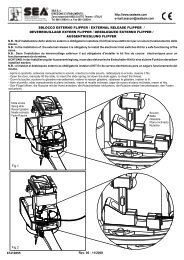
Sistemi Elettronicidi Apertura Porte e Cancelli®EnglishUSER 2 - <strong>24V</strong> <strong>DG</strong>International registered trademark n. 804888SELFLEARNING AND DEFAULT PARAMETERSThe control unit is pre-set with the default settings, to start the control unit with theDEFAULT settings just keep pressed the UP and DOWN buttons at the same time powersupplying the control unit the display shows the message init.The DEFAULT settings are shown in the Menues table.WORKING TIMES SELF LEARNINGNote1: Put a jumper on SAFETY E<strong>DG</strong>E contact if not used.Fig. 1Note2: It is not necessary to put a jumper on the limit switches, photocells and Stop if theyare not used.1) Check the right operation of the accessories (photocells, buttons etc.).If necessary set the leaf delay.2) If necessary adjust the selflearning speed.3) Switch off power supply (Fig. 1), release the motors (Fig. 2-3) and manually place the leaf onthe middle of the stroke (Fig. 4).Restore the mechanical lock (Fig. 5-6)4) Power the control unit (Fig.7)5) Choose the desired motor type; use (default Flipper).6) Select prog on the display, press OK and then UP and DOWN to start the programming.Note3: If on single leaf mode set MONO on ON.Note4: If one or both motors start in opening, switch off power and invert the motor(s) cable starting in opening.Afterwards repeat the procedure starting from point 4, or activate IN. T.7) Both leaves will start a CLOSE - OPEN - CLOSE cycle automatically (CLOSE M2 - CLOSE M1 - OPEN M1 -OPEN M2 - CLOSE M2 - CLOSE M1).End of selflearning.UFOBETAFLIPPERFig. 4Fig. 8ReleaseFig. 2OperatorreleasedFig. 3M1M2M1M2LockBETAFLIPPERAFig. 9NOFig. 5OperatorlockedFig. 6Fig. 7M1M267410756REV 01 - 07/20127
®Sistemi Elettronicidi Apertura Porte e CancelliInternational registered trademark n. 804888u.001UDOWNotUPEnglishSELECTION OF THE SETTINGSOKUPUPUPSl dTRAIbarrDOWNOKDOWNOKDOWNOKUSER 2 - <strong>24V</strong> <strong>DG</strong>The settings of the control unit are made through the UP, DOWN and OK buttons. The UP and DOWN buttons to scroll throughthe MENUS and SUBMENUS. By pressing OK you enter from MENU into SUBMENU and confirm the choice.Pressing the UP and DOWN buttons at the same time you access the SP MENU for special settings. Pressing the OK button for5 seconds, you enter the TEST MENU, where you can check the operating status of all inputs.Initial systemSoftware VersionProgramming exampleDISPLAYMENU <strong>SEA</strong> SETstrtMENUstrtstoppedoedgEPko.1Pko.2F o.iMENU FUNCTION board USER 2 <strong>24V</strong> <strong>DG</strong> INPUT TESTS(To access the Menu for input TESTS keep pressed OK for about 5 seconds)DescriptionDescriptionThe contact must be a N.O. Contact . When activating the related commandStart teston the display SET lights up, the input works.If SET is always on, check the wirings.Stop testPedestrian start testSafety edge testPhotocell 1 testPhotocell 2 testM1 opening limit switch testThe contact must be a N.C. Contact. If activating the related command on the displaySET lights up, the input works.If SET is always on, make sure that the contact is a N.C. ContactThe contact must be a N.O. Contact . When activating the related commandon the display SET lights up, the input works.If SET is always on, check the wirings.The contact must be a N.C. Contact. If activating the related command on the displaySET lights up, the input works.If SET is always on, make sure that the contact is a N.C. ContactThe contact must be a N.C. Contact. If activating the related command on the displaySET lights up, the input works.If SET is always on, make sure that the contact is a N.C. ContactThe contact must be a N.C. Contact. If activating the related command on the displaySET lights up, the input works.If SET is always on, make sure that the contact is a N.C. ContactThe contact must be a N.C. Contact. If activating the related command on the displaySET lights up, the input works. If SET is always on, makesure that the contact is a N.C. contact or that the related limit switch is not occupied.F .1F o.2F .2M1 closing limit switch testM2 opening limit switch testM2 closing limit switch testThe contact must be a N.C. Contact. If activating the related command on the displaySET lights up, the input works. If SET is always on, makesure that the contact is a N.C. contact or that the related limit switch is not occupied.The contact must be a N.C. Contact. If activating the related command on the displaySET lights up, the input works. If SET is always on, makesure that the contact is a N.C. contact or that the related limit switch is not occupied.The contact must be a N.C. Contact. If activating the related command on the displaySET lights up, the input works. If SET is always on, makesure that the contact is a N.C. contact or that the related limit switch is not occupied.0.0 Batteries’ voltage level Batteries charge level indicator867410756REV 01 - 07/2012
UUotUonoLogT.paPrgUSt.prEndNSt.Ps®Sistemi Elettronicidi Apertura Porte e CancelliInternational registered trademark n. 804888stpdU.EstStopdel.Del.ssu.albetaFl pFieldOn Offa toNp.p.1p.p.22p lNs uNO.prD sb1,2,3offonOff onOff onEnglishSELECTION OF THE SETTINGSMENU Description SET DescriptionTrs Transmitterstrt StartMotor typeLeaf settingWorking logicsTime of pauseStart in pauseSelflearning timesTest startExit menuMENU FUNCTIONS TABLE USER 2 <strong>24V</strong> <strong>DG</strong>Pedestrian StartExp. outputStopDelete TXDelete single transmitterSurf - Alpha motorsBeta motorsFlipper motorsField motorsIn ON activates single leaf modeAutomaticStep by step type 1Step by step type 2Two buttonsSafetyDead manOFF (semi-automatic logics)Setting from 1s to 4min.Start is not acceped during pauseStart is accepted during pauseTimes learning startUSER 2 - <strong>24V</strong> <strong>DG</strong>Default Set valuestrtstpdFl pOffautoD sbStart commandoffSelect END and press OK to exit the menu.The menuswitches off automatically after 2 minutesNote: On the USER 2 24GV <strong>DG</strong> Hydro (cod. 23024080) will change only the viusalizations of the "Typeof motor" menu.67410756 REV 01 - 07/20129
10DOWNUP®Sistemi Elettronicidi Apertura Porte e CancelliInternational registered trademark n. 804888EnglishSELECTION OF THE SETTINGS67410756 REV 01 - 07/2012USER 2 - <strong>24V</strong> <strong>DG</strong>PRESS AT THE SAME TIME FOR 5 SECONDS TO ENTER OR TO EXIT THE SPECIAL MENUSPECIAL MENU FUNCTIONS TABLE USER 2 <strong>24V</strong> <strong>DG</strong>(To enter the Special Menu keep pressed UP and DOWN at the same time for 5 seconds.To exit the Special Menu pressed END or keep pressed UP and DOWN at the same time for 5 seconds)MENU SP Description SET Description Default Set valueSp. 1 Motor M1 speed30 100 Motor M1 speed75Sp. 2 Motor M2 speed30 100 Motor M2 speed75Sl.dn Slowdown speed30Sp.lr Learning speed30 100 Learning speed50Beep BuzzerN. T Motors and limit-switch inversion off Synchronized right motoroffUUUtr.optr.cl.Op1L1.Op2L2Pu OuR.strSd.o1Sd.c1Sd.o2Sd.c2Lg.bu.PushOverD sb 6D sb 200 1000 1000 1000 100DisbOp.clO.opeO.cloD sb 3D sb 50D sb 50D sb 50D sb 50alysLa pUspyOpening torque M1and amperometric sensitivityNote: By increasing the torquethe sensitivity decreaseson Synchronized left motorEnc Encoder activation On Off In On enables the Encoder reading Off3370D sbD sbpr.bl. Pre-flashingD sb OFFD sb1,2,3 Adjustable from 1s to 5sNLeaf delay setting in openingLeaf delay setting in closingM1 opening torqueM1 closing torqueM2 opening torqueM2 closing torqueReversing StrokeM1 opening slowdownM1 closing slowdownM2 opening slowdownM2 closing slowdownFlashing lamp or Buzzer outputl.onSetting from OFF to 6 secondsFrom OFF to 20 seconds settingClosing torque M1and amperometric sensitivityNote: By increasing the torquethe sensitivity decreasesOpening torque M2and amperometric sensitivityNote: By increasing the torquethe sensitivity decreasesClosing torque M2and amperometric sensitivityNote: By increasing the torquethe sensitivity decreases70707030303030La pL. O Courtesy lightY l Only during cycle active.Y l1,2,3 Courtesy light setting from1s to 4min.Ped.o Pedestrian opening 20 100 Pedestrian opening space adjustment 100OFFOpening an closingOpening onlyClosing onlyFrom OFF to 3 secondsFrom OFF to 50% of the strokeFrom OFF to 50% of the strokeFrom OFF to 50% of the strokeFrom OFF to 50% of the strokeOnly before closingFlashing lamp always onClassic flashing lightControl lampU
DOWNUP®Sistemi Elettronicidi Apertura Porte e CancelliInternational registered trademark n. 804888EnglishSELECTION OF THE SETTINGSUSER 2 - <strong>24V</strong> <strong>DG</strong>MENU SP Description SET Description Default Set valueP.ped Pedestrian PausestrtPedestrian opening pause sameas for total openingstrtD sb OFFS.StrY lN. Yt rUs.edgPk.iPk.2PRESS AT THE SAME TIME FOR 5 SECONDS TO ENTER OR TO EXIT THE SPECIAL MENUSPECIAL MENU FUNCTIONS TABLE USER 2 <strong>24V</strong> <strong>DG</strong>(To enter the Special Menu keep pressed UP and DOWN at the same time for 5 seconds.To exit the Special Menu pressed END or keep pressed UP and DOWN at the same time for 5 seconds)Soft StartSetting from 1s to 4 min.Acceleration rampeOFFNumber of cycl. for maintenance100 10e4 Setting from 100 to 100000Number of executed cycles 0 10e9 Note: To reset keep pressedOK for 5 s.Timer management D sb OFFSafety edgePhotocell 1 managementPhotocell 2 management1,2,30 99D sbpk2PedD sb8.2LosOpenStopParL.iL.iUrp.paLosopenstopParUrp.paTimer function ON on photo2 inputTimer function ON on pedestrianinputEdge is ON but not protectedEdge is ON and protected bya 8k2 resistorPhotocell ON in closingPhotocell ON in openingand closingPhotocell ON also before openingPhotocell stops in closing andcloses when freePhotocell gives a command forimmediate closing during pauseand openingPhotocell pausing time loadingPhotocell ON in closingPhotocell ON in openingand closingPhotocell ON also before openingPhotocell stops in closing andcloses when freePhotocell gives a closing commandduring opening, pauseand closingPhotocell pausing time loading75I0e4D sbD sbLosOpen24ua<strong>24V</strong>aux output managementalysOp. LopenLosPa sNpk.te<strong>24V</strong>aux output always power supplied<strong>24V</strong>aux output power supplied onlyduring opening and closing<strong>24V</strong>aux output power supplied onlyduring opening<strong>24V</strong>aux output power supplied onlyduring closing<strong>24V</strong>aux output power supplied onlyduring pause<strong>24V</strong>aux output for connection ofphotocell TX to autotest67410756REV 01 - 07/201211
DOWNUP®Sistemi Elettronicidi Apertura Porte e CancelliInternational registered trademark n. 804888EnglishSELECTION OF THE SETTINGSUSER 2 - <strong>24V</strong> <strong>DG</strong>MENU SP Description SET Description Default Set valuepk.ePhototest economyOutput for Self-test ON onlyduring the operation of the motors.Re.sp Space retrieve0 15Retrieves the inertia of themotor after Stop or reversing 6from 0% to 15 %After reading the limit switch in closingR. Ot Reversing on limit switch D sb 3 the motor inverts for the set time, D sbadjustable from 0 to 3sec.UPo.Prall.rT.serL.tiUD agph.teTl.o1Tl. 1Tl.o2Tl. 2s.op1S. l1s.op2S. l2Ps.rdENDPRESS AT THE SAME TIME FOR 5 SECONDS TO ENTER OR TO EXIT THE SPECIAL MENUSPECIAL MENU FUNCTIONS TABLE USER 2 <strong>24V</strong> <strong>DG</strong>(To enter the Special Menu keep pressed UP and DOWN at the same time for 5 seconds.To exit the Special Menu pressed END or keep pressed UP and DOWN at the same time for 5 seconds)Periodic Push OverAntiintrusion alarmElectrolockrelease timeCourtesy light managementwith timerEvents diagnosticAuto-test photocellsTolerance between stop andobstacle motor 1 openingTolerance between stop andobstacle motor 1 closingTolerance between stop andobstacle motor 2 openingTolerance between stop andobstacle motor 2 closingSensitivity on obstacleSensitivity on obstacleSensitivity on obstacleSensitivity on obstacleEnter passwordExit special menuD sb 8D sbO. LoO.OpeOp. LD sb 5offon0 10ph.i2ph.iph.20 1000 1000 1000 1000 990 990 990 99----Allows the repetition of the Pushoverfunction at a distance of time adjustable D sbfrom 0 to 8 hours at hourly intervalsIf the limit switch is freed manuallyD sbit forces the reclosing of the gateOnly on closing limit switchOnly on opening limit switchOn limit switch in closingand in openingSets the lock releasetime from 0 to 5 s1When timer is ON the courtesy lightoffcan be kept switched OFFWith timer ON courtesy light canbe kept ONShows last event(See alarms table)Auto-test active on Photo1 and Photo2Auto-test active only on Photo1ph.1.2Auto-test active only on Photo2Adjusts the tolerance between stop 0and obstacleAdjusts the tolerance between 0stop and obstacleAdjusts the tolerance0between stop and obstacleAdjusts the tolerance between 0stop and obstacleAdjusts the revesing sensitivity onmotor 1 in opening.D sbNote: Only with Encoder On active.Adjusts the revesing sensitivity onmotor 1 in closing.D sbNote: Only with Encoder On active.Adjusts the revesing sensitivity onmotor 2 in opening.D sbNote: Only with Encoder On active.Adjusts the revesing sensitivity onmotor 2 in closing.D sbNote: Only with Encoder On active.Allows the entering of a passwordblocking the control unit parametersmodification (see page 18)Select END and press OK to exit the special menu.The special menu switches off automatically after 20 minutes.1267410756REV 01 - 07/2012
®Sistemi Elettronicidi Apertura Porte e CancelliInternational registered trademark n. 804888EnglishSAFETY E<strong>DG</strong>EIt is possible to connect an active safety edge on the terminal CN1. If thisdevice is pressed it opens the contact causing a partial inversion of themovement both in opening and in closing. If not used bridge the contacts 9and 11 of CN1. Note: contact N.C.CN19 10 11 12 13Common<strong>24V</strong> (FL)USER 2 - <strong>24V</strong> <strong>DG</strong>START - STOP - PEDESTRIAN START - ANTENNA -PHOTOCELL - E<strong>DG</strong>EPhotocell 1 and Photocell 2 Connections+ = <strong>24V</strong>(FL) COM = 0V PH1 = Photocell contact 1 PH2 = Photocell contact 2Note1: For the autotest connect the TX to the <strong>24V</strong>aux clamp and activate the Autotest function.Note2: The Ph.e will keep the photocells OFF while the gate is closed, thus saving energy.Note3: On the Ph.Te menu you can also activate the self-test even on the single photocell.The standard setting of the photocell 1 is FOTO CLOSE and the one of the photocell 2 is FOTOOPEN. The photocell 2 can be set also as TIMER (see TIMER function).The selftest can be applied also on single photocell.OPTIONS ON FOTO1 and FOTO2 adjustable on on- board display or with JOLLY terminal.FOTO CLOSE activation ( Los): if occupied, reverses the movement in closing, during pause itprevent the closing.Activation repeat pause (rP.PA): If occupied, during pause it recharges the timer of pause. Inclosing it reverses the movement.FOTO OPEN activation (oPEn): If activated the photocell blocks the movement as long as it’sbusy, when released the opening continues.FOTO PARK activation ( Par ): in opening it is not active; in pause are activated it commands theclosing when released, otherwise it’s not active; in closing it stops the movement as longas it is busy, when released the closing continues.FOTO STOP activation (STOP): When activated before the opening the photocell blocksthe automation as long as it is busy, during the opening it will be ignored. In closing theintervention of the photocell causes the reopening.Activation PHOTO CLOSE IMMEDIATELY: The photocell stops the gate as long as it isoccupied in both opening and closing, when released it gives a closing command(Closing one second after release of the photocell ).Options <strong>24V</strong>aux can be set with on-board Display or with Jolly device.It is possible to chose when having tension on the <strong>24V</strong>aux output. The options are:always, only during opening, only during cycle, only before opening or only during pause.PEDESTRIAN START (N.O.) The pedestrian start can beconnected between the clamps 2 and 4 of the CN1 terminal .This input allows a partial opening the opening space can be setthrough the on-board display or through the JOLLY device.Note1: The contact for partial opening is a N.O. Contact (Normallyopen).Note2:In 2 BUTTONS logic it is necessary to keep pressed the StartPed. to re-close the automation.Note3: In dead man logic this button executes the re-closing if youkeep it pressed.Note4: When closed during pause, the gate will reclose only afterthis input has been reopened.TIMER activation: This input can be transformed into TIMER (SeeTIMER).911SafetyedgeAntenna1CN11 2 3 4 5 6 7 81211Common2RX1Start31211Start ped.4RX2Stop51211Common666TX1Photocell 171211Photocell 28TX2STOP (N.C.) The STOP is connected between the clamps 2 and 5 of the CN1 terminal .The pressure on this button immediately stops the motor in any condition/position. A start command is needed to re-start the movement.After a stop the motor always re-starts in closing.START (N.O.) The START is connected between the clamps 2 and 3 of the CN 1 terminal.An impulse given to this contact opens and closes the automation depending onthe selected logic it can be given by a key switch, a keypad,etc. To connect the other devices refer to the related instructions leaflets. (ie. loop detectors and proximity switches).Note1: In DEAD MAN logic it is necessary to keep pressed the Start for the opening of the automation.Note2: In 2 BUTTONS logic this button performs the opening.TIMER67410756Can be activated through on-board display or through the Jolly programmer. In both cases it’s a N.O. contact which provoques the opening of theautomation keeping it open until it is activated. When it’s released, the gate attends the set pausing time and executes the reclosing. The TIMERcommand can be activated on the inputs FOTO2, START PEDESTRIAN.Note1: When activated on the pedestrian entry, the pedestrian will be disabled also on the radio transmitter.Note2: In case of intervention of a security device during the timer (Stop, Ammeter, Edge), to restore the movement it will be necessary to give astart impulse.Note3: In case of no power supply with open gate and active Timer the control unit will restore its use, otherwise if during restore of the powersupply the TIMER is not activated it will be necessary to give a start impulse for the reclosing.REV 01 - 07/201213
®Sistemi Elettronicidi Apertura Porte e CancelliInternational registered trademark n. 804888EnglishUSER 2 - <strong>24V</strong> <strong>DG</strong>SAFETY GATE OR AMPEROMETRIC MANAGEMENTAMPEROMETRIC DEVICE FOR ELECTROMECHANICAL OPERATORSThis control unit comes with an obstacle detection system working only on electromechanical operators allowing tohave the reversing on obstacles and the automatic detection of the stops.The sensitivity is adjustable for single leaf and single opening and closing direction through the torque parameter.SAFETY GATEThe Safety Gate is an ENCODER allowing the detection of the gate positionand its reversing in case of obstacles. To use the ENCODER it is necessaryto enable it inside the special ENC Menu. The sensitivity on the obstacle isadjustable from 0 - 99%. The higher the percentage is the more it will bedifficult to detect the obstacle.CN71 2 3 4+<strong>24V</strong> ENC1 ENC2 GNDATTENTION: The firstoperation after power failure, willbe executed with the set speedto search the mechanical stopslimit.SAFETY GATE 1 1SAFETY GATE 2123 434ELECTRO- LOCK AND WARNING LAMP1 2 3 4 5 6 7 8 913WARNING LAMPCN2TIMEABLE COURTESYLIGHT OUTPUTMax 500 mACN1ELECTRO- LOCK1 2 3 4 5 6 7 8 9 10 11 12 13126789Electro-lock exitAn electro-lock of 12V 15W max can be connected. It ispossible to disactivate the electroc-lock if not used. Thisoperation allows to save energy of the control unit. Therelease of the electro-lock can be timed’ from 0 to 5 s.Flashing Lamp <strong>24V</strong> 15W (Warning lamp ) /<strong>24V</strong> 4W LedThe warning lamp advises that the automatic gate is inmovement performing 1 flash /second in opening and 2flashes / second in closing. Instead it remains turned on fixduring pause.To connect it, connect the wires of the warning lamp asshown in the figure. Note: It is recommended to use theflash <strong>24V</strong> Led.Pre-flashing form 0 to 5 seconds can be activated beforeoperator start or only before closing.Furthermore from the flashing lamp it is possible to verifysome alarm signals. See alarms indications.It is possible to set this exit with fixed flashing also when thegate is not moving or it is possible to change this exit intocontrol lamp. In such case all the indications of alarmremain on the warning lamp as long as they are active.1467410756REV 01 - 07/2012
®Sistemi Elettronicidi Apertura Porte e CancelliInternational registered trademark n. 804888EnglishLIMIT SWITCHLimit switchIf not connected they don't have to be bridged.For the limit switch function the presence of the limit switches inboth closing and opening is necessary. In case of single leavesit is not necessary to bridge the limit switch of the motor 2.It is possible to activate the function anti-intrusion. Limit switch,that if released, forces the motor to re-close.! For the right function of the limit switches theremust be a corrsipondence between the direction ofmovement of the motors and the respective occupied limitswitches.Com = CommonC = ContactUSER 2 - <strong>24V</strong> <strong>DG</strong>CN21 2 3 4 5 6 7 8 9OpeningLimit Switch M1N.C.51ClosingLimit Switch M1N.C.52OpeningLimit Switch M2N.C.53ClosingLimit Switch M2N.C.54EXTERNAL RECEIVERExample: Connection of aradio receiverFor the connection of thereceiver refer to the relativeinstructions manual.CN11 2 3 4 5 6 7 8 9 10 11 12 13+ -234101167410756REV 01 - 07/201215
®Sistemi Elettronicidi Apertura Porte e CancelliInternational registered trademark n. 804888EnglishUSER 2 - <strong>24V</strong> <strong>DG</strong>RADIO TRANSMITTER SELF LEARNINGWITH RECEIVER ON BOARD OF CONTROL UNIT!WARNING: Make the radio transmitters programming before you connect the antenna and insert the receiver into thespecial CMR connector (if available) with turned off control unit. (The control unit automatically recognizes if the receiver is a RF, RFRoll, RF Roll Plus or RF UNI module).With RF Roll or RF Roll Plus module it will be possible to use only Coccinella Roll or Coccinella Roll Plus radio transmitters. or SmartDual Roll or Smart Dual Roll Plus.With the RF UNI module it will be possible to use both the transmitters of the Roll Plus series and those with fixed code. The firstmemorized transmitter determines the type of the remaining radio transmitters.Select through the display TrS and press OK, now select with the UP and DOWN buttons, the command to which you want to associate thebutton (it is possible to associate max. 2 commands) and press OK to confirm the choice, now press the button of the radio transmitter whichyou want to associate. If the storage is successful, the display will show E .If the receiver is a Rolling Code, press twice the button of the radio transmitter that you want to program to memorize the first TX.In the TrS MENU it is possible to select Strt (to associate a Start command), StPd (Pedestrian Start ), .Est(For the activation of a contacton the EXP output), StoP (To associate the STOP command to the TX), dEL. (To delete all TX), del.s (To delet the single transmitter only if it is aRolling Code Plus).UUNotes:- Enter radio transmitters learning only when the working cycle stops and the gate is closed.- If the radio transmitters are Rolling Code it’s possible to memorize up to 800 codes (buttons).- If the radio transmitters are with fixed code it will be possible to memorize up to max. 30 codes (buttons).- You can store max. 2 of the available 4 functions. If the control unit receives a code which was already associated to another function it will beupdated with the new function.UUUDELETE TRANSMITTERS FROM THE RECEIVERWith modules different from RF UNI, it will be possible to delete only the entire memory of the receiver.Proceed as follows: select from the menu TrS DEL and hold the OK button until the display shows the message DONE.With the RF UNI module, it will be possible to also delete the single button of the transmitter.It can be done in two ways:1) If you have the transmitter, or if you are using transmitters with fixed code, the cancellation can be executed by simply retransmitting thecode. Ex. Button 1 of the transmitter memorized as START; access the menu TrS press OK, select STRT, press OK.Send a STRT command from the transmitter and on the display will show DEL.At this point the single button results deleted.2) If you do not have a transmitter, or you are using a Roll Plus transmitter, you can delete the transmitter selecting the serial number of thetransmitter to be deleted.Procede as follows: Access the menu TrS , press OK, select DELS, press OK, choose the memory location to be deleted through the UP andDOWN buttons, press OK, check on the display if the serial number of the transmitter to be deleted is the right one, press OK, on the displayshows SURE, if the transmitter to be deleted is the right one press OK, otherwise press the DOWN button to return to the menu TrS .UUNote: When using Roll Plus transmitters, it is recommended to record on a table similar to the below example, the serial number associatedingit to the memory location where it was stored.UUTABLEEXAMPLE67410756MemorylocationTransmitterbutton012345678910111213141516171819201 2 3 4REV 01 - 07/2012Serial numberCustomer17
®Sistemi Elettronicidi Apertura Porte e CancelliInternational registered trademark n. 804888EnglishFUNCTION LOGICUSER 2 - <strong>24V</strong> <strong>DG</strong>AUTOMATIC LOGICA start impulse opens the gate. A second impluse during the opening will not be accepted.A start impulse during closing reverses the movement.NOTE 1: To have the automatic closing it is necessary to set a pause time, otherwise all the logic will be semi-automatic.NOTE2: It is possible to choose, whether to accept or not, the start in pause, selecting in the MENU the item ST.PS and choosing ONor OFF. By default, the parameter is OFF.SECURITY LOGICA start impulse opens the gate. A second impulse during opening reverses the movement.A start impulse during closing reverses the movement.NOTE 1: To have the automatic closing it is necessary to set a pause time, otherwise all the logic will be semi-automatic.NOTE2: It is possible to choose, whether to accept or not, the start in pause, selecting in the MENU the item ST.PS and choosing ONor OFF. By default, the parameter is OFF.STEP BY STEP TYPE 1 LOGICThe start impulse follows the OPEN-STOP-CLOSE-STOP-OPEN logic.NOTE 1: To have the automatic closing it is necessary to set a pause time, otherwise all the logic will be semi-automatic.NOTE2: It is possible to choose, whether to accept or not, the start in pause, selecting in the MENU the item ST.PS and choosing ONor OFF. By default, the parameter is OFF.STEP BY STEP TYPE 2 LOGICThe start impulse follows the OPEN-STOP-CLOSE -OPEN logic.NOTE 1: To have the automatic closing it is necessary to set a pause time, otherwise all the logic will be semi-automatic.NOTE2: It is possible to choose, whether to accept or not, the start in pause, selecting in the MENU the item ST.PS and choosing ONor OFF. By default, the parameter is OFF.DEAD MAN LOGICThe gate opens as long as the START button of opening is pressed; releasing it the gate stops. The gate closes as long as the button connectedto the PEDESTRIAN START is pressed; releasing it the gate stops. To execute complete opening and/or closing cycles the relatedpushbuttons must be constantly pressed.2 PUSHBUTTONS LOGICOne start opens, one pedestrian start closes. In opening the closing will not be accepted. In closing a start command reopens, a pedestrian startcommand (closes) will be ignored.PASSWORD ENTERING MANAGEMENTWith a new control unit all menus can be displayed and set and the password will be disabled.Selecting one of the Menus and keeping UP and DOWN pressed at the same time for 5 seconds, you will access the SP Menu containing thePS.rd. Submenu.Pressing OK in the PS.rd. Menu, you will proceed with the entering of the numeric code of the 4-digit PASSWORD.Use UP and DOWN to increase or decrease the number, press OK to confirm it and you will pass automatically to the entering of the nextnumber. Pressing OK after the last entered number the word SURE appears, confirm the activation of the PASSWORD and the message DONEappears, pressing UP or DOWN instead you can cancel the operation and NULL will appear on the display.Once entered the PASSWORD, it will be definitively activated, once the display switch off timeout has expired, or by turning off and on again thecontrol unit. Once the PASSWORD has been activated, the menus of the display can be only displayed but not set. To unlock them you mustenter the correct PASSWORD in the PS.rd menu, if the password is wrong the message ERR will appear.At this point, if the password has been entered correctly, the menus will be unlocked and it will be possible to change the parameters of thecontrol unit again.If the control unit has been unlocked through PS.rd. Menu, it is possible to enter a new and different password, using the same entering processas for the first one; at this point, the old password will no longer be valid.If the password has been forgotten, the only way to unlock the control unit is to contact the <strong>SEA</strong> technical assistance, which will assess whetherto provide the procedure to unlock the control unit or not.Note: The password cannot be set through the Jolly terminal.1867410756REV 01 - 07/2012
®Sistemi Elettronicidi Apertura Porte e CancelliInternational registered trademark n. 804888EnglishUSER 2 - <strong>24V</strong> <strong>DG</strong>PROGRAMMER JOLLY PARAMETERS ADJUSTMENTThe JOLLY programmer allows to keep under control and to change all parameters of the control unit without need to use thebuttons of the control unit. Compared to the on-board display, the programmer allows to view the programming instructions inthe user's language and in a non-encrypted way. In addition to the JOLLY programmer, the user can work comfortably standingup without looking at the control unit.Screen 1Language: ITScreen 2MotorEncSpeed1Speed2Available languages: IT,EN,FR,ES [ Italian, English, Spanish, French][Field, Alpha/Surf, Beta/FlipSp, Flipper]Encoder [on/off][30÷100 ] motor 1 speed adjustment[30÷100 ] motor 2 speed adjustmentThe arrowindicates that theparameter can bechanged with the +and - buttons.Screen 3Slow SpeedLearn speedSp.Decel.O1Sp.Decel.C1[30÷100 ] slowdown speed adjustment[30÷100 ] selflearning speed adjustment[Off÷100 ] motor 1 slowdown space in opening adjustment[Off÷100 ] motor 1 slowdown space in closing adjusmtentScreen 4Sp.Decel.O2Sp.Decel.C2SoftStartTorque op.M1[Off÷100 ] motor 2 slowdown space in opening adjustment[Off÷100 ] motor 2 slowdown space in closing adjustment[0÷100 ] adjusts the acceleration ramp[10÷100]% (max. motors current)Screen 5Torque cl.M1Torque op.M2Torque.cl.M2Cycle[10÷100]% (max. Motors current)[10÷100]% (max. Motors current)[10÷100]% (max. Motors current)[Secur./auto/deadman/step1/step2/two buttons]Screen 6Double leaf / Single leafPause time [0÷240]s (pausing time in seconds, 0s halfautomatic logic)LearningTimes learning [On-Off]Cycles [0÷... ] (Number of executed cycles )Screen 7PedestrianOpen delayClose delayAnti Intrusion[30÷100]% (Pedestrian opening rate)[Off÷6s]% (Leaf delay in opening)[Off÷20s]% (Leaf delay in closing)[Off,Open,Close.,op.cl.] (Implies the presence of a N.C. contact onlimit switch which if released forces the motors in closing)Screen 8Preblink [Close, Off, 0÷5s] (Only before closing, OFF from 0 to 5s)Light Time [Cycle, Off, 0÷240s] (Only during cycle, OFF from 0 to 240s)Ph.test[1,2-1-2] (Only on Foto1, only on Foto2, on both)Max Cycles[100÷100000] (Number of cycles for maintenance)67410756 REV 01 - 07/201219
®Sistemi Elettronicidi Apertura Porte e CancelliInternational registered trademark n. 804888EnglishUSER 2 - <strong>24V</strong> <strong>DG</strong>PROGRAMMER JOLLY PARAMETERS ADJUSTMENTScreen 9FlashPhoto1Photo28k2 edge[Normal/Control/always/beep][Close/Open/stop/park/close imm./rel.pause][Close./Open/stop/park/close imm./rel.pause][On-Off] (On ON it allows to connect a balaced edge with 8k2resistance)Screen 10TimerPos. Recovery<strong>24V</strong> auxStart pause[OFF-Ped-Foto2] (Allows the timer activation on the Foto2 orpedestrian input)[0÷100]% (Percentage of position recovery)[Cycle/in open /in clos./pause/ph.test/ph.T.ECO/always][ON/OFF] (On ON and if the autom. clos. is on ON a start willcause the immediate closure of the gate)Screen 11Mot.inv.StartRev. Mot.P.Ped[ON/OFF] (Allows to changes at the same time the limit switchand the direction of motor rotation without disconnecting the cables)[ON/OFF] (Equivalent to giving a test start)[0÷100%] (Activates an inversion at the end of closing)[start, Off, 0÷240 sec] (Differenciates the pedestrian pause from thetotal one)Screen 12Tl.op.1Tl.cl.1Tl.op.2Tl.cl.2[0÷ 100%] (Tolerance between stop and obstacle)[0÷ 100%] (Tolerance between stop and obstacle)[0÷ 100%] (Tolerance between stop and obstacle)[0÷ 100%] (Tolerance between stop and obstacle)Screen 13Push ov.Leaf StrokeP.O.PR.Lock[Off,open., close.,Open.cl.] (Activates the motors at max. torqueat the end of closing or opening or in both cases)[0÷3 sec] (Facilitates the electrolock release)[0÷8 ore] (Activates the periodic Push Over with stoped motors)[0 a 5s] (Activates the click of the lock from 0 to 5 seconds)Screen 14L.Timer[Off-On] Allows to keep switched on or off the control light if a Timeris activeScreen 15EventSummarizes the last 10 events that occurred on the unit2067410756 REV 01 - 07/2012
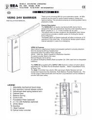
®Sistemi Elettronicidi Apertura Porte e CancelliInternational registered trademark n. 804888EnglishUSER 2 - <strong>24V</strong> <strong>DG</strong>CONNECTION OF BATTERIES TO BATTERY CHARGER CARDNOTE:On the test menu it ispossible to see batteriescharge level.Cod.23101110= charge ~ 200mA= charge ~ 360mA(BAT)28V Battery chargerPositiv e batteryNegative batte ry charger+S-CN1= charge ~ 800mAGND GND PSOL BAT 28V+S -Solar Panel+GNDUSER 2<strong>24V</strong> <strong>DG</strong>Battery current (mA)800Battery (Ah)12 or 16- +- +360712V12V2002Flashings Number92364BatteriesALARMS INDICATIONSKind of alarmMotors faultPhotocell in closingPhotocell in openingOpening impactSafety edgeFlashings Number5764 fastALARM SIGNALSInsert two 12V batteries connected in series.Signals Kind of alarm SolutionsFAULMotors current faultSure there are no short circuits on the motor or on the control unit.FT.24<strong>24V</strong> Power supply fault Make sure there are no short circuits on the wiring or on the control unit andno overloads.FT.AU<strong>24V</strong>aux output voltage Make sure there are no short circuits on wiring or control unit andno overload.FT.LIPower supply faultCheck the network or the F1 fuse.F.BATBattery voltage faultIf network is not presentF.E<strong>DG</strong>Balanced edge input fault Check for a 8.2 Ohms resistive value on the edge input, if not availableenter it, or disable the reading of the 8k2 in the special menu.F.PHOSelf-test photocells fault Check the photocells operation and / or connections on the control unit.FT.fLimit switch activation fault Check the operation of both limit switches and / or correspondencebetween movement direction of the motor and engaged limit switches.FT.FLY LFlashing lamp faultMax. cyclesCheck connections and / or conditions of the lamp.Maintain and / or reset the number of performed cycles.Note: To exit from the error messages, press OK. If the error persists, make all required checks for the specific error and / or disconnect thedevice that generates the error to see if the error disappears.At each opening and closing of the automation the flashing light will blink. It blinks once per second during opening and twice per secondduring closing, while it remains lit during pause.It is possible to view the alarms also on the flashing light or on the control lamp, simply by observing the number of flashes emitted andverifying the reference in the table below:Kind of alarmStopMax. Reached cyclesClosing impactLimit switch errorPeriodically, in relation to the number of manoeuvre and the type of gate, it is recommended to execute, if the gate has modified the attritionsand it doesn't work, the re-programming of the times of learning on the electronic board.The 7 flashes refer to the attainment of the established maximum cycles for the maintenance of the control unit, therefore it is recommended toperform the maintenance and to put on zero the number of cycles.67410756REV 01 - 07/201221
®Sistemi Elettronicidi Apertura Porte e CancelliInternational registered trademark n. 804888AdvisesMake sure all Safety LED are turned ONAll not-used N.C. contacts must have jumpersEnglishUSER 2 - <strong>24V</strong> <strong>DG</strong>Problem Found Possibile Cause SolutionsMotor doesn’t respond to anySTART impulseGate doesn’t move while themotor is runningTROUBLE SHOOTINGa.) Jumper missing on one of the N.C. Contactsb.) Burnt fusea.) The motor is in the released positionb.) There is an obstaclea.) Check the connections or the jumpers on theconnections of the safety edge, of the stop andof the photocellb.) Replace the burned fuse on the control unitled 1 turned on.a.) Re-lock the motorb.) Remove obstacleGate doesn’t reach the completeOpen / Closed positionThe gate opens but doesn’tcloseThe gate doesn’t closeautomaticallya.) Wrong setting of the limit switchesb.) Error on programmingc.) Gate is stopped by an obstacled.) The fitting geometry is inadequatee.) Torque or speed too lowa.) The photocell contacts are not closedb.) Ammeter alarma.) Pause time set to highb.) Control unit in semi-autom. logica.) Set limit switchesb.) Repeat programmingc.) Remove obstacled.) Check fitting geometry following the operatorinstallation manuale.) Increase torque parametera.) Check the jumbers or the signals on the flashinglamp or on the dispalyb.) Check if the ammeter alarm has intervened andeventually increase the torque parameter.a.) Adjust pause timeb.) Adjust the automatic or security logicPage for both installer and userMAINTENANCEConsidering the number of working cycles and the kind of gate, if the gate has changed the clutches and doesn’t work it’s necessary toperiodically proceed, with the learning times reprogramming on the electronic control unit.Periodically clean the optical systems of the photocells.REPLACEMENTSAny request for spare parts must be sent to:<strong>SEA</strong> S.p.A. - Zona Ind.le, 64020 S.ATTO - Teramo - ItaliaSAFETY AND ENVIRONMENTAL COMPATIBILITYDisposal of the packaging materials of products and/or circuits should take place in an approved disposal facility.REGULAR PRODUCT DISPOSAL (electric and electronic waste)(It’s applicable in EU countries and in those ones provided with a differential waste collection)The brand that you find on the product or on documentation signals that the product must not be disposed off together with other domesticwaste at the end of life cycle. In order to avoid any possible environmental or health damage caused by irregular waste disposal, werecommand to separate this product from other forms of waste and to recycle it in a responsible way in order to provide the sustainable re-use ofmaterial resources. Domestic users are invited to contact the retailer where the product has been purchased or the local office in charge of allthe information related to differential watse collection and recycling of this kind of product.STORINGWAREHOUSING TEMPERATUREST min T Max Dampness min Dampness Max- 20°C + 65°C5% Not condensing 90% Not condensingMaterials handling must be made with appropriate vehicles..WARRANTY LIMITSFor the guarantee see the sales conditions on the official <strong>SEA</strong> price list.<strong>SEA</strong> reserves the right to make any required modification or change to the products and/or to this manual without any advanced noticeobligation.2267410756REV 01 - 07/2012
CONDIZIONI DI VENDITAEFFICACIA DELLE PRESENTI CONDIZIONI GENERALI DI VENDITA: Le presenti condizioni generali di vendita si applicano a tutti gli ordini indirizzati a <strong>SEA</strong> S.p.A. Tutte le vendite fatte da<strong>SEA</strong> ai clienti sono regolate secondo le presenti condizioni di vendita che costituiscono parte integrante del contratto di vendita ed annullano ogni clausola contraria o pattuizioni particolaripresenti nell’ ordine o in altro documento proveniente dall’ acquirente (cliente)AVVERTENZE GENERALI Gli impianti di automazioni porte e cancelli vanno realizzati esclusivamente con componenti <strong>SEA</strong>, salvo accordi specifici. L’inosservanza delle norme di sicurezzavigenti (Norm. EUROPEE EN 12453 - EN 12445 e altro) e di buona tecnica esclude la <strong>SEA</strong> da ogni responsabilità. La <strong>SEA</strong> non risponde del mancato rispetto della corretta e sicura installazionesecondo le norme.1) PROPOSTA D’ORDINE La proposta d’ordine si intenderà accettata solo dopo la sua approvazione da parte della <strong>SEA</strong>. Conseguenza della sua sottoscrizione, l’acquirente sarà vincolato allastipula di un contratto d’acquisto, secondo quanto contenuto nella stessa proposta d’ordine e nelle presenti condizioni di vendita. Viceversa, la mancata comunicazioneall’acquirentedell’aprovazione della proposta d’ordine, non comporta la sua automatica accettazione da parte della <strong>SEA</strong>2) VALIDITÀ OFFERTA Le offerte proposte dalla <strong>SEA</strong> o dalla sua struttura commerciale periferica, avranno una validità di 30 giorni solari, salvo diversa comunicazione in merito.3) PREZZI I prezzi della proposta d’ordine sono quelli del listino in vigore alla data della redazione della stessa. Gli sconti applicati dalla struttura commerciale periferica della <strong>SEA</strong> siintenderanno validi solo dopo la loro accettazione da parte della <strong>SEA</strong>. I prezzi si intendono per merce resa franco ns. stabilimento in Teramo, esclusi IVA ed imballaggi speciali. La <strong>SEA</strong> si riservail diritto di modificare in qualsiasi momento il listino, dando opportuno preavviso alla rete di vendita. Le condizioni speciali riservate agli acquisti con formula agevolata Qx, Qx1, Qx2, Qx3 sonoriservate ai distributori ufficiali dietro accettazione scritta da parte della direzione <strong>SEA</strong>.4) PAGAMENTI Le forme di pagamento ammesse sono quelle comunicate o accettate di volta in volta dalla <strong>SEA</strong>. Il tasso di interesse sul ritardo da pagamento è del 1,5% mensile e comunquenon oltre il tasso massimo legalmente consentito.5) CONSEGNA La consegna avverrà indicativamente ma non tassativamente entro 30 giorni lavorativi dalla data di ricezione dell’ordine, salvo diverse comunicazioni in merito. Il trasportodegli articoli venduti sarà effettuato a spese ed a rischio dell’acquirente. La <strong>SEA</strong> si libera dall’obbligo della consegna rimettendo la merce al vettore, sia esso scelto dalla <strong>SEA</strong> oppuredall’acquirente. Eventuali smarrimenti e/o danneggiamenti della merce dovuti al trasporto, sono a carico dell’acquirente.6) RECLAMI Eventuali reclami e/o contestazioni dovranno pervenire alla <strong>SEA</strong> entro 8 giorni solari dalla ricezione della merce, supportati da idonei documenti provanti la loro veridicità.7) FORNITURA L’ordine in oggetto viene assunto da <strong>SEA</strong> senza alcun impegno e subordinatamente alle possibilità di approvvigionamento delle materie prime occorrenti alla produzione;eventuali mancate esecuzioni totali o parziali non possono dar luogo a reclami e riserve per danni. La fornitura <strong>SEA</strong> è strettamente limitata alla sola merce di sua produzione, esclusi ilmontaggio, l’installazione ed il collaudo. La <strong>SEA</strong> declina pertanto ogni responsabilità per danni che dovessero derivare, anche a terzi, dall’inosservanza delle norme di sicurezza e della buonaregola d’arte nelle fasi dell’installazione e dell’impiego dei prodotti venduti.8) GARANZIA La garanzia minima è di 12 mesi e può essere estesa, come di seguito, in caso di riconsegna del certificato di garanzia.SILVER: Le parti meccaniche degli operatori rientranti in tale categoria sono garantite per 24 mesi dalla data di fabbricazione riportata sull’operatore.GOLD: Le parti meccaniche degli operatori rientranti in tale categoria sono garantite per 36 mesi dalla data di fabbricazione riportata sull’operatore.PLATINUM: Le parti meccaniche degli operatori rientranti in tale categoria sono garantite per 36 mesi dalla data di fabbricazione riportata sull’operatore. La garanzia di base (36 mesi) saràestesa per ulteriori 24 mesi (fino ad un totale di 60 mesi) qualora venga acquistato il certificato di garanzie che dovrà essere compilato e rispedito alla <strong>SEA</strong> S.p.A. entro 60 giorni dall’acquisto.L’elettronica e le centrali di comando sono garantite per 24 mesi dalla data di fabbricazione. Nell’eventualità di difettosità del prodotto, la <strong>SEA</strong> si impegna alla sua sostituzione gratuita oppurealla sua riparazione, previa restituzione al proprio centro di riparazione. La definizione di stato di garanzia è ad insindacabile giudizio della <strong>SEA</strong>. I pezzi sostitutivi restano di proprietà della <strong>SEA</strong>.In modo vincolante, il materiale dell’acquirente ritenuto in garanzia deve essere spedito al centro di riparazione della <strong>SEA</strong> in porto franco e sarà rispedito dalla <strong>SEA</strong> in porto assegnato. Lagaranzia non si estende alla manodopera eventualmente accorsa. I difetti riconosciuti non produrranno alcuna responsabilità e/o richiesta di danni, di qualsiasi natura essi siano, da partedell’acquirente nei riguardi della <strong>SEA</strong>. La garanzia non è in ogni caso riconosciuta qualora sia stata apportata alla merce qualsivoglia modifica, oppure vi sia stato un uso improprio, oppure si siain presenza di una qualsivoglia sua manomissione o di un montaggio non corretto, oppure se sia stata rimossa l’etichetta apposta dal produttore comprensiva del marchio <strong>SEA</strong> registrato n°804888. La garanzia non è inoltre valida nel caso la merce <strong>SEA</strong> sia stata in parte o in toto accoppiata a componenti meccanici e/o elettronici non originali, ed in particolare in assenza di unaspecifica autorizzazione in merito, ed inoltre nel caso in cui l’acquirente non sia in regola con i pagamenti. La garanzia non comprende danni derivati dal trasporto, materiale di consumo, avariedovute al mancato rispetto delle specifiche prestazionali dei prodotti indicate nel listino. Non è riconosciuto alcun indennizzo durante il tempo di riparazione e/o sostituzione della merce ingaranzia. La <strong>SEA</strong> declina ogni responsabilità per danni a cose o persone derivanti dall’inosservanza delle norme di sicurezza e della non conforme installazione o dall’impiego errato deiprodotti venduti. La riparazione dei prodotti in garanzia e fuori garanzia è subordinata al rispetto delle procedure comunicate da <strong>SEA</strong>.9) RISERVATO DOMINIO Sulla merce venduta è valida la clausola del riservato dominio, della quale la <strong>SEA</strong> deciderà autonomamente se avvalersi o meno, in virtù della quale l’acquirenteacquisisce la proprietà della merce, solo dopo che il suo pagamento sia stato completamente effettuato.10) FORO COMPETENTE Per qualsiasi controversia avente per oggetto l’applicazione di questo contratto, viene eletto competente il Foro di Teramo. La lingua valida nell’ interpretazione dicataloghi, manuali di installazione, condizioni di vendita o altro è quella italiana. La <strong>SEA</strong> si riserva la facoltà di apportare modifiche tecniche atte a migliorare i propri prodotti, presenti o meno inquesto Listino, in qualsiasi momento senza preavviso. La <strong>SEA</strong> declina ogni responsabilità derivante da possibili inesattezze contenute nel presente listino, derivanti da errori di stampa e/otrascrizione. Il presente Listino annulla e sostituisce quelli precedenti. L’acquirente ai sensi della legge 196/2003 (codice privacy) acconsente all’inserimento dei propri dati personali derivantidal presente contratto negli archivi informatici e cartacei della <strong>SEA</strong> S.p.A. al loro trattamento per motivi commerciali ed amministrativi.Diritti di proprietà industriale: il cliente, con l’acquisto, accetta le presenti condizioni di vendita e riconosce in capo a <strong>SEA</strong> la titolarità esclusiva del marchio internazionale <strong>SEA</strong> registrato n.804888 apposto sulle etichette dei prodotti e/o sui manuali e/o su ogni altra documentazione, e si impegna ad utilizzare il medesimo nella propria attività di rivendita e/o installazione secondomodalità che non ne riducano in alcun modo i diritti, a non rimuovere, sostituire o alterare marchi o altri segni distintivi di qualsiasi genere apposti ai prodotti.E’ vietata ogni forma di riproduzione o utilizzo del marchio <strong>SEA</strong> e di ogni altro segno distintivo presente sui prodotti, salvo autorizzazione scritta di <strong>SEA</strong> S.p.A..Agli effetti dell’articolo 1341 del C.C. si approvano specificatamente per iscritto le clausole di cui ai numeri:4) PAGAMENTI - 8) GARANZIA - 10) FORO COMPETENTETERMS OF SALESEFFICACY OF THE FOLLOWING TERMS OF SALE: the following general terms of sale shall be applied to all orders sent to <strong>SEA</strong> S.p.A. All sales made by <strong>SEA</strong> to all costumers are made underthe prescription of this terms of sales which are integral part of sale contract and cancel and substitute all apposed clauses or specific negotiations present in order document received from thebuyer.GENERAL NOTICE The systems must be assembled exclusively with <strong>SEA</strong> components, unless specific agreements apply. Non-compliance with the applicable safety standards (EuropeanStandards EM12453 – EM 12445) and with good installation practice releases <strong>SEA</strong> from any responsibilities. <strong>SEA</strong> shall not be held responsible for any failure to execute a correct and safeinstallation under the above mentioned standards.1) PROPOSED ORDER The proposed order shall be accepted only prior <strong>SEA</strong> approval of it. By signing the proposed order, the Buyer shall be bound to enter a purchase agreement, accordingto the specifications stated in the proposed order.On the other hand, failure to notify the Buyer of said approval must not be construed as automatic acceptance on the part of <strong>SEA</strong>.2) PERIOD OF THE OFFER The offer proposed by <strong>SEA</strong> or by its branch sales department shall be valid for 30 solar days, unless otherwise notified.3) PRICING The prices in the proposed order are quoted from the Price List which is valid on the date the order was issued. The discounts granted by the branch sales department of <strong>SEA</strong> shallapply only prior to acceptance on the part of <strong>SEA</strong>. The prices are for merchandise delivered ex-works from the <strong>SEA</strong> establishment in Teramo, not including VAT and special packaging. <strong>SEA</strong>reserves the right to change at any time this price list, providing timely notice to the sales network. The special sales conditions with extra discount on quantity basis (Qx, Qx1, Qx2, Qx3 formula)is reserved to official distributors under <strong>SEA</strong> management written agreement.4) PAYMENTS The accepted forms of payment are each time notified or approved by <strong>SEA</strong>. The interest rate on delay in payment shall be 1.5% every month but anyway shall not be higher thanthe max. interest rate legally permitted.5) DELIVERY Delivery shall take place, approximately and not peremptorily, within 30 working days from the date of receipt of the order, unless otherwise notified. Transport of the goods soldshall be at Buyer’s cost and risk. <strong>SEA</strong> shall not bear the costs of delivery giving the goods to the carrier, as chosen either by <strong>SEA</strong> or by the Buyer. Any loss and/or damage of the goods duringtransport, are at Buyer’s cost.6) COMPLAINTS Any complaints and/or claims shall be sent to <strong>SEA</strong> within 8 solar days from receipt of the goods, proved by adequate supporting documents as to their truthfulness.7) SUPPLY The concerning order will be accepted by <strong>SEA</strong> without any engagement and subordinately to the possibility to get it’s supplies of raw material which is necessary for the production;Eventual completely or partially unsuccessful executions cannot be reason for complains or reservations for damage. <strong>SEA</strong> supply is strictly limited to the goods of its manufacturing, notincluding assembly, installation and testing. <strong>SEA</strong>, therefore, disclaims any responsibility for damage deriving, also to third parties, from non-compliance of safety standards and good practiceduring installation and use of the purchased products.8) WARRANTY The standard warranty period is 12 months. This warranty time can be extended by means of expedition of the warranty coupon as follows:SILVER: The mechanical components of the operators belonging to this line are guaranteed for 24 months from the date of manufacturing written on the operator.GOLD: The mechanical components of the operators belonging to this line are guaranteed for 36 months from the date of manufacturing written on the operator.PLATINUM: The mechanical components of the operators belonging to this line are guaranteed for 36 months from the date of manufacturing written on the operator. The base warranty (36months) will be extended for further 24 months (up to a total of 60 months) when it is acquired the certificate of warranty which will be filled in and sent to <strong>SEA</strong> S.p.A. The electronic devices andthe systems of command are guaranteed for 24 months from the date of manufacturing. In case of defective product, <strong>SEA</strong> undertakes to replace free of charge or to repair the goods providedthat they are returned to <strong>SEA</strong> repair centre. The definition of warranty status is by unquestionable assessment of <strong>SEA</strong>. The replaced parts shall remain propriety of <strong>SEA</strong>. Binding upon theparties, the material held in warranty by the Buyer, must be sent back to <strong>SEA</strong> repair centre with fees prepaid, and shall be dispatched by <strong>SEA</strong> with carriage forward. The warranty shall not coverany required labour activities.The recognized defects, whatever their nature, shall not produce any responsibility and/or damage claim on the part of the Buyer against <strong>SEA</strong>. The guarantee is in no case recognized ifchanges are made to the goods, or in the case of improper use, or in the case of tampering or improper assembly. Furthermore, the warranty shall not apply if <strong>SEA</strong> products are partly orcompletely coupled with non-original mechanical and/or electronic components, and in particular, without a specific relevant authorization, and if the Buyer is not making regular payments. Thewarranty shall not cover damage caused by transport, expendable material, faults due to non-conformity with performance specifications of the products shown in the price list. Noindemnification is granted during repairing and/or replacing of the goods in warranty. <strong>SEA</strong> disclaims any responsibility for damage to objects and persons deriving from non-compliance withsafety standards, installation instructions or use of sold goods.9) RESERVED DOMAIN A clause of reserved domain applies to the sold goods; <strong>SEA</strong> shall decide autonomously whether to make use of it or not, whereby the Buyer purchases propriety of thegoods only after full payment of the latter.10) COMPETENT COURT OF LAW In case of disputes arising from the application of the agreement, the competent court of law is the tribunal of Teramo. <strong>SEA</strong> reserves the faculty to maketechnical changes to improve its own products, which are not in this price list at any moment and without notice. <strong>SEA</strong> declines any responsibility due to possible mistakes contained inside thepresent price list caused by printing and/or copying. The present price list cancels and substitutes the previous ones. The Buyer, according to the law No. 196/2003 (privacy code) consents toput his personal data, deriving from the present contract, in <strong>SEA</strong> archives and electronic files, and he also gives his consent to their treatment for commercial and administrative purposes.Industrial ownership rights: once the Buyer has recognized that <strong>SEA</strong> has the exclusive legal ownership of the registered <strong>SEA</strong> brand, he will commit himself to use it in a way which does notreduce the value of these rights, he won’t also remove, replace or modify brands or any other particularity from the products. Any kind of replication or use of <strong>SEA</strong> brand is forbidden as well as ofany particularity on the products, unless preventive and expressed authorization by <strong>SEA</strong>.In accomplishment with art. 1341 of the Italian Civil Law it will be approved expressively clauses under numbers:4) PAYMENTS - 8) GUARANTEE - 10) COMPETENT COURT OF LOW67410756REV 01 - 07/201223
®Sistemi Elettronicidi Apertura Porte e CancelliInternational registered trademark n. 804888Italiano AVVERTENZE GENERALI PER INSTALLATORE E UTENTE1. Leggere attentamente le Istruzioni di Montaggio e le Avvertenze Generali prima di iniziare l’installazione del prodotto. Conservare la documentazione perconsultazioni future2. Non disperdere nell’ ambiente i materiali di imballaggio del prodotto e/o circuiti3. Questo prodotto è stato progettato e costruito esclusivamente per l’utilizzo indicato in questa documentazione. Qualsiasi altro utilizzo non espressamente indicatopotrebbe pregiudicare l’integrità del prodotto e/o rappresentare fonte di pericolo. L’uso improprio è anche causa di cessazione della garanzia. La <strong>SEA</strong> S.p.A. declinaqualsiasi responsabilità derivata dall’uso improprio o diverso da quello per cui l’automatismo è destinato.4. I prodotti <strong>SEA</strong> sono conformi alle Direttive: Macchine (2006/42/CE e successive modifiche), Bassa Tensione (2006/95/CE e successive modifiche), CompatibilitàElettromagnetica (2004/108/CE e successive modifiche). L’installazione deve essere effettuata nell’osservanza delle norme EN 12453 e EN 12445.5. Non installare l’apparecchio in atmosfera esplosiva.6. <strong>SEA</strong> S.p.A. non è responsabile dell’inosservanza della Buona Tecnica nella costruzione delle chiusure da motorizzare, nonché delle deformazioni che dovesseroverificarsi durante l’ uso.7. Prima di effettuare qualsiasi intervento sull’impianto, togliere l’alimentazione elettrica e scollegare le batterie. Verificare che l’impianto di terra sia realizzato aregola d’arte e collegarvi le parti metalliche della chiusura.8. Per ogni impianto <strong>SEA</strong> S.p.A. consiglia l’utilizzo di almeno una segnalazione luminosa nonché di un cartello di segnalazione fissato adeguatamente sulla strutturadell’infisso.9. <strong>SEA</strong> S.p.A. declina ogni responsabilità ai fini della sicurezza e del buon funzionamento della automazione, in caso vengano utilizzati componenti di altri produttori.10. Per la manutenzione utilizzare esclusivamente parti originali <strong>SEA</strong>.11. Non eseguire alcuna modifica sui componenti dell’automazione.12. L’installatore deve fornire tutte le informazioni relative al funzionamento manuale del sistema in caso di emergenza e consegnare all’Utente utilizzatoredell’impianto il libretto d’avvertenze allegato al prodotto.13. Non permettere ai bambini o persone di sostare nelle vicinanze del prodotto durante il funzionamento. L’applicazione non può essere utilizzata da bambini, dapersone con ridotte capacità fisiche, mentali, sensoriali o da persone prive di esperienza o del necessario addestramento. Tenere inoltre fuori dalla portata deibambini radiocomandi o qualsiasi altro datore di impulso, per evitare che l’automazione possa essere azionata involontariamente.14. Il transito tra le ante deve avvenire solo a cancello completamente aperto.15. Tutti gli interventi di manutenzione, riparazione o verifiche periodiche devono essere eseguiti da personale professionalmente qualificato. L’utente deveastenersi da qualsiasi tentativo di riparazione o d’intervento e deve rivolgersi esclusivamente a personale qualificato <strong>SEA</strong>. L’utente può eseguire solo la manovramanuale.216. La lunghezza massima dei cavi di alimentazione fra centrale e motori non deve essere superiore a 10 m. Utilizzare cavi con sezione 2.5 mm . Utilizzare cablaggicon cavi in doppio isolamento (cavi con guaina) nelle immediate vicinanze dei morsetti specie per il cavo di alimentazione (230V). Inoltre è necessario mantenereadeguatamente lontani (almeno 2.5 mm in aria) i conduttori in bassa tensione (230V) dai conduttori in bassissima tensione di sicurezza (SELV) oppure utilizzareun’adeguata guaina che fornisca un isolamento supplementare avente uno spessore di almeno 1 mm.English GENERAL NOTICE FOR THE INSTALLER AND THE USER1. Read carefully these <strong>Instructions</strong> before beginning to install the product. Store these instructions for future reference2. Don’t waste product packaging materials and /or circuits.3. This product was designed and built strictly for the use indicated in this documentation. Any other use, not expressly indicated here, could compromise the goodcondition/operation of the product and/or be a source of danger. <strong>SEA</strong> S.p.A. declines all liability caused by improper use or different use in respect to the intendedone.4. The mechanical parts must be comply with Directives: Machine Regulation 2006/42/CE and following adjustments), Low Tension (2006/95/CE), electromgneticConsistency (2004/108/CE) Installation must be done respecting Directives: EN12453 and En12445.5. Do not install the equipment in an explosive atmosphere.6. <strong>SEA</strong> S.p.A. is not responsible for failure to observe Good Techniques in the construction of the locking elements to motorize, or for any deformation that may occurduring use.7. Before attempting any job on the system, cut out electrical power and disconnect the batteries. Be sure that the earthing system is perfectly constructed, andconnect it metal parts of the lock.8. Use of the indicator-light is recommended for every system, as well as a warning sign well-fixed to the frame structure.9. <strong>SEA</strong> S.p.A. declines all liability as concerns the automated system’s security and efficiency, if components used, are not produced by <strong>SEA</strong> S.p.A..10. For maintenance, strictly use original parts by <strong>SEA</strong>.11. Do not modify in any way the components of the automated system.12. The installer shall supply all information concerning system’s manual functioning in case of emergency, and shall hand over to the user the warnings handbooksupplied with the product.13. Do not allow children or adults to stay near the product while it is operating. The application cannot be used by children, by people with reduced physical, mentalor sensorial capacity, or by people without experience or necessary training. Keep remote controls or other pulse generators away from children, to preventinvoluntary activation of the system.14. Transit through the leaves is allowed only when the gate is fully open.15. The <strong>User</strong> must not attempt to repair or to take direct action on the system and must solely contact qualified <strong>SEA</strong> personnel or <strong>SEA</strong> service centers. <strong>User</strong> can applyonly the manual function of emergency.216. The power cables maximum length between the central engine and motors should not be greater than 10 m. Use cables with 2,5 mm section. Use doubleinsulation cable (cable sheath) to the immediate vicinity of the terminals, in particular for the 230V cable. Keep an adequate distance (at least 2.5 mm in air), betweenthe conductors in low voltage (230V) and the conductors in low voltage safety (SELV) or use an appropriate sheath that provides extra insulation having a thicknessof 1 mm.Français CONSIGNES POUR L’INSTALLATEUR ET L’UTILISATEUR1. Lire attentivement les instructions avant d’installer le produit.Conserver les instructions en cas de besoin.2. Ne pas dispenser dans l’ environnement le materiel d’ emballage du produit et/ou des circuits4. Ce produit a été conçu et construit exclusivement pour l’usage indiqué dans cette fiche. Toute autre utilisation non expressément indiquée pourraientcompromettre l’intégrité du produit et/ou représenter une source de danger. <strong>SEA</strong> S.p.A. décline toute responsabilités qui dériverait d’usage impropre ou différent decelui auquel l’automatisme est destiné.Une mauvaise utilisation cause la cessation de la garantie.5. Les composants doivent répondre aux prescriptions des Normes: Machines (2006/42/CE et successifs changements); Basse Tension (2006/95/CE et successifschangements); EMC (2004/108/CE et successifs changements). L’installation doit être effectuée conformément aux Normes EN 12453 et EN 12445.6. Ne pas installer l’appareil dans une atmosphère explosive.7. <strong>SEA</strong> S.p.A. n’est pas responsable du non-respect de la Bonne Technique de construction des fermetures à motoriser, ni des déformations qui pourraient intervenirlors de l’utilisation.8. Couper l’alimentation électrique et déconnecter la batterie avant toute intervention sur l’installation.Vérifier que la mise à terre est réalisée selon les règles de l’artet y connecter les pièces métalliques de la fermeture.9. On recommande que toute installation soit doté au moins d’une signalisation lumineuse, d’un panneau de signalisation fixé, de manière appropriée, sur lastructure de la fermeture.10. <strong>SEA</strong> S.p.A. décline toute responsabilité quant à la sécurité et au bon fonctionnement de l’automatisme si les composants utilisés dans l’installationn’appartiennent pas à la production <strong>SEA</strong>.2467410756 REV 01 - 07/2012
®Sistemi Elettronicidi Apertura Porte e CancelliInternational registered trademark n. 80488811. Utiliser exclusivement, pour l’entretien, des pièces <strong>SEA</strong> originales.12. Ne jamais modifier les composants d’automatisme.13. L’installateur doit fournir toutes les informations relatives au fonctionnement manuel du système en cas d’urgence et remettre à l’Usager qui utilise l’installationles “<strong>Instructions</strong> pour l’Usager” fournies avec le produit.14. Interdire aux enfants ou aux tiers de stationner près du produit durant le fonctionnement. Ne pas permettre aux enfants, aux personnes ayant des capacitésphysiques, mentales et sensorielles limitées ou dépourvues de l’expérience ou de la formation nécessaires d’utiliser l’application en question. Eloigner de la portéedes enfants les radiocommandes ou tout autre générateur d’impulsions, pour éviter tout actionnement involontaire de l’automatisme.15. Le transit entre les vantaux ne doit avoir lieu que lorsque le portail est complètement ouvert.16. L’utilisateur doit s’abstenir de toute tentative de réparation ou d’intervention et doigt s’adresser uniquement et exclusivement au personnel qualifié <strong>SEA</strong> ou auxcentres d’assistance <strong>SEA</strong>. L’utilisateur doigt garder la documentation de la réparation. L’utilisateur peut exécuter seulement la manoeuvre manuel.17. La longueur maximum des câbles d’alimentation entre la carte et les moteurs ne devrait pas être supérieure à 10 m. Utilisez des câbles avec une section de 2,52mm . Utilisez des câblage avec cable à double isolation (avec gaine) jusqu’à proximité immédiate des terminaux, en particulier pour le câble d’alimentation (230V). Ilest également nécessaire de maintenir une distance suffisante (au moins 2,5 mm dans l’air), entre les conducteurs en basse tension (230V) et les conducteurs detrès basse tension de sécurité (SELV) ou utiliser une gaine ayant une épaisseur d’au moin 1 mm, qui fournisse une isolation supplémentaire.Español ADVERTENCIAS GENERALES PARA INSTALADORES Y USUARIOS1 Leer las instrucciones de instalación antes de comenzar la instalación. Mantenga las instrucciones para consultas futura2. No disperdiciar en el ambiente los materiales de embalaje del producto o del circuito3. Este producto fue diseñado y construido exclusivamente para el uso especificado en esta documentación. Cualquier otro uso no expresamente indicado puedeafectar la integridad del producto y ser una fuente de peligro. El uso inadecuado es también causa de anulación de la garantía. <strong>SEA</strong> S.p.A. se exime de todaresponsabilidad causadas por uso inapropiado o diferente de aquel para el que el sistema automatizado fue producido.4. Los productos cumplen con la Directiva: Maquinas (2006/42/CE y siguientes modificaciones), Baja Tension (2006/95/CE, y siguientes modificaciones),Compatibilidad Electromagnética (2004/108/CE modificada). La instalación debe ser llevada a cabo de conformidad a las normas EN 12453 y EN 12445.5. No instalar el dispositivo en una atmósfera explosiva.6. <strong>SEA</strong> S.p.A. no es responsable del incumplimiento de la mano de obra en la construcción de la cacela a automatizar y tampoco de las deformaciones que puedanproducirse durante el uso.7. Antes de realizar cualquier operación apagar la fuente de alimentación y desconectar las baterías. Comprobar que el sistema de puesta a tierra sea diseñado deuna manera profesional y conectar las partes metálicas del cierre.8. Para cada instalación se recomienda utilizar como mínimo una luz parpadeante y una señal de alarma conectada a la estructura del marco.9. <strong>SEA</strong> S.p.A. no acepta responsabilidad por la seguridad y el buen funcionamiento de la automatización en caso de utilización de componentes no producidos por<strong>SEA</strong>.10. Para el mantenimiento utilizar únicamente piezas originales <strong>SEA</strong> S.p.A..11. No modificar los componentes del sistema automatizado.12. El instalador debe proporcionar toda la información relativa al funcionamiento manual del sistema en caso de emergencia y darle al usuario el folleto de adjuntoal producto.13. No permita que niños o adultos permanecen cerca del producto durante la la operación. La aplicación no puede ser utilizada por niños, personas con movilidadreducida de tipo fìsico, mental, sensorial o igual por personas sin experiencia o formación necesaria. Tener los radiomandos fuera del alcance de niños asì comocualquier otro generador de impulsos radio para evitar que el automación pueda ser accionada accidentalmente.14. El tránsito a través de las hojas sólo se permite cuando la puerta está completamente abierta.15. Todo el mantenimiento, reparación o controles deberán ser realizados por personal cualificado. Evitar cualquier intente a reparar o ajustar. En caso de necesitadcomunicarse con un personal <strong>SEA</strong> calificado. Sólo se puede realizar la operación manual.216. La longitud máxima de los cables de alimentación entre motor y central no debe ser superior a 10 metros. Utilizar cables con 2,5 mm . Utilizar cables con dobleaislamiento (cables con váina) hasta muy cerca de los bornes, especialmente por el cable de alimentación (230V). Además es necesario mantener adecuadamentedistanciados (por lo menos 2,5 mm en aire) los conductores de baja tensión (230V) y los conductores de baja tensión de seguridad (SELV) o utilizar una váinaadecuada que proporcione aislamiento adicional con un espesor mínimo de 1 mm.Deutsch ALLGEMEINE HINWEISE FUER DEN INSTALLATEUR UND DEN NUTZER1.Lesen Sie die Installierungsanweisungen sorgfältig durch bevor Sie mit der Installierung beginnen.Diese Anweisungen an einem leicht zugänglichen Ortaufbewahren.2.Verpackungsmaterial des Produkts und/oder der Schaltkreise umweltgerecht entsorgen.3. Dieses Produkt wurde speziell und ausschließlich für den, in den Unterlagen beschriebenen Zweck, geplant und hergestellt. Jede andere Verwendung, die nichtausdrücklich angegeben wurde kann die Integrität des Produkts schädigen und/oder eine Gefahrenquelle darstellen. Die nicht fachgerechte Nutzung des Produktsbewirkt die Erlöschung der Garantie. <strong>SEA</strong> S.p.A. lehnt jegliche Haftung, für unsachgemäße oder andere Nutzung, als die wofür das Produkt bestimmt ist, ab.4. <strong>SEA</strong> Produkte entsprechen den folgenden Richtlinien: Maschinenrichtlinie (2006/42/EG und nachträglich geänderten Fassungen), Niederspannungs-Richtlinie(2006/95/EG und nachträglich geänderten Fassungen), EMV (2004/108/EG und nachträglich geänderten Fassungen). Installation gemäß Standard EN12453 undEN12445 durchführen.5. Installieren Sie das Gerät nicht in explosionsgefährdeten Umgebungen, das Vorhandensein von brennbaren Gasen oder Dämpfen stellt ein ernstesSicherheitsrisiko dar.6. <strong>SEA</strong> S.p.A. ist nicht für die Nichtbeachtung der Guten Technik bei der Herstellung von zu motorisierenden Toren und für deren eventuellen Verformungen, diewährend des Gebrauchs auftreten könnten, haftbar.7. Vor allen Eingriffen, das Gerät ausschalten und die Batterien trennen. Sicherstellen, dass die Erdung fachgerecht hergestellt wurde und die Metallteile des Toresdaran anschließen.8. Für jede Anlage wird empfohlen, mindestens ein Blinklicht zu montieren und ein Warnschild auf der Torstruktur anzubringen.9. <strong>SEA</strong> S.p.A. übernimmt keine Haftung für Sicherheit und reibungslosen Betrieb des Antriebs, bei Verwendung von Komponenten, die nicht von der <strong>SEA</strong> Produktionstammen.10. Für die Wartung nur <strong>SEA</strong> Originalteile verwenden.11. Keinerlei Änderungen auf Komponenten der Automation vornehmen.12. Der Installateur muss den Nutzer des Antriebs über den manuellen Betrieb des Systems im Notfall unterrichten und ihm, das, dem Produkt beiliegende,Handbuch übergeben.13. Der Aufenthalt von Kindern oder Erwachsenen in der Nähe des Tores während seines Betriebes ist nicht gestattet. Die Anlage darf nicht von Kindern,Personen mit eingeschränkten körperlichen, geistigen oder sensorischen Fähigkeiten oder von Menschen ohne notewendige Erfahrung oder Anweisungen benutztwerden. Fernbedienungen oder andere Impulsgeber außerhalb der Reichweite von Kindern halten, um die versehentliche Aktivierung der Anlage zu verhindern.14. Die Durchfahrt zwischen den Flügeln ist nur bei vollständig geöffnetem Tor zulässig.15. Sämtliche Wartungs-und Reparaturarbeiten oder periodische Kontrollen, müssen von qualifiziertem Fachpersonal durchgeführt werden. Der Endverbrauchermuss davon absehen eigenständig Reparaturen oder Eingriffe jeder Art an der Anlage durzuführen und muss sich aussschliesslich an qualifiziertes <strong>SEA</strong>Fachersonal wenden. Der Endverbraucher darf nur die manuelle Notfunktion durchführen.216. Die maximale Länge der Stromkabel zwischen Steuerung und Motoren ist 10 Meter. Verwenden Sie Kabel mit 2,5 mm Querschnitt und Doppelisolierung(Kabelmantel) in der unmittelbaren Nähe von Klemmen, insbesondere für das Speisungskabel (230V). Die Speisungskabel (230V) und die Sicherheits-Niederspannugnskabel (SELV) müssen in einem Abstand von mindestens 2,5 mm gehalten werden, oder eine geeignete Hülse von 1mm Dicke , für einezusätzliche Isolierung verwenden..67410756 REV 01 - 07/201225
®Sistemi Elettronicidi Apertura Porte e CancelliInternational registered trademark n. 804888Dichiarazione di conformitàDeclaration of ConformityLa <strong>SEA</strong> s.r.l. dichiara sotto la propria responsabilità e, se applicabile, del suo rappresentanteautorizzato che il prodotto:<strong>SEA</strong> srl declares under its proper responsability and, if applicable, under the responsability of itsauthorised representative that the product:Descrizione / Description Modello / Model Marca / Trademark<strong>User</strong> 2 - <strong>24V</strong> <strong>DG</strong> (e tutti i suoi derivati) 23024080/25/30<strong>SEA</strong><strong>User</strong> 2 - <strong>24V</strong> <strong>DG</strong> (and all its by-products) 23024080/25/30<strong>SEA</strong>è costruito per essere incorporato in una macchina o per essere assemblato con altri macchinari percostruire una macchina ai sensi della Direttiva 2006/42/CE:is built to be integrated into a machine or to be assembled with other machinery to create a machineunder the provisions of Directive 2006/42/CE:è conforme ai requisiti essenziali di sicurezza relativi al prodotto entro il campo di applicabilità delleDirettive Comunitarie 2006/95/CE e 2004/108/CE.it is conforming to the essential safety requirements related to the product within the field of applicabilityof the Community Directives 2006/95/CE and 2004/108/CE.COSTRUTTORE o RAPPRESENTANTE AUTORIZZATO:MANUFACTURER or AUTHORISED REPRESENTATIVE:<strong>SEA</strong> S.r.l.DIREZIONE E STABILIMENTO:Zona industriale 64020 S.ATTO Teramo - (ITALY)Tel. +39 0861 588341 r.a. Fax +39 0861 588344Http://www.seateam.comI test sul prodotto sono stati effettuati in configurazione standard e in riferimento alle norme specificheper la sua classe d'utilizzo.The products have been tested in standard configuration and with reference to the special normsconcerning the classe of use.(Luogo, data di emissione)(Place, date of issue)Teramo, 06/06/20122667410756 REV 01 - 07/2012
Questo articolo è stato prodotto seguendo rigide proceduredi lavorazione ed è stato testato singolarmente al fine digarantire i più alti livelli qualitativi e la vostra soddisfazione.Vi ringraziamo per aver scelto <strong>SEA</strong>.This item has been produced following strict productionprocedures and has been singularly tested for the highestquality levels and for your complete satisfaction.Thanks for choosing <strong>SEA</strong>.Cet article a été produit suivant des procédures d'usinagestrictes et il a singulièrement été testé afin de garantirles plus hauts niveaux de qualité pour votre satisfaction.Nous vous remercions d'avoir choisi <strong>SEA</strong>.Este articulo ha sido producido siguiendo rigidosprocedimientos de elaboracion y ha sido probandosingolarmente a fin de garantizar los mas altos inveles decalidad y vuestra satisfaccion.Le agradecemos por haber escogito <strong>SEA</strong>.
®Sistemi Elettronicidi Apertura Porte e CancelliInternational registered trademark n. 804888<strong>SEA</strong> S.p.A.Zona industriale 64020 S.ATTO Teramo - (ITALY)Tel. +39 0861 588341 r.a. Fax +39 0861 588344www.seateam.comseacom@seateam.com