User 1 24V DG Instructions - SEA (UK)
User 1 24V DG Instructions - SEA (UK)
User 1 24V DG Instructions - SEA (UK)

Create successful ePaper yourself
Turn your PDF publications into a flip-book with our unique Google optimized e-Paper software.
®Sistemi Elettronicidi Apertura Porte e CancelliInternational registered trademark n. 804888EnglishINDEXUSER 1 - <strong>24V</strong> <strong>DG</strong>DESCRIPTION OF COMPONENTS ..........................................................................................20GENERAL INFORMATION .........................................................................................................21SELFLEARNING WORKING TIME ............................................................................................22SELECTION OF SETTINGS.......................................................................................................23START, STOP, PEDESTRIAN START, ANTENNA, PHOTOCELL CONNECTIONS ..................26LIMIT SWITCH, SENSOR BARRIERS, E<strong>DG</strong>E, WARNING LAMP ............................................27ALARM DESCRIPTION .............................................................................................................27POWER SUPPLY AND MOTOR CONNECTION........................................................................28CONNECTION EXTERNAL RECEIVER.....................................................................................28RADIO TRANSMITTER LEARNING ...........................................................................................29TRANSMITTERS CANCELLATION ............................................................................................29WORKING LOGICS ...................................................................................................................30PASSWORD ENTERING MANAGEMENT .................................................................................30MASTER-SLAVE FUNCTION .....................................................................................................31BATTERY CONNECTION .........................................................................................................31JOLLY PROGRAMMER PARAMETER SETTING .....................................................................32TROUBLE SHOOTING ..............................................................................................................34WARNING, MAINTENANCE AND WARRANTY .........................................................................3467411260REV 01 - 04/201219
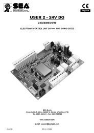
®Sistemi Elettronicidi Apertura Porte e CancelliInternational registered trademark n. 804888EnglishUSER 1 - <strong>24V</strong> <strong>DG</strong>DESCRIPTION OF THE COMPONENTSCN8F1CN7CN6CN5RD1RL1RL2PR1RD3CN4CNPDISPLAYCN3CNAUP DOWN OKCN2CN111 2 3 4 5 6 7 8 9 10 11 12 13CN1 = Input/Output connectorCN2 = Limit switch connectorCN3 = Jolly connectorCN4 = Master/slave connectorCN5 = Courtesy light output plugCN6 = Motors connectorCN7 = Batteries connectorCN8 = Power connectorCNA = Receiver connectorCNP = Programming connectorOK = Programming buttonDOWN = Programming buttonUP = Programming buttonRD1 =Motors piloting MosfetRD3 = Motors piloting MosfetR1 = Motors command relayR2 = Motors command relayPR1 = Rectifier jumperF1 = Fuse 6.3 AT2067411260REV 01 - 04/2012
®Sistemi Elettronicidi Apertura Porte e CancelliInternational registered trademark n. 804888EnglishGENERAL INFORMATIONThe information in this section of the manual are only for technicians or for qualified or authorizedinstallers.GENERAL CHARACTERISTICSUSER 1 - <strong>24V</strong> <strong>DG</strong>The USER 1 <strong>24V</strong> <strong>DG</strong> control unit has been designed to manage one low voltage motor with or without electronic limitswitches.It is of very small size and the big news is the LCD display on board that let you view and set in a simple and completeway all functions of the control unit.TECHNICAL SPECIFICATIONSControl unit power supplyAbsorption in stand byMax. motor chargeMax. accessories charge <strong>24V</strong>Max. Flash light chargeEnvironment temperatureProtection <strong>24V</strong>~Function logicOpening/closing timeTime of pauseThrustSlow downInput on connecting terminalOutput on connecting terminalBoard dimensionsSpecifications of optional batteriesSpecifications of external enclosureSpecial accessories24 V~30 mA200W<strong>24V</strong> 250mA<strong>24V</strong> (FL) 15W max.-20°C +50°CF1 (6.3 AT)Automatic/S.by Step1/S.By Step2/Sec./Dead man/2Butt.In selflearning in programming phaseAdjustable (from D sb to 4 min)Adjustable Opening and ClosingAdjustable Opening and ClosingBattery power supply / Total opening / Pedestrianopening adjustable / Balanceable edge /Stop / Limit switch opening and closing / Photocell 1and Photocell 2<strong>24V</strong>(FL) / Light (Max 100 mA) /Motor <strong>24V</strong> / <strong>24V</strong>aux156 x 100 mm<strong>24V</strong> Pb 1.2Ah min.305 x 225 x 125 mm - Ip55Battery charger card (cod.23101105),Programmer JOLLY (cod.23105276),Programmer OPEN (cod.23105290)The herein reported functions are available starting from revision 15.67411260REV 01 - 04/201221
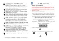
®Sistemi Elettronicidi Apertura Porte e CancelliInternational registered trademark n. 804888EnglishUSER 1 - <strong>24V</strong> <strong>DG</strong>WORKING TIMES SELF LEARNINGNOTE: When using a B200 motor or magnetic limit switches in general; make sure that the controlunit is set on magnetic limit switch before learning;SPECIAL MENU FC A AGNUUFOFig.11) Disconnect the power supply (Fig. 1), release the motor (Fig. 2) and put the leaves manually next to thestop in closing (Fig. 3-4).Reset the mechanical lock (Fig. 5)2) Connect the control board to the power supply (Fig.6).3) Select on the on-board display or JOLLY programmer, the type of motor that you are using as indicated inthe dispaly administration.4) Set the motor torque, the working speed, the deceleration and acceleration space and the slowdownspeed. If necessary also set the working logic and the other parameters.5) Select PROG on the display, press OK and than one of the UP or DOWN buttons. Now the gate willautomatically execute a closing, opening and reclosing cylce.Note: If the motor starts in opening, remove and re-put power supply, select on the display iN. T . Andthrough the UP and DOWN button put it on ON, or if you have the Jolly programmer, activate the motor andlimit switch exchange function. If the motor starts in closing and stops, remove the power supply andreverse the motor cables, then repeat starting from point 5.6)The self-learning is done.UATTENTION: This procedure is potentially dangerous and should only be performed by qualifiedpersonnel in safety conditions.The control unit is pre-set with the default settings, to start the control unit with the DEFAULT settings just keeppressed the UP and DOWN buttons at the same time power supplying the control unit the display shows themessage init.The settings of DEFAULT are: SLIDING MOTOR, AUTOMATIC LOGIC, SPEED 80%, PRE-FLASHING OFF, PAUSEenabled, OPENING AND CLOSING TORQUE 30%, SLOWDOWN SPEED 40%, SLOWDOWN LEARNING 80%,ACCELERATION 70%, DECELARATION 30%, ANTI-INTRUSION OFF, AUTOTEST OFF, PEDESTRIAN 30%,PHOTOCELL 1 CLOSING, PHOTOCEL 2 OPENING, MAX CYCLES 100000, WARNING LAMP NORMAL, TIMER OFF,BALANCED E<strong>DG</strong>E OFF, <strong>24V</strong>aux ALWAYS, START IN PAUSE OFF, COURTESY LIGHT 30 seconds.AONFig. 2 Fig. 5Fig.6Fig. 3 Fig. 7Fig. 8 Fig.42267411260REV 01 - 04/2012
®Sistemi Elettronicidi Apertura Porte e CancelliInternational registered trademark n. 804888EnglishSELECTION OF THE SETTINGSThe settings of the control unit are made through the UP, DOWN and OK buttons. The UP and DOWN buttons to scroll throughthe MENUS and SUBMENUS. By pressing OK you enter from MENU into SUBMENU and confirm the choice.Pressing the UP and DOWN buttons at the same time you access the SP MENU for special settings. Pressing the OK button for5 seconds, you enter the TEST MENU, where you can check the operating status of all inputs.Initial systemu.001UDOWNotSoftware VersionProgramming exampleUPOKUPUPUPSl dTRAIbarrDOWNOKDOWNOKDOWNOKUSER 1 - <strong>24V</strong> <strong>DG</strong>DISPLAYMENU <strong>SEA</strong> SETstrtMENU'strtstoppedoedgepko.1pko.2F a.iF .i67411260DescriptionStart testStop testMENU FUNCTION board USER1 <strong>24V</strong> <strong>DG</strong> INPUT TESTS(To access the Menu for input TESTS keep pressed OK for about 5 seconds)Pedestrian start testSafety edge testPhotocell 1 testPhotocell 2 testOpening limit switch testClosing limit switch testDescriptionThe contact must be N.O. If activating the related command on the displaythe item SET lights up, the input will be working.If SET is always on, check the wirings.IThe contact must be N.C. If activating the related command on the displaythe item SET lights up, the input will be working.If SET is always on, make sure that the contact is a N.C. oneThe contact must be N.O. If activating the related command on the displaythe item SET lights up, the input will be working.If SET is always on, check the wiringsThe contact must be N.C. If activating the related command on the displaythe item SET lights up, the input will be working.If SET is always on, make sure that the contact is a N.C. oneThe contact must be N.C. If activating the related command on the displaythe item SET lights up, the input will be working.If SET is always on, make sure that the contact is a N.C. OneThe contact must be N.C. If activating the related command on the displaythe item SET lights up, the input will be working.If SET is always on, make sure that the contact is a N.C. one.The contact must be N.C. If activating the related command on the displaythe item SET lights up, the input will be working. If SET is always on,make sure that the contact is a N.C. one or that the relatedlimit switch is not occupied.The contact must be N.C. If activating the related command on the displaythe item SET will light up, the input will be working. If SET is always on,make sur that the contact is a N.C. one or that the relatedlimit swith is not occupied.REV 01 - 04/201223
®Sistemi Elettronicidi Apertura Porte e CancelliInternational registered trademark n. 804888EnglishSELECTION OF THE SETTINGSUSER 1 - <strong>24V</strong> <strong>DG</strong>MENU functions table USER1 <strong>24V</strong> <strong>DG</strong>MENU'UotLogT.paTrsNUSPEEsl.dnsp.lrA lD l.oD l.P.opP. lpr.blLgbst.psUPrgSt.prendNN. TUDescriptionMotor typeWorking logicsTime of pauseTransmitterMotors speedSlowdown speedLearning speedAcceleration rampDeceleration ramp in openingDeceleration ramp in closingOpening torqueClosing torquePre-flashingFlash output adjustmentStart in pauseMotor and limit-switch inversionSelflearning timesTest startExit menuSETSl dUergergBarra toNp.p.1p.p.22p lNs uNO.prD sb1,2,3strtstpdU.Eststopdel.Del.s0 1000 1000 1000 1000 1000 1000 1000 100DisbDisb.05L.onLa pUspyalysbeepoffonoffonoffonoffonDescriptionSlidingVergErgHydraulic barrierAutomaticStep by step type 1Step by step type 2Two buttonsSafetyDead manDisabledSetting from 1s to 4min.StartPedestrian StartLight outputStopDelete TXDelete single transmitterMotors speedSlowdown speedLearning speedAcceleration rampDeceleration ramp in openingDeceleration ramp in closingOpening torqueClosing torquePre-flashing disabledPreflashing durationPre-flashing active only before closingFlashing lampControl lampAlways ONBuzzerIn pause start is not accepedIn pause start is acceptedSynchronized dx motorSynchronized sx motorTimes learning endTimes learning startSimulates a start commandSimulates a start commandDefaultSl dautoD sbstrtstpd8040807030303030Disbla poffoffoffoffSelect END and press OK to exit the menu.The menudeactivates automatically after 2 minutesUSet value2467411260REV 01 - 04/2012
UY lN. Yre.pst UrL.tiUPs.rdeNDUA.slFi. aUN®Sistemi Elettronicidi Apertura Porte e CancelliInternational registered trademark n. 804888EnglishSELECTION OF THE SETTINGSNumber of cycl. for maintenanceNumber of executed cyclesPosition recoveryTimer managementstrtD sb1,2,3D sbO. LoOp. LO.ope100 10e40 10e90 100D sbpk2pedD sb8.2L.irp.paLosopenstopParoffonUND sbslauUUAsteccU UUagn----67411260 REV 01 - 04/2012USER 1 - <strong>24V</strong> <strong>DG</strong>PRESS AT THE SAME TIME FOR 5 SECONDS TO ENTER THE SPECIAL MENUDOWN UPSpecial MENU functions table USER1 <strong>24V</strong> <strong>DG</strong>(You enter the Special Menu keeping pressed UP and DOWN at the same time for 5 seconds)MENU' SPL. ODescriptionCourtesy lightSETD sb1,2,3DescriptionCourtesy light disabledCourtesy light setting from 1s to 4min.Default30Set valuePed.oR. OtPedestrian openingLimit switch inversion0 100D sbAdjusts the space of pedestrian openingDisabled30D sbAdjusts the space of return after reading0 100 of the limit switchPause in pedestrian opening same as inp.ped Pedestrian Pausetotal openingstrtPedestrian pause disabledSetting from 1s to 4 min.all.r Anti-Intrusion alarmDisabledD sbOnly on limit switch in closingOn limit switches in closing and in openingOnly on limit switch in openingSetting from 100 to 100000i0e406D sbRegulates the recovery of the motor inertiaDisabledTimer function active on photocell 2Timer function active on pedestrian inputs.edg Safety edgeEdge is active but not protectedD sbEdge is active and protected by a 8k2 resistorPk.i Photocell 1 management Los Photocell active in closingLosopen Photocell active in opening and closingstop Photocell active before opening and in closingPar The photocell stops in closing and closes when releasedThe photocell gives a command to closeduring opening, pause and closingThe photocell charging the pausing timePk.2 Photocell 2 managementPhotocell active in closingPhotocell active in opening and closingPhotocell active even before openingPhotocell stops in closing and closes when releasedL.iThe photocell gives a command to closeduring opening, pause and closingrp.pa Photocell charging the pausing time24ua <strong>24V</strong>aux output management alys <strong>24V</strong>aux output always power suppliedOp. L<strong>24V</strong>aux output power supplied only duringopening and closingopen <strong>24V</strong>aux output power supplied only during openingLos <strong>24V</strong>aux output power supplied only during cloisngPa s <strong>24V</strong>aux output power supplied only during pausepk.te<strong>24V</strong>aux output for connection of photocellTX to autotestExcludes the operation of the photocell duringPh.of Photocell management exclusion 0 50% closing for the set percentage0T.opnT.cloAmperometric tolerancemanagement0 100%0 100%Adjust the amperometric tolerance inrelation to the detected stop in openingAdjusts the amperometric tolerance inrelation to the detected stop in closing00Courtesy light with timer managementMaster-slave managementLimit switch managementEnter passwordExit special menuopenalysAllows to keep the light switched offwhen the timer is active.offAllows to keep the courtesy light switched onwhen the timer is active.OFFD sbFor applications with two motors in masterslave,it allows to set the control unit as masterFor applications with two motors in masterslave,you can set the control unit as slave.Allows to choose if to use themechanical normally closed limit switch eccAllows to choose if using the magneticnormally opened limit switchAllows the entering of a password which blocs themodification of the control unit parameters (see page 30) ----Select END and press OK to exit the special menu.The special menu deactivates automatically after 2 minutes.25
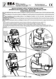
®Sistemi Elettronicidi Apertura Porte e CancelliInternational registered trademark n. 804888EnglishSTART - STOP - PEDESTRIAN START - ANTENNA -PHOTOCELLPhotocell 1 and Photocell 2 ConnectionsNote: If the photocells are not connected, put a jumper between the clamps (6,7,8).+ = <strong>24V</strong>(FL) COM = 0V PH1 = Photocell contact 1 PH2 = Photocell contact 2Note: For the autotest connect the TX to the <strong>24V</strong>aux clamp and activate the Autotest function.The standard setting of the photocell 1 is FOTO CLOSE and the one of the photocell 2 is FOTOOPEN. The photocell 2 can be set also as TIMER (see TIMER function).OPTIONS ON FOTO1 and FOTO2 adjustable on on- board display orwith JOLLY terminal.FOTO CLOSE activation ( Los): if occupied, reverses the movement in closing, duringpause it prevent the closing.Activation repeat pause (rP.PA): If occupied, during pause it recharges the timer ofpause. In closing it reverses the movement.FOTO OPEN activation (oPEn): If activated the photocell blocks the movement as longas it’s busy, when released the opening continues.FOTO PARK activation ( Par ): in opening it is not active; in pause are activated itcommands the closing when released, otherwise it’s not active; in closing it stops themovement as long as it is busy, when released the closing continues.FOTO STOP activation (STOP): When activated before the opening the photocellblocks the automation as long as it is busy, during the opening it will be ignored. Inclosing the intervention of the photocell causes the reopening.Activation PHOTO CLOSE IMMEDIATELY: The photocell stops the gate as long as itis occupied in both opening and closing, when released it gives a closing command(Closing one second after release of the photocell ).USER 1 - <strong>24V</strong> <strong>DG</strong>AntennaCommonStartStart ped.CN11 2 3 4 5 6 7 8StopCommonPhotocell 1Photocell 2Options <strong>24V</strong>aux can be set with on-board Display orwith Jolly device.Through the Jolly programmer it is possible to chose whenhaving tension on the <strong>24V</strong>aux output. The options are:always, only during opening, only during cycle, only beforeopening or only during pause.CN1RX1RX2PEDESTRIAN START (N.O.) The pedestrian start can beconnected between the clamps 2 and 4 of the CN1 terminal .This input allows a partial opening the opening space can be setthrough the on-board display or through the JOLLY device.Note1: The contact for partial opening is a N.O. Contact(Normally open).Note2:In 2 BUTTONS logic it is necessary to keep pressed theStart Ped. to re-close the automation.Note3: In dead man logic this button executes the re-closing ifyou keep it pressed.Note4: When closed during pause, the gate will reclose only afterthis input has been reopened.TIMER activation: This input can be transformed into TIMER(See TIMER).9 10 11 12 13<strong>24V</strong> (FL)CommonTX1TX2STOP (N.C.) The STOP is connected between the clamps 2 and 5 of the CN1 terminal .The pressure on this button immediately stops the motor in any condition/position. A start command is needed to re-start the movement.After a stop the motor always re-starts in closing.START (N.O.) The START is connected between the clamps 2 and 3 of the CN 1 terminal.An impulse given to this contact opens and closes the automation depending onthe selected logic it can be given by a key switch, a keypad,etc. To connect the other devices refer to the related instructions leaflets. (ie. loop detectors and proximity switches).Note1: In DEAD MAN logic it is necessary to keep pressed the Start for the opening of the automation.Note2: In 2 BUTTONS logic this button performs the opening.26TIMER67411260Can be activated through on-board display or through the Jolly programmer. In both cases it’s a N.O. contact which provoquesthe opening of the automation keeping it open until it is activated. When it’s released, the gate attends the set pausing timeand executes the reclosing. The TIMER command can be activated on the inputs FOTO2, START PEDESTRIAN.Note1: When activated on the pedestrian entry, the pedestrian will be disabled also on the radio transmitter.Note2: In case of intervention of a security device during the timer (Stop, Ammeter, Edge), to restore the movement it will benecessary to give a start impulse.Note3: In case of no power supply with open gate and active Timer the control unit will restore its use, otherwise if duringrestore of the power supply the TIMER is not activated it will be necessary to give a start impulse for the reclosing.REV 01 - 04/2012
®Sistemi Elettronicidi Apertura Porte e CancelliInternational registered trademark n. 804888EnglishLIMIT SWITCH AND SENSOR BARRIERSSensor barriersThis control unit comes with a detection device of motor current absorbtion which allows toreveal possible obstacles during the opening and the closing of the gate. When this deviceintervenes in opening it causes the inversion of the movement for around a second, if itintervenes in closing it causes the total reopening.Note1: The ammeter sensitivity is adjustable both in opening and in closing through theon-board display or through the JOLLY terminal. With high torque the gate reverses after5 seconds.Attention: In case of obstacle, if the automatic reclosing is on, the gate will attempt toclose for 3 times, whereupon a start signal will be necessary to re-establish themovment.USER 1 - <strong>24V</strong> <strong>DG</strong>Limit switchThe limit switch can be connected through the special LIMIT SWITCH connector onthe control unit. The control unit can administrate mechanical, inductive and magneticlimit switches. Only on some special applications il will not be necessary to connectthe limit switches. The control unit will automatically realize if limit switches arepresent or not.1) Through the on-board display or through the JOLLY programmer it is possible toactivate the ani-intrusion function. This function is lied to the presence of at least onelimit switch which, when free, forces the motor to re-close.Note: if during programming phase the motor and limit switch times should notbe in phase between them, the gate will start in closing, it stops and will notcomplete the selflearning of the times, at this point it will be necessary toswitch off the tension and to invert the cables of the motor. The first movementin selflearning must always be executed in closing.LimitSwitchCN2ATTENTION: When using <strong>SEA</strong> magnetic limit switches, make sure that the limitswitch is set on AGN.USECURITY E<strong>DG</strong>E AND WARNING LAMPSECURITY E<strong>DG</strong>EBetween clamps 9 and 11 of CN 1 it is possible to connect an active safety edge on the terminal M8. If thisdevice is pressed it opens the contact causing a partial inversion of the movement both in opening and inclosing. If not used you must put a jumper between the contacts GND and 9 of CN1.Note1: contact N.C.Note2: Through the on-board display or the Jolly programmer it is possible to activate the balanced edge8K2, in this case the edge contact is controled by a special resistance value revealing the eventualinvoluntary short- circuit of the device. In case of imbalance of the device a special alarm will show on theon-board dispaly or on the JOLLY programmer.Security edgeEdge9 10 11 12 13<strong>24V</strong>AuxCN1Common<strong>24V</strong> (FL)FL(-)Flashing Lamp <strong>24V</strong> 15W (Warning lamp )The flashing lamp can be connected between the clamps <strong>24V</strong> (FL) and FL (-) of CN 1.The warning lamp advises that the automatic gate is moving with 1 flash/second in opening and 2 flashes / second in closing. During pause itremains switched on. Through the warning lamp it is also possible to identify alarms lied to the STOP, PHOTOCELL 1, PHOTOCELL 2 andE<strong>DG</strong>E devices. Through the display or the JOLLY programmer it is possible to activate the pre-flashing function and/or to modify the function ofthe warning lamp choosing between fix flashing, control lamp or Buzzer.ALARMS INDICATIONSThe flashing sequence is signalled at every opening and closing of the automation on the warning lamp. The warning lamp willsend a flashing every second in opening and two flashings in closing, while it will remain turned on fixed in pause.Flashings Number234Kind of alarmPhotocell in closingPhotocell in openingSafety edgeFlashings Number679Kind of alarmCollision on obstacleReached maximum cyclesMotor failure5 Stop4 speeds Limit switch error67411260REV 01 - 04/201227
®Sistemi Elettronicidi Apertura Porte e CancelliInternational registered trademark n. 804888EnglishMOTOR POWER SUPPLYUSER 1 - <strong>24V</strong> <strong>DG</strong>115V~o230V~TRANSFORMERGNPPOWER (CN8)3,6 A blow fuse on 230V ~ power supply6,3A blow fuse on 115V ~ power supplyCN8CN6G N PP N GM+ M-12MOTOR (CN6)Power inputInput for the connection of the electricpower.P = PHASE - LIVEN = NEUTRALG = GROUNDNOTICE: for theconnection to theelectric power see thelaw in force.P N GEXTERNAL RECEIVERCN11 2 3 4 5 6 7 8 9 10 11 12 13Example: Connection of aradio receiverFor the connection of thereceiver refer to the relativeinstructions manual.+-StartStart ped.CommonCommon<strong>24V</strong> (FL)2867411260REV 01 - 04/2012
®Sistemi Elettronicidi Apertura Porte e CancelliInternational registered trademark n. 804888EnglishUSER 1 - <strong>24V</strong> <strong>DG</strong>RADIO TRANSMITTER SELF LEARNINGWITH RECEIVER ON BOARD OF CONTROL UNIT!WARNING: Make the radio transmitters programming before you connect the antenna and insert the receiver into thespecial CMR connector (if available) with turned off control unit. (The control unit automatically recognizes if the receiver is a RF, RFRoll or RF Roll Plus module).With RF Roll or RF Roll Plus module it will be possible to use only Coccinella Roll or Coccinella Roll Plus radio transmitters.With RF UNI module it will be possible to use both Coccinella Roll Plus transmitters and radio transmitters with fixed code. The firstmemorized radio transmitter will determine the type of the remaining radio transmitters.Select through the display TrS and press OK, now select with the UP and DOWN buttons, the command to which you want to associate thebutton (it is possible to associate max. 2 commands) and press OK to confirm the choice, now press the button of the radio transmitter whichyou want to associate. If the storage is successful, the display will show E .If the receiver is a Rolling Code, press twice the button of the radio transmitter that you want to program to memorize the first TX.In the TrS MENU it is possible to select Strt (to associate a Start command), StPd (Pedestrian Start ), .Est (To activate the LIGHT contact),StoP (To associate the STOP command to the TX), dEL (To delete all TX).UUNotes:- Enter radio transmitters learning only when the working cycle stops and the gate is closed.- If the radio transmitters are Rolling Code it’s possible to memorize up to 800 codes (buttons).- If the radio transmitters are with fixed code it will be possible to memorize up to max. 30 codes (buttons).- You can store max. 2 of the available 4 functions. If the control unit receives a code which was already associated to another function it will beupdated with the new function.UUUDELETE TRANSMITTERS FROM THE RECEIVERWith modules different from RF UNI, it will be possible to delete only the entire memory of the receiver.Proceed as follows: select from the menu TrS DEL and hold the OK button until the display shows the message DONE.With the RF UNI module, it will be possible to also delete the single button of the transmitter.It can be done in two ways:1) If you have the transmitter, or if you are using transmitters with fixed code, the cancellation can be executed by simply retransmitting thecode. Ex. Button 1 of the transmitter memorized as START; access the menu TrS press OK, select STRT, press OK.Send a STRT command from the transmitter and on the display will show DEL.At this point the single button results deleted.2) If you do not have a transmitter, or you are using a Roll Plus transmitter, you can delete the transmitter selecting the serial number of thetransmitter to be deleted.Procede as follows: Access the menu TrS , press OK, select DELS, press OK, choose the memory location to be deleted through the UP andDOWN buttons, press OK, check on the display if the serial number of the transmitter to be deleted is the right one, press OK, on the displayshows SURE, if the transmitter to be deleted is the right one press OK, otherwise press the DOWN button to return to the menu TrS .UUNote: When using Roll Plus transmitters, it is recommended to record on a table similar to the below example, the serial number associatedingit to the memory location where it was stored.UUTABLEEXAMPLE67411260MemorylocationTransmitterbutton012345678910111213141516171819201 2 3 4REV 01 - 04/2012Serial numberCustomer29
®Sistemi Elettronicidi Apertura Porte e CancelliInternational registered trademark n. 804888EnglishFUNCTION LOGICUSER 1 - <strong>24V</strong> <strong>DG</strong>AUTOMATIC LOGICA start impulse opens the gate. A second impluse during the opening will not be accepted.A start impulse during closing reverses the movement.NOTE 1: To have the automatic closing it is necessary to set a pause time, otherwise all the logic will be semi-automatic.NOTE2: It is possible to choose, whether to accept or not, the start in pause, selecting in the MENU the item ST.PS and choosing ONor OFF. By default, the parameter is OFF.SECURITY LOGICA start impulse opens the gate. A second impulse during opening reverses the movement.A start impulse during closing reverses the movement.NOTE 1: To have the automatic closing it is necessary to set a pause time, otherwise all the logic will be semi-automatic.NOTE2: It is possible to choose, whether to accept or not, the start in pause, selecting in the MENU the item ST.PS and choosing ONor OFF. By default, the parameter is OFF.STEP BY STEP TYPE 1 LOGICThe start impulse follows the OPEN-STOP-CLOSE-STOP-OPEN logic.NOTE 1: To have the automatic closing it is necessary to set a pause time, otherwise all the logic will be semi-automatic.NOTE2: It is possible to choose, whether to accept or not, the start in pause, selecting in the MENU the item ST.PS and choosing ONor OFF. By default, the parameter is OFF.STEP BY STEP TYPE 2 LOGICThe start impulse follows the OPEN-STOP-CLOSE -OPEN logic.NOTE 1: To have the automatic closing it is necessary to set a pause time, otherwise all the logic will be semi-automatic.NOTE2: It is possible to choose, whether to accept or not, the start in pause, selecting in the MENU the item ST.PS and choosing ONor OFF. By default, the parameter is OFF.DEAD MAN LOGICThe gate opens as long as the START button of opening is pressed; releasing it the gate stops. The gate closes as long as the button connectedto the PEDESTRIAN START is pressed; releasing it the gate stops. To execute complete opening and/or closing cycles the relatedpushbuttons must be constantly pressed.2 PUSHBUTTONS LOGICOne start opens, one pedestrian start closes. In opening the closing will not be accepted. In closing a start command reopens, a pedestrian startcommand (closes) will be ignored.PASSWORD ENTERING MANAGEMENTWith a new control unit all menus can be displayed and set and the password will be disabled.Selecting one of the Menus and keeping UP and DOWN pressed at the same time for 5 seconds, you will access the SP Menu containing thePS.rd. Submenu.Pressing OK in the PS.rd. Menu, you will proceed with the entering of the numeric code of the 4-digit PASSWORD.Use UP and DOWN to increase or decrease the number, press OK to confirm it and you will pass automatically to the entering of the nextnumber. Pressing OK after the last entered number the word SURE appears, confirm the activation of the PASSWORD and the message DONEappears, pressing UP or DOWN instead you can cancel the operation and NULL will appear on the display.Once entered the PASSWORD, it will be definitively activated, once the display switch off timeout has expired, or by turning off and on again thecontrol unit. Once the PASSWORD has been activated, the menus of the display can be only displayed but not set. To unlock them you mustenter the correct PASSWORD in the PS.rd menu, if the password is wrong the message ERR will appear.At this point, if the password has been entered correctly, the menus will be unlocked and it will be possible to change the parameters of thecontrol unit again.If the control unit has been unlocked through PS.rd. Menu, it is possible to enter a new and different password, using the same entering processas for the first one; at this point, the old password will no longer be valid.If the password has been forgotten, the only way to unlock the control unit is to contact the <strong>SEA</strong> technical assistance, which will assess whetherto provide the procedure to unlock the control unit or not.Note: The password cannot be set through the Jolly terminal.3067411260REV 01 - 04/2012
®Sistemi Elettronicidi Apertura Porte e CancelliInternational registered trademark n. 804888EnglishMASTER-SLAVE FUNCTIONTo set an installation with two motors in MASTER-SLAVE function it is recommended to do as follows:USER 1 - <strong>24V</strong> <strong>DG</strong>1) Set the two motors as if they were two independent installations, make sure that the individual motor works properly and thatthe limit switches (when present) are read properly.2) Once sure of the correct functioning connect the control unit MASTER to the control unit SLAVE through the special clamp(Code <strong>SEA</strong> 23001220).3) Now set the control unit, which has to manage the commands and motor 1 (photocell, keyswitch, STOP, safety edge etc.) asMASTER and the other one which will move motor 2 as SLAVE.4) Follow up the selflearning of the times of the MASTER control unit.Note 1: The master and slave settings on the control unit are present in the special menu selecting ASLNote 2: All these operations can also be managed through the JOLLY programmer).Note 3: On the SLAVE it is possible to set the following functions only: torque, speed, motor type, slowdown speed, acceleration,deceleration, position recovery, <strong>24V</strong> aux and motor inversion. All other parameters will be set only by the MASTER control unit.Note: respect the polarity of the cables.UM1M1SIGACOMSIGBSIGACOMSIGBCN4It is recommended to use a two twisted pairs shielded cable2with less than 0.5 mm section.Insert on CN4of the Master control unitInsert on CN4of the Slave control unitCONNECTION OF BATTERIES TO BATTERY CHARGER CARDCod.23101110CN1= charge ~ 200mA= charge ~ 360mA= charge ~ 800mASolar Panel+GND GND PSOL BAT 28V(BAT)+S-28V Battery chargerPositive batteryNegative battery chargerGND- +12V- +12VBattery current (mA)800360200Battery (Ah)12 or 167267411260BatteriesREV 01 - 04/2012Insert two 12V batteries connected in series.31
®Sistemi Elettronicidi Apertura Porte e CancelliInternational registered trademark n. 804888EnglishUSER 1 - <strong>24V</strong> <strong>DG</strong>PROGRAMMER JOLLY PARAMETERS ADJUSTMENTThe JOLLY programmer allows to keep under control and to change all parameters of the control unit without need to use thebuttons of the control unit. Compared to the on-board display, the programmer allows to view the programming instructions inthe user's language and in a non-encrypted way. In addition to the JOLLY programmer, the user can work comfortably standingup without looking at the control unit.Screen 1Language: ItalianScreen 2CycleEncoderTime of pauseWith buttons + and - it is possible to modify the languageAutomat./Secur./Step by step1/Step by step2/Dead man/2 boutonson/off (function with encoder, not implemented)[0÷120]s (time of pause in seconds)The arrow shows that theparameter is modifiable with thebuttons + and -Shows the working logicadjusted on board of the controlunit.Screen 3LearningModalityCicli exec.Mem. freeon alignment/off (signalling of the execution ofthe learning)Master/Slave32[0÷2 ] (number of executed cycles)[0÷100]% (percentage of availablememory for the learning of remote controls)Note: The alignment appears only ifphotocells are present on the BUS.Screen 4Motor (Sliding) (Barrier) (Joint)Speed[30÷100 ] adjusts the motors’ speedSl. speed[30÷100 ] adjusts the slow down speedLear. Speed. [30÷100 ] adjusts the learning speedScreen 5Accelerat.Decelerat.Pedestrian op.[0÷100]% (inclination of the ramp of acceleration)[0÷100]% (inclination of the ramp of acceleration)[30,50,100]% (percentage pedestrian opening)Indicates the type of motor setIt allows to regulate the duration ofthe acceleration of the motors onthe start If on 100% the gate willimmediately depart at the max.adjusted speedIt allows to regulate the duration ofthe deceleration of the motor at theend of opening and closing. If on 0%the gate won't effect the phase ofdeceleration.Screen 6Torque op. M1Torque clo. M1Screen 7Anti-intrusionPre- flashingAutotest photo.Max cycle[10÷100]% (max. current of the motors)[10÷100]% (max. current of the motors)on/off (in ON it implicates the presence of a contact N.C.On the limit switch that, if freed, forces the motors in closing)on/off (activation of the pre-flashing)on/off (activates autotest photocell)0÷100000 (indicates the number of cycles after which it isnecessary to follow up the maintenance)Allows to regulate and to visualizethe sensitivity of the anti-sqeezingfor single opening direction. Withvalue 100% the gate in presence ofobstacle will reverse the movementafter 5 seconds.3267411260REV 01 - 04/2012
®Sistemi Elettronicidi Apertura Porte e CancelliInternational registered trademark n. 804888EnglishPROGRAMMER JOLLY PARAMETERS ADJUSTMENTNOTE: For the respect of the valid European ruels on the safety of the electric gates, it is recommended to not adjust theparameters torque on the value 100%.Screen 8Warning lampPhotoReverse strokeBalanc. edgeNormal/Control/ContinuousClosing/opening/stop/park/close immediatelyon/off (Disabled)Off ( In ON it allows to connect an active edgebalancing it with a 8k2 resitance).USER 1 - <strong>24V</strong> <strong>DG</strong>Normal:1 Flash/s in opening2 Flash/s in closingOn in pauseControl lamp: the alarm signalsremain until they are eliminatedContinuous: flashes always alsowhen gate is not in movementScreen 9Photo/TimerPed/TimerClos. PhotoPos. Recovery .Screen 10<strong>24V</strong> auxAutom. clos.Start on pauseMot. rev.Screen 11Start commandLim. Sw inv.Courtesy t.ON/OFF On ON the PHOTO entry becomes TIMERON/OFF On ON the PED entry becomes TIMERON/OFF On ON if the photocell is occupied the gaterecloses interrupting the pause[0÷100]% (recovery rate of the position)During cycle/in opening/in closing/in Pause/AlwaysON/OFF If on ON at the end of the set pausethe gate re-closes automaticallyON/OFF If on ON with autom. Clos. on ON a startimpulse provoques the immediate re-closing of the autom.ON/OFF Allows to exchange contemporarily the limit switchand the motor rotation direction without disconnecting thewires[ON/OFF] (equivalent to a test start)[0÷100]% (admin. The space of lim. sw. relase afterclosing)[0÷4 min.] (Adjusts the courtesy light lighting up)For the functions Fotoopen,Fotostop, Fotopark, see page 26.Allows to optimize the point ofslowdown beginning in case ofinversion of the motion and infunction of the weight of the gateAllows to decide when havingpower supplied the exit <strong>24V</strong> Aux.Note: After this operation it isnecessary to switch off the powersupply of the motors and to repeatthe selflearning of the times. If themotor is not syncronized with thelimit switch, during selflearning theautomation stops on the first limitswitch it recognizes withoutcompleting the selflearning of thetimes. In that case it will benecessary to switch off the powersupply again, to manuallyexchange the wires of the motorand to repeat the selflearning.Screen 16List of eventsN°10N°9N°8Shows the last 10 events on the control unitDiagnostic 10 last events67411260REV 01 - 04/201233
®Sistemi Elettronicidi Apertura Porte e CancelliInternational registered trademark n. 804888AdvisesMake sure all Safeties are turned ONAll N.C. contacts must have jumpersEnglishTROUBLE SHOOTINGProblem Found Possibile Cause SolutionsMotor doesn’t respond to anySTART impulsea.) Jumper missing on one of the N.C.Contactsb.) Burnt fuseUSER 1 - <strong>24V</strong> <strong>DG</strong>a.) Check the connections or the jumpers on theconnections of the safety edge, of the stop andof the photocellb.) Replace the burned fuse on the control unitGate doesn’t move while themotor is runningGate doesn’t reach the completeOpen / Closed positionThe gate opens but doesn’tcloseThe gate doesn’t closeautomaticallya.) The motor is in the released positionb.) There is an obstaclea.) Wrong setting of the limit switchesb.) Error on programmingc.) Gate is stopped by an obstacled.) Torque or speed too lowa.) The contacts of the photocells are open.b.) The stop contact is openc.) The edge contact is opend.) Ammeter alarma.) Pause time set to highb.) Control unit in semi-autom. logica.) Re-lock the motorb.) Remove obstaclea.) Set limit switchesb.) Repeat programmingc.) Remove obstacled.) Increase torque parametera.) b.) c.) Check the jumpers or the signalsindicated on the warning lampd.) Check if the ammeter alarm has intervened andeventually increase the torque parameter.a.) Adjust pause timeb.) Set the pause parameter on a different valuefrom the D sbPage for both instaler and userMAINTENANCEConsidering the number of working cycles and the kind of gate, if the gate has changed the clutches and doesn’t work it’s necessary toperiodically proceed, with the learning times reprogramming on the electronic control unit.Periodically clean the optical systems of the photocells.REPLACEMENTSAny request for spare parts must be sent to:<strong>SEA</strong> s.r.l. - Zona Ind.le, 64020 S.ATTO - Teramo - ItaliaSAFETY AND ENVIRONMENTAL COMPATIBILITYDisposal of the packaging materials of products and/or circuits should take place in an approved disposal facility.REGULAR PRODUCT DISPOSAL (electric and electronic waste)(It’s applicable in EU countries and in those ones provided with a differential waste collection)The brand that you find on the product or on documentation signals that the product must not be disposed off together with other domesticwaste at the end of life cycle. In order to avoid any possible environmental or health damage caused by irregular waste disposal, werecommand to separate this product from other forms of waste and to recycle it in a responsible way in order to provide the sustainable re-use ofmaterial resources. Domestic users are invited to contact the retailer where the product has been purchased or the local office in charge of allthe information related to differential watse collection and recycling of this kind of product.STORINGWAREHOUSING TEMPERATUREST min T Max Dampness min Dampness Max- 20°C + 65°C5% Not condensing 90% Not condensingMaterials handling must be made with appropriate vehicles..WARRANTY LIMITSFor the guarantee see the sales conditions on the official <strong>SEA</strong> price list.<strong>SEA</strong> reserves the right to make any required modification or change to the products and/or to this manual without any advanced noticeobligation.3467411260REV 01 - 04/2012