Verg Instructions - SEA (UK)
Verg Instructions - SEA (UK)
Verg Instructions - SEA (UK)

You also want an ePaper? Increase the reach of your titles
YUMPU automatically turns print PDFs into web optimized ePapers that Google loves.
.4) Fitting the ‘balance pin - P’ into the Balance Arm.Insert the bearing (A) into either balance hole 1 or 2 of the balance bar ifthe beam is ‘closing to the right’. Or hole 3 or 4 if the beam is closing to theleft. The choice of which hole to use depends on the length and type ofbeam that requires balancing – see tables below.Carefully tap the bearing A into the chosen ‘balance beam’ hole using aplastic mallet and pin P as a drift as shown in the drawing (right).The bearing should be flush with the face side of the beam and protrude alittle at the rear to allow for the large washer to fit over the protrudingbearing. Grease all moving parts during assembly.Fit the ‘travel stop’ bolts & nuts in readiness for final adjusted later (fig 6).Travel StopBolts & NutsBalanceHoleOperatingTime secsBalanceHoleOperatingTime secsStrictly adhere to the ‘Operating Times’ shown above for reasons of Safety & Operational efficiencyThe Spring and Beam Fixing Bracket are supplied with the Beam.Fitting the SpringHook the Spring onto lower Anchor Bracket ‘S’.Insert the threaded rod into bracket ‘B’ and screw on the spring retainingnuts ‘D’. They only require to be hand tight at this stage. They willrequire adjusting & tightening after balancing the Beam – See the nextsection.
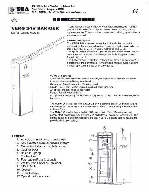
9) Electrical LayoutFig. 11 is showing an example of the various types of control equipment that can be used to control a <strong>Verg</strong> 24 TrafficBarrier.N.B. The figures shown beside each cable indicate the number of core and the cable cross-section – This informationis given for guidance purposes only, site conditions may dictate that different cabling to that shown is required.Legend1 – Electronic Control Unit2 - Photocell Transmitter3 – Photocell Receiver4 – Key Switch5 – Radio Receiver6 – Flashing Warning Light7 – Push button8 – 30mA RCD/Fuse & IsolatingSwitchRoutine Maintenance.The following schedule should be carried out at:-12 month intervals for <strong>Verg</strong> 24 Barriers that operate up to 50 times per day.3 month intervals for intensively used <strong>Verg</strong> - 50 plus operations per day.ProcedureTime PeriodCheck the Emergency Release device is operating correctlyCheck the Balance Spring is correctly adjustedLubricate the ‘Balance’ Bearing and Pin.Check all fixing nuts & boltsTest the RCD operation, cables and connectionsTest the batteries are functioning correctly (where applicable)Test and adjust the setting of the electronic anti-crush motor torque sensor3 or 12months3 or 12months3 or 12months3 or 12months3 or 12months3 or 12months3 or 12monthsN.B. All of the above routine maintenance checks and tests must be carried out byqualified, authorised personnel only.
IMPORTANT NOTICEAll electrical works must be carried by fully qualified personnel and in accordance with thecurrent regulations. The operation of this device must conform to current regulations.The <strong>Verg</strong> 24 Barrier has been designed and manufactured to be used exclusively as a Traffic BarrierPlease responsibly recycle all packaging supplied with this productLong Term Decommissioning and MaintenanceThe decommissioning and maintenance of this product must be carried out by qualified authorised personnel.The Manufacturer or Supplier shall not be held responsible for any injury or damage caused by inappropriate orcareless use of this product.