UNAC GUIDE No. 1 FOR THE MOTORISATION OF ... - Aprimatic
UNAC GUIDE No. 1 FOR THE MOTORISATION OF ... - Aprimatic
UNAC GUIDE No. 1 FOR THE MOTORISATION OF ... - Aprimatic

You also want an ePaper? Increase the reach of your titles
YUMPU automatically turns print PDFs into web optimized ePapers that Google loves.
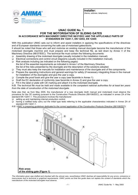
Installer:(Name, address, telephone)<strong>UNAC</strong> <strong>GUIDE</strong> <strong>No</strong>. 1<strong>FOR</strong> <strong>THE</strong> <strong>MOTORISATION</strong> <strong>OF</strong> SLIDING GATESIN ACCORDANCE WITH MACHINERY DIRECTIVE 98/37/EEC AND <strong>THE</strong> APPLICABLE PARTS <strong>OF</strong>STANDARDS EN 13241-1, EN 12453, EN 12445With this publication <strong>UNAC</strong> sets out to inform and assist installers in applying the specifications of the directivesand of European standards concerning the safe use of motorised gates/doors.It should be noted that those who sell and motorise an existing manual door/gate become the manufacturer of themotorised door/gate machine and must prepare and keep the technical file, as laid down by Annex V of theMachinery Directive (98/37/EEC). The technical file must contain the following documents: Assembly drawing of the motorised door/gate (usually included in the installation manual).Electrical connections and control circuit diagrams (usually included in the installation manual).Risk analysis including (as indicated on the following pages):the list of the essential requirements as indicated in Annex I of the Machinery Directive;the list of the risks presented by the door/gate and the description of the solutions adopted.They must also keep the manuals for installation and maintenance of the door/gate and of the components.Prepare the operating instructions and general warnings for safety (if necessary integrating those in the manualfor installation of the door/gate) and give the user a copy. Compile the proof book and give the user a copy (see facsimile in Annex 1). Draft the EC declaration of conformity (see facsimile in Annex 2) and give the user a copy. Fill in the label or plate with CE marking and attach it to the motorised door/gate.N.B. The technical file must be held and made available to the competent national authorities for at least ten yearsfrom the date of construction of the motorised door/gate.<strong>No</strong>te also that, as from May 2005, the manufacturer of a new door/gate (both manual and motorised) must observe theprocedure for the CE marking pursuant to the Construction Products Directive (89/106/EEC), as indicated in annex ZA of thestandard EN 13241-1. This procedure involves the manufacturer: setting up and maintaining internal production control; having a notified body carry out the initial type tests referring to the applicable characteristics indicated in Annex ZA ofstandard EN 13241-1.N.B. <strong>UNAC</strong> is preparing guidelines dedicated to the correct application of the Construction Products Directive (89/106/EEC).Risk areasof the sliding gate (Figure 1)The information given was drafted and checked with the utmost care, nevertheless <strong>UNAC</strong> declines all responsibility for any errors, omissions orinaccuracies due to technical or graphical requirements. <strong>UNAC</strong> points out that this guide does not replace the content of standards which themanufacturer of the motorised door/gate must observe.- 1 - <strong>UNAC</strong> Guide <strong>No</strong>. 1 - May 2005
KEY TO <strong>THE</strong> MECHANICAL RISKS CAUSED BY MOVEMENT <strong>OF</strong> <strong>THE</strong> GATEPursuant to the Machinery Directive: “Danger zones” refer to any zone within and/oraround machinery in which an exposed person issubject to a risk to his or her health and safety. “Exposed person” refers to any person wholly orpartially in a danger zone.ImpactCrushingShearingDraggingCuttingHookingMINIMUM LEVEL <strong>OF</strong> PROTECTION <strong>OF</strong> <strong>THE</strong> MAIN EDGEType of useType of actuationInformed usersInformed usersUninformed userscontrols(private area)(public area)Hold-to-run control Pushbutton control Pushbutton control with key Hold-to-run control notpossibleImpulse control with doorvisibleLimitation of forces, orpresence sensing devicesLimitation of forces, orpresence sensing devicesLimitation of forces andphotocells, or presenceImpulse control with doornot visibleAutomatic control (e.g.timed closure control)Limitation of forces, orpresence sensing devicesLimitation of forces andphotocells, or presencesensing devicesLimitation of forces andphotocells, or presencesensing devicesLimitation of forces andphotocells, or presencesensing devicessensing devicesLimitation of forces andphotocells, or presencesensing devicesLimitation or forces andphotocells, or presencesensing devicesANALYSIS <strong>OF</strong> <strong>THE</strong> RISKS AND CHOICE <strong>OF</strong> SOLUTIONSIN ACCORDANCE WITH <strong>THE</strong> MACHINERY DIRECTIVE 98/37/EEC AND <strong>THE</strong> STANDARDS EN 13241-1, EN12453, EN 12445The risks listed below follow the sequence of the installation process. These risks are those which are commonlypresent in motorised doors/gates systems. According to the various situations, consideration therefore has to bemade of any possible additional risks and exclude those which are not applicable. The solutions to be adopted arethose indicated by the standards mentioned above; in the case of risks not dealt with, the safety integrationprinciples indicated by the Machinery Directive (Annex 1 – 1.1.2) have to be applied.MDANN. 11.3.11.3.21.5.15Type of risksMechanical, structural andwear risks.[1] Loss of stability andbreak-up.[2] Tripping.Evaluation criteria and solutions to be adopted(Tick the box corresponding to the solution adopted) Check the solidity of the structure installed (jambs, hinges and leaves) inrelation to the forces generated by the motor.Attach the motor stably using adequate materials.If available, check the content of the EC declaration of conformity of themanual gate. If necessary, carry out the structural calculation and attach it to theTechnical File. Check that the travel of the leaves is limited (during opening and closure)by mechanical stops of adequate strength.Check that the leaves cannot, under any circumstance, exit their slide guidesand fall. Check that any thresholds higher than 5 mm are visible, indicated orshaped.- 2 - <strong>UNAC</strong> Guide <strong>No</strong>. 1 - May 2005
MDAnn. 11.3.71.3.81.4Type of risksEvaluation criteria and solutions to be adopted(Tick the box corresponding to the solution adopted)Mechanical risks caused by the movement of the gate (see references in Figure 1). CAUTION – If the door/gate is used solely with hold-to-run controls (and meets the requirements of thestandard EN 12453), the danger points listed below do not have to be protected. CAUTION – If protective devices are installed (in accordance with the standard EN 12978) which prevent inall cases contact between the moving leaf and persons (for example photoelectric barriers, presence sensingdevices), it is not necessary to measure the operating forces.[3] Impact and crushing on the main closingedge (Figure 1, risk A). Measure the closure forces (by means of thespecial instrument required by the standard EN12445) as illustrated.Check that the values measured by the instrumentare below those indicated in the graph.Carry out the measurements in the following points:L = 50, 300 and 500 mm;H = 50 mm,at mid-height of the leaf andat the height of the leaf minus 300 mm (max2500).ProtectiveDeviceN.B. The measurement should be repeated threetimes in each point and the average valueconsidered.The graph indicates the maximum values of thedynamic, static and residual operating forces inrelation to the various positions of the leaf.ForceN. B. With reference to the measurement points withL = 50, 300 and 500 mm, the maximum dynamicforce value permitted is 400 N.Dynamic forceIMPACT If the values of the forces are higher, install aprotective device in accordance with the standardEN 12978 (for example a sensitive edge) and repeatthe measurement.Static forceCRUSHINGN. B. The dynamic force can be reduced, forexample, by reducing the speed of the leaf or usinga sensitive edge with high elastic deformation.time[4] Impact on the main closing edge (Figure 1,risk A). To reduce the risk of impact between the slidingleaf and persons (or vehicles), a pair of photocellsmust be installed (preferably on the outside) asillustrated (recommended height 500 mm). In the cases where the thickness of the leaf isgreater than 150 mm, or when the impact risk is high(such as for example the presence of unattendedchildren), a second pair of photocells should beinstalled (on the inside), as illustrated (recommendedheight 500 mm).N.B. The test specimen for presence sensing is aparallelepiped (700 x 300 x 200 mm) having 3 faceswith a light and reflective surface and 3 faces with adark and opaque surface.Protective deviceSpecimen forpresencesensingSpecimen forpresencesensing- 3 - <strong>UNAC</strong> Guide <strong>No</strong>. 1 - May 2005
MDAnn. 1Type of risks consideredEvaluation criteria and solutions to be adopted(Tick the box corresponding to the solution adopted)[5] Impact and crushing in the area of opening (Figure 1, risk B). Observe the safety distances illustrated, in the two different cases.or: Measure the forces of opening (by means of thespecial instrument required by the standard EN12445) as illustrated.Check that the values measured by the instrumentare less than those indicated in the graph.Carry out the measurements in the followingpoints:L = 50, 300 and 500 mm;H = 50 mm,at mid-height of the leaf andat the height of the leaf minus 300 mm (max2500).N.B. The measurement should be repeated threetimes in each point and the average valueconsidered. If the values of the forces are higher, install aprotective device in accordance with the standardEN 12978 (for example a sensitive edge) andrepeat the measurement.Protective deviceProtective device[6] Shearing between the sliding leaf and fixedpart during the movement of opening andclosure (Figure 1, risk C). The leaf of the sliding gate and the enclosuremust be free from gaps, or the gaps must becovered with a net whose mesh sizes depend onthe distance of the leaf from the enclosure.Dimensions of themeshes of the netDistance between theleaf and the enclosure< 18.5 120from > 18.5 to < 29 300from > 29 to < 44 500> 44 850Protective device Or a protective device should be installed inaccordance with the standard EN 12978 (forexample a sensitive edge) as illustrated. Eliminate or protect any sharp edges, handles,projecting parts etc. (for example by means ofcovers or strips in rubber).- 4 - <strong>UNAC</strong> Guide <strong>No</strong>. 1 - May 2005
MDAnn. 11.3.71.3.81.4Type of risksMechanical risks due tomovement of the leaf.[7] Dragging of the handsin point (Figure 1, risk D).[8] Dragging of the feet onthe lower edge (Figure 1,risk E).[9] Dragging of the handson the drive unit (Figure1, risk F).Evaluation criteria and solutions to be adopted(Tick the box corresponding to the solution adopted) Check that there is a clearance ≤ 8 mm.or: attach guards that prevent fingers from being inserted (for example a rubberstrip). The clearance between the gate and ground must prevent the risk ofdragging of the feet. Adequately protect the point of dragging between the pinion and the rackduring movement of the leaf.1.5.11.5.21.5.101.5.11Electrical andelectromagneticcompatibility risks[10] Direct and indirectcontacts.Dispersion of electricalenergy.[11] Risks relating toelectromagneticcompatibility. Use CE-marked components and materials pursuant to the Low VoltageDirective (73/23/EEC). Carry out the electrical connections, connection to the mains, earthconnections and relevant checks, in accordance with current regulations and asindicated in the installation manual of the drive unit.N.B. If the electrical supply line is already set up (via both a socket and aconnector block) declarations of conformity to Italian law no. 46/90 are notnecessary. Use CE-marked components pursuant to the EMC Directive (89/336/EEC).Carry out the installation as indicated in the manual for installation of the driveunit.1.21.5.31.2.31.2.4Safety and reliability ofdrive unit and control andsafety devices.[12] Safety conditions inthe event ofmalfunctioning and powerfailure.[13] Energy types otherthan electrical energy[14] Actuation anddisabling of the drive unit.[15] Power supply switch. Use drive units which comply with the standard EN 12453 and safety deviceswhich comply with the standard EN 12978. If hydraulic drive units are used, they must comply with the standard EN 982;or if pneumatic drive units are used, they must comply with the standard EN983. Check that, after a fault or power failure, the drive unit restarts safely withoutcreating hazardous situations. Install an omnipolar switch for electrical insulation of the door/gate, inaccordance with current laws. This switch must be positioned and protectedagainst accidental or unauthorised actuation.- 5 - <strong>UNAC</strong> Guide <strong>No</strong>. 1 - May 2005
MDAnn. 1Type of risksEvaluation criteria and solutions to be adopted(Tick the box corresponding to the solution adopted)1.2.51.5.141.2.41.7.11.7.2[16] Consistency ofcontrols[17] Risk of trapping.[18] Emergency stop.Integration principles forsafety and information.[19] Signallingequipment.[20] Warnings. Install the controls (e.g. key selector) so that the user is not in a dangerzone, and check that the meaning of the controls has been understood by theuser (for example the function selector). Use CE-marked radio controls pursuant to the R&TTE directive(1999/5/EEC) and complying with the frequencies admitted by the laws ofeach individual country. Install a device for release of the drive unit that allows manual opening andclosure of the leaf with force no higher than 225 N (for doors/gates inresidential areas) or 390 N (for doors/gates in industrial or commercial areas).Supply the user with the means and instructions for the release operations.Check that operation of the release device is simple and does not createadditional risks. If appropriate, install an emergency stop control in accordance with thestandard EN 418.N.B. Make sure that the emergency stop does not introduce additional risks,aborting operation of the safety devices installed. A flashing light should be installed, in a visible position, to indicatemovement of the leaf. Traffic lights can be installed to control vehicle traffic. Reflectors can also be attached to the leaf. Attach all those signs or warnings considered necessary for indicating anyunprotected residual risks and to indicate any foreseeable improper use.1.7.3[21] Marking. Attach the label or plate with the CE marking and containing at least whatis shown in the illustration.Automatic GateManufacturer (name – address): _____________Type of gate: _____________________________Identification number: _____________________Year of manufacture: ______________________1.7.41.6.11.1.2[22] Operatinginstructions.[23] Maintenance.[24] Unprotected residualrisks. Consign to the user the operating instructions, safety warnings and ECdeclaration of conformity (cf. facsimile in Annex 2). A maintenance plan has to be drawn up and implemented.Check on the proper working of the safety devices at least every 6 months.Record the work carried out in the proof book in accordance with thestandard EN 12635 (cf. facsimile in Annex 1). Inform the user in writing (for example in the operating instructions) of anyunprotected residual risks and foreseeable improper use.- 6 - <strong>UNAC</strong> Guide <strong>No</strong>. 1 - May 2005