Lab 5: Analog to Digital Conversion 5.1 Introduction 5.2 DAC ...
Lab 5: Analog to Digital Conversion 5.1 Introduction 5.2 DAC ...
Lab 5: Analog to Digital Conversion 5.1 Introduction 5.2 DAC ...

Create successful ePaper yourself
Turn your PDF publications into a flip-book with our unique Google optimized e-Paper software.
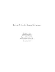
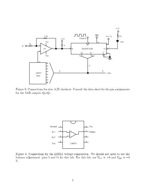
+5 VIN10k4.7MVcc2 +3113 -Vee7+5 V1k7DClock In974LS503 SARQ0 --- Q73 14Start10CC__E1Vcc (+5)1682470LED161__ 8AD557<strong>DAC</strong>8/8/LEDs8Figure 3: Connections for slowA/Dcheckout. Consult the data sheet for the pin assignmentsfor the SAR outputs Q 0 {Q 7 .Ground18VccIn 1In 223+_76OutputVee4 5LM311Figure 4: Connections for the LM311 voltage compara<strong>to</strong>r. We should not need <strong>to</strong> use thebalance adjustment (pins 5 and 6) for this lab. For this lab, use VCC +6 and VEE ,6V.3