Double Insulated 10" Bench Top Table Saw Instruction Manual
Double Insulated 10" Bench Top Table Saw Instruction Manual
Double Insulated 10" Bench Top Table Saw Instruction Manual
- No tags were found...

You also want an ePaper? Increase the reach of your titles
YUMPU automatically turns print PDFs into web optimized ePapers that Google loves.
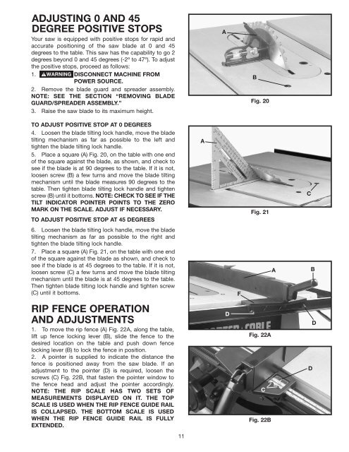
ADJUSTING 0 AND 45DEGREE POSITIVE STOPSYour saw is equipped with positive stops for rapid andaccurate positioning of the saw blade at 0 and 45degrees to the table. This saw has the capability to go 2degrees beyond 0 and 45 degrees (-2º to 47º). To adjustthe positive stops, proceed as follows:1. DISCONNECT MACHINE FROMPOWER SOURCE.2. Remove the blade guard and spreader assembly.NOTE: SEE THE SECTION “REMOVING BLADEGUARD/SPREADER ASSEMBLY.”3. Raise the saw blade to its maximum height.ABFig. 20TO ADJUST POSITIVE STOP AT 0 DEGREES4. Loosen the blade tilting lock handle, move the bladetilting mechanism as far as possible to the left andtighten the blade tilting lock handle.5. Place a square (A) Fig. 20, on the table with one endof the square against the blade, as shown, and check tosee if the blade is at 90 degrees to the table. If it is not,loosen screw (B) a few turns and move the blade tiltingmechanism until the blade measures 90 degrees to thetable. Then tighten blade tilting lock handle and tightenscrew (B) until it bottoms. NOTE: CHECK TO SEE IF THETILT INDICATOR POINTER POINTS TO THE ZEROMARK ON THE SCALE. ADJUST IF NECESSARY.TO ADJUST POSITIVE STOP AT 45 DEGREES6. Loosen the blade tilting lock handle, move the bladetilting mechanism as far as possible to the right andtighten the blade tilting lock handle.7. Place a square (A) Fig. 21, on the table with one endof the square against the blade as shown, and check tosee if the blade is at 45 degrees to the table. If it is not,loosen screw (C) a few turns and move the blade tiltingmechanism until the blade is at 45 degrees to the table.Then tighten blade tilting lock handle and tighten screw(C) until it bottoms.AFig. 21CFABRIP FENCE OPERATIONAND ADJUSTMENTS1. To move the rip fence (A) Fig. 22A, along the table,lift up fence locking lever (B), slide the fence to thedesired location on the table and push down fencelocking lever (B) to lock the fence in position.2. A pointer is supplied to indicate the distance thefence is positioned away from the saw blade. If anadjustment to the pointer (D) is required, loosen thescrews (C) Fig. 22B, that fasten the pointer window tothe fence head and adjust the pointer accordingly.NOTE: THE RIP SCALE HAS TWO SETS OFMEASUREMENTS DISPLAYED ON IT. THE TOPSCALE IS USED WHEN THE RIP FENCE GUIDE RAILIS COLLAPSED. THE BOTTOM SCALE IS USEDWHEN THE RIP FENCE GUIDE RAIL IS FULLYEXTENDED.DFig. 22ACFig. 22BDD11