Double Insulated 10" Bench Top Table Saw Instruction Manual
Double Insulated 10" Bench Top Table Saw Instruction Manual
Double Insulated 10" Bench Top Table Saw Instruction Manual
- No tags were found...

Create successful ePaper yourself
Turn your PDF publications into a flip-book with our unique Google optimized e-Paper software.
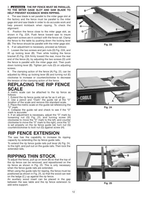
3. THE RIP FENCE MUST BE PARALLELTO THE MITER GAGE SLOT AND SAW BLADE TOHELP PREVENT KICKBACK WHEN RIPPING.4. The saw blade is set parallel to the miter gage slot atthe factory and the fence must be parallel to the mitergage slot and saw blade in order to do accurate work andhelp prevent kickback when ripping. To check thealignment:5. Position the fence close to the miter gage slot, asshown in Fig. 22A. Push fence toward saw to insurealignment screws are in contact with the fence rail. Clampthe fence to the table by pushing down the locking lever(B). The fence should be parallel with the miter gage slot.6. If an adjustment is necessary, proceed as follows:7. Loosen the two screws and jam nuts (D) Fig. 22A, andlift up locking lever (B). Then while holding the fencebracket (F) Fig. 22A firmly toward the rear, move the rearend of the fence (A), by adjusting the two screws (D) untilthe fence is parallel with the miter gage slot. Then pushdown locking lever (B). Tighten jam nuts (D) on adjustingscrews.8. The clamping action of the fence (A) Fig. 23, can beadjusted by lifting up locking lever (B) and turning nut (E)clockwise to increase or counterclockwise to decreasethe tension of the clamping action of the fence.REPLACING THE RIP FENCESCALEA metric scale can be attached to the rip fence asfollows:1. Extend the rip fence guide rail as far as it will go.2. Use a pencil and “mark” the guide rail at the “0”location of the scale and remove the standard scale.3. Place the metric scale on the guide rail referencing the“0” mark.4. Collapse the guide rail and check to see if the “0”mark is accurate.5. If an adjustment is necessary, adjust the “0” mark byloosening nut (G) Fig. 23, and turning screw (H)clockwise to move the “0” mark to the left, and counterclockwise to move the “0” mark to the right, once the “0”is set properly on the rip fence guide rail, turn nut (G)counterclockwise to lock nut (G) against screw (H).RIP FENCE EXTENSIONThe saw has the capability to increase its rippingcapacity by extending the rip fence guide rails.To extend the rip fence guide rails pull lever (A) Fig. 24,to the right, and pull out on the guide rails. Then lock theextended rails.HGBFig. 23AFig. 24CERIPPING THIN STOCKTo adjust the fence, pull up on lever (B) so that the top ofthe rip fence can be removed, and repositioned on therip fence as shown in Fig. 25. This is only necessarywhen the fence guide rails are extended.When using the guide rails for ripping, the fence must bepositioned as shown in Fig. 25, so that the wood can reston the ledge (C,) up against the rip fence.An auxiliary wood insert can be placed in the gapbetween the saw table and the rip fence extension toadd extra support.Fig. 25B12