Double Insulated 10" Bench Top Table Saw Instruction Manual
Double Insulated 10" Bench Top Table Saw Instruction Manual
Double Insulated 10" Bench Top Table Saw Instruction Manual
- No tags were found...

Create successful ePaper yourself
Turn your PDF publications into a flip-book with our unique Google optimized e-Paper software.
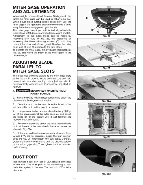
MITER GAGE OPERATIONAND ADJUSTMENTSWhen straight cross-cutting (blade set 90 degrees to thetable) the miter gage can be used in either table slot.When bevel cross-cutting (blade tilted) only use themiter gage in the right table slot where the blade is tiltedaway from the miter gage and your hands.This miter gage is equipped with individually adjustableindex stops at 90 degrees and 45 degrees right and left.Adjustment to the index stops can be made byloosening lock nuts (B) Fig. 26, and tightening orloosening the three adjusting screws (C) until theycontact the other end of stop guard (D) when the mitergage is at 90 and 45 degrees to the saw blade.To operate the miter gage, simply loosen lock knob (E)Fig. 26, and move the body of the miter gage to thedesired angle.EBCFig. 26BDAADJUSTING BLADEPARALLEL TOMITER GAGE SLOTSThe blade was adjusted parallel to the miter gage slotsat the factory. In order to insure accurate cuts and helpprevent kickback when cutting, this adjustment shouldbe periodically checked and if necessary, adjusted asfollows:1. DISCONNECT MACHINE FROMPOWER SOURCE.2. Raise the blade to its highest position and adjust theblade so it is 90 degrees to the table.3. Select a tooth on the saw blade that is set to theleft. Mark this tooth with a pencil or marker.4. Using a combination square, place the body (A) Fig.27, of the square against the miter gage slot and adjustthe blade (B) of the square until it just touches themarked tooth, as shown.5. Rotate the blade and check the same marked bladetooth at the rear of the saw table in the same manner, asshown in Fig. 27A.6. If the front and back measurements, shown in Figs.27 and 27A, are not identical, loosen the four trunnionbolts (A) Fig. 28, underneath the saw table. Carefullygrasp and move the saw frame until the blade is parallelto the miter gage slot. Then tighten the four trunnionbolts securely.Fig. 27Fig. 27AAFig. 28BDUST PORTThe saw has a dust port (B) Fig. 28A, located at the rearof the saw. The dust port is for connecting a dustcollection system to the saw. The port is 2-1/2" outsidediameter.Fig. 28A13