Motor Control Lighting Development Tools Motor ... - ICC Media GmbH
Motor Control Lighting Development Tools Motor ... - ICC Media GmbH
Motor Control Lighting Development Tools Motor ... - ICC Media GmbH

You also want an ePaper? Increase the reach of your titles
YUMPU automatically turns print PDFs into web optimized ePapers that Google loves.
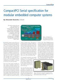
TOOLS & SOFTWARECreating a flexible solution fortesting 802.11ad devicesBy Spiro Moskov, Agilent TechnologiesThis article outlinessome of the key problemsin testing and presents asystem configuration thatenables detailed testingand analysis of802.11 ad devices.Figure 1. This example ofEVM measurement wascreated using a test systemconfiguration similar tothe one shown in figure 2. The IEEE 802.11ad standard is an up-andcomingtechnology expected to enable wirelessconnectivity of up to 7 Gbit/s in data, displayand audio applications. Per the January 2011draft standard, signals will occupy the unlicensed60 GHz frequency band, and compliantdevices will provide backward compatibilitywith the 802.11 standard. As a result, tri-banddevices will operate at 2.4, 5.0 and 60 GHz.Many companies have launched product developmentprojects and developers face challengesthat stretch from system-level design toverification testing.For example, thorough testing of 802.11adtransmitters and receivers requires three essentialelements: arbitrary waveform creation;frequency conversion; and signal, modulationand spectrum analysis. In the development ofnew 802.11ad products, testing must addressthe transmitter and receiver portions of eachdevice. In a tri-band device, signals have threekey attributes: they operate at 2.4, 5.0 and 60GHz; carry various modulation schemes; andhave bandwidths in either the 20 MHz range(802.11a/g/n and 802.11b/g), 40 MHz range(802.11n), up to 80/160 MHz contiguous ornoncontiguous (802.11ac), or 2.0 GHz(802.11ad). At various points within the radioblock diagram the signals may operate in thebaseband, intermediate frequency (IF) or radiofrequency (RF) range.As a general problem statement, the IEEE802.11ad draft standard includes specific measurementswith expected values for transmittersand receivers. Examples include receiver minimumsensitivity and transmit error vectormagnitude (EVM; see figure 1). Going beyondthe draft specifications, design teams may alsowant to verify the overall performance of anew 802.11ad device. In such cases, they willwant to look at important measurements suchas match, gain or loss through frequency converters,and nonlinear tests such as p1dB undervarious operating conditions. Thorough testingof 802.11ad transmitters and receivers at baseband,IF and RF requires three essential elements:arbitrary waveform creation; frequencyconversion; and signal, modulation and spectrumanalysis. The flexible and configurabletest setup shown in figure 2 covers all these requirements.Starting at the top of figure 2, waveform creationat baseband frequencies is accomplishedwith specialized software and an arbitrarywaveform generator (AWG). In this case a 4.2GS/s AWG is used to create highly accuratesimulations of standard-compliant signals thatcan be applied to transmitters and receivers.Key features of the AWG include 12-bit resolution,up to 64 MS memory and advanced sequencingcapabilities. The AWG is availablewith one or two output channels, and twounits can be linked to provide four synchronizedoutputs. Each output channel has up to1 GHz modulation bandwidth and up to 2GHz I/Q modulation at carrier frequencies ofup to 1.5 GHz. Characterization of device performanceversus the standard also requiresgeneration of impaired or corrected signalsthat mimic real-world issues such as fading,distortion, I/Q skew and carrier-to-noise problems.One way to accomplish this is with waveform-creationsoftware that can downloadwaveforms into AWG memory. Examples includeSystemVue and Signal Studio from Agilentas well as MATLAB from The MathWorks.Moving down the figure, IF-band frequencyconversion is accomplished with an upconverter.This configuration uses a vector signal generatorwith optional wideband external I/Q inputs.As shown, the AWG is used to directly drivethe internal I/Q modulator with I/Q modulationbandwidth of up to 2 GHz. A custom-designedupconverter provides frequency conversion tothe RF range. A high-precision microwave analogsignal generator provides a stable LO signalfor the upconverter.In the lower half of the figure, the custom-designeddownconverter provides frequency translationto the IF band. In this configuration ahigh-performance oscilloscope (up to 32 GHzanalog bandwidth) and an advanced signal21 April 2013