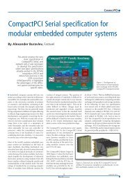
MICROCONTROLLERSFigure 1. Software for handling the partial RAM test during run-timeFigure 2. When the data is read, its parity is computed and checked against the reference value.this solution has proven to be effective and isnowadays a common industry practice, it hasa number of drawbacks. Let’s consider it fromthe software engineering standpoint first. Wewill not review the benefits of structured programming,but let’s look at the constraints relatedto this implementation. Encapsulationissues: the C modules must have part of theirinternal variables promoted as global and thusno longer subject to the sanity checks done bythe compiler against cross modules accesses.Low tasks isolation and poor modularization:the test structure imposes a test access to eachsafety critical software module and makes theaddition of new features more complex. Wecan also consider potentially higher risks ofdata corruption if we link its probability tothe number of read/write accesses. This is mitigatedby inverse redundant storage of safetycritical variables, but this in turn increases thesize of the area to be “Class B tested”.From the MCU resources standpoint, the testimplementation consumes ROM and RAM, aswell as CPU bandwidth: if the core is temporarilyunable to absorb the test burden ontop of its regular processing task, the test mighthave to be stopped during a computationallycritical operating phase of the appliance. Finally,a run-time RAM check affects real-time responsiveness(it can delay or even suspendany other ISR) and can conflict with low-latencyor emergency tasks requirements. Thelength of the test routine cannot be minimized:a minimum number of consecutive memorylocations must be evaluated for coupling faultscoverage. And the complexity increases if thesoftware has to manage address descramblingto be in line with the physical memory layout.How software handles the partial RAM testduring run-time is shown in figure 1. TheIEC60730 standard proposes an alternative solutionconsisting of a hardware parity bit. Althoughthis is standard procedure for DRAMmemories, this is quite unusual in general purposemicrocontrollers; advanced silicon processnodes have made such features more cost-effective.The solution consists of adding oneparity bit per memory location: the parity iscomputed at the time the memory is writtenand stored in parallel with the data. When thedata is read, its parity is computed and checkedagainst the reference value, as represented infigure 2. In case of a difference, either due todata or parity bit corruption, an interrupt orexception signal line is asserted.The core then handles the error in a dedicatedsafety ISR and shuts down the appliance properly.In a second step, the core may re-start theapplication (hot reset) or definitively stop theequipment with a maintenance code displayed.The benefits of this implementation are obvious.Class B RAM check is made completelytransparent: Software practices do not need tobe compromised, no MCU vendor specifictest routine has to be developed, other than aglobal fault handling function which must bepresent in any case, no specific RAM partitioningand linker script is needed, CPU bandwidthis fully available for the application (theparity computation does not increase the memoryreading latency), and real-time behavioris optimum. As a final benefit, this eliminatesthe need for the full RAM check at start-upand lowers the boot time, since the paritycheck is active right after the power-on reset.Brushless motors are used in appliances becauseof their high efficiency, silent operation androbustness, but complex control and dedicatedPWM peripherals are necessary. Particular careis needed for fault protection and safe shutdown.For this purpose, the RAM parity errorchecking mechanism improves reliability andresponse time. Rather than managing safeshut-down by software, the parity error signalis directly routed to the PWM peripherals totrigger an emergency shut-down automaticallyand avoid system clock and software-relateddelay. The block diagram in figure 3 presents apractical implementation.Care must also be taken to monitor other criticalsystem parameters. A power supply monitoringsystem can be programmed to issue aninterrupt if the Vdd voltage drops below a preprogrammedvalue. Similarly, a clock securitysystem verifies that the main clock is operatingproperly and issues an interrupt in case of ab-April 2013 28
MICROCONTROLLERSFigure 3. Block diagram of a practical implementationnormal operation. Additionally, the Cortexcore provides a signal at the chip level to indicatewhen the core enters lockup state, whichcan take place when a fault occurs inside thehard fault or the NMI handlers, or when a busfault occurs during the boot sequence. Thesethree events, together with the parity, aremerged for asserting an internal emergencyshutdown signal, which is itself OR’ed withthe external break input. A failsafe clock circuitryis also required by the norm. This ispartly achieved using a clock security systemperipheral (CSS) that automatically switchesthe main clock back to an internal high-speedoscillator in case of crystal failure. Additionally,it is necessary to provide a means to monitorthe external clock by comparing the expectedexternal frequency with an internal one. Thereal-time clock timer can be supplied by theLSI (low speed internal) internal RC oscillatorto measure the main system clock preciselyenough to detect a 50% change due to operationon the crystal sub-harmonics. At systemlevel, this can save the cost of circuitry able todo 50/60Hz mains zero-crossing detection.The norm proposes an independent time-slotmonitoring to prevent any CPU run-away incase of a program counter malfunction: this isthe duty of the watchdog timer, which is embeddedin most MCUs. Nonetheless, it is statedthat it must be fully independent. For this reason,the STMicroelectronics Cortex-M basedSTM32 family has two watchdogs: a regularwindow watchdog running on the main clocksource, and a second watchdog, using an independentinternal oscillator and started withan option byte located in flash memory. Thisensures that at least one watchdog will beactive in case of crystal failure and whateverthe clock circuitry configuration.Finally, the MCU embeds a 32-bit hardwareCRC calculation unit, which significantly speedsupthe flash content integrity check and reducesthe related CPU load (spend during run-time)to a negligible value. This peripheral can evenbe fed by the DMA controller. It gives the possibilityto have the flash integrity check doneas a background task during run-time. Product News Infineon: easy switch from 8-bit to 32-bitwith XMC1000 Industrial MCUsAt Embedded World, Infineon Technologies presentedsamples of its new XMC1000 industrial 32-bit microcontroller family which provides systemdesigners with strong incentive to switch from 8 to32 bit MCU architecture. With XMC1000, Infineonoffers a fully-featured 32-bit alternative for hitherto8-bit users by combining the ARM Cortex-M0processor core with powerful peripherals, high productivitydesign tools and costs typical of 8-bit devicesbased on production using state-of-the-art,65nm embedded Flash technology on 300mmwafers.News ID 16910 Holtek: Tinypower MCU for 3D Glassescomes in 16-pin SSOP packageHoltek’s new HT45FH3T MCU comes fully integratedwith the necessary high voltage circuitswhich are a requirement for 3D Glasses applications.In addition to including all the originalfunctions of the previous HT45F3T, this newdevice also includes a 3V low dropout voltage regulatorand four level shift functions. These featuresextensively reduce the need for peripheral components,resulting not only in reduced cost but alsoreduced PCB areas.News ID 1698829 April 2013