SOKIII Installation - Carefree of Colorado
SOKIII Installation - Carefree of Colorado
SOKIII Installation - Carefree of Colorado

Create successful ePaper yourself
Turn your PDF publications into a flip-book with our unique Google optimized e-Paper software.
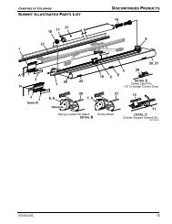
<strong>Carefree</strong> <strong>of</strong> <strong>Colorado</strong>SETTING THE DEFLECTOR MOUNTING BRACKETS<strong>SOKIII</strong>1“ min, 12” max(typ)3/8” MaxDetail A8”-9”7”max. 1”min.Optional Spacer#12 x 1 Self Drilling ScrewEvenly SpaceEvenly SpaceDo Not Use Slot forMounting ScrewsDetail BBracket CoverDeflectorMounting Bracket(qty: 3 for units 282” or less5 for units 283” or Longer)SOKiii007Figure 12. Setting the Deflector Brackets.NOTE: If the thickness <strong>of</strong> the room flange exceeds the 3/8" maximum as shown in detail A, a 1/4"spacer is available. Spacer is ordered separately.4. Vertically position the bottom <strong>of</strong> deflector brackets on the room face 8"-9" below the centerline <strong>of</strong> the awningrail. Horizontally position the brackets as shown above.NOTE: The bottom <strong>of</strong> the brackets must not be positioned more than 7" below the top <strong>of</strong> theflange or less than 1" from the top <strong>of</strong> the room5. Horizontally position the brackets as shown above. The center bracket must be positioned so that the centersplice <strong>of</strong> the defector will rest near the center <strong>of</strong> the bracket. For units with 5 brackets; the middle bracketsmay be adjusted ± 12" to avoid vents or other projections.6. Attach the brackets. Using a quality silicone sealant, coat the mounting surface <strong>of</strong> the bracket with particular attentionaround the mounting holes. Use #12 x 1 self-drilling screws. (5 per bracket).7. Snap the bracket cover on to the bracket to cover the screw heads. The tab on the back <strong>of</strong> the cover goesinto the slotted hole <strong>of</strong> the bracket.NOTE: If it is necessary to remove the cover after installation, slidea small pin (e.g. paper clip) in the end under the cover. Liftthe locking tab and gently pull out the end <strong>of</strong> the cover.Repeat for other side <strong>of</strong> the cover.PinLockingTabSOK3013Figure 13. Removing theCover.8 052557-001r3