Patio Awning Installation Manual - Carefree of Colorado
Patio Awning Installation Manual - Carefree of Colorado
Patio Awning Installation Manual - Carefree of Colorado

Create successful ePaper yourself
Turn your PDF publications into a flip-book with our unique Google optimized e-Paper software.
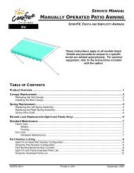
INSTALLATION MANUALMANUALLY OPERATED PATIO AWNINGRVSPIRIT FX, FIESTA AND SIMPLICITY AWNINGSThese instructions apply to all models listed. Details and procedures unique to a specificmodel are labeled appropriately. For optional equipment, refer to the instructions includedwith the option.TABLE OF CONTENTSComponent Checklist.................................................................................................................... 1<strong>Installation</strong> ..................................................................................................................................... 2General Layout .......................................................................................................................................2Installing an awning rail (if required).......................................................................................................2Assembling the <strong>Awning</strong> ..........................................................................................................................3Mounting the Bottom Mounting Brackets................................................................................................3Mounting the <strong>Awning</strong> ..............................................................................................................................4Installing the Stop Bolt....................................................................................................................5Securing the Fabric ........................................................................................................................5Installing the Rubber Bumpers .......................................................................................................5Thin-Lite Power (Spirit FX only)..............................................................................................................6052876-005 Printed in USA May, 2006
PROPRIETARY STATEMENTThe manual <strong>Patio</strong> <strong>Awning</strong> is a product <strong>of</strong> <strong>Carefree</strong> <strong>of</strong> <strong>Colorado</strong>, located in Broomfield, <strong>Colorado</strong>, USA. Theinformation contained in or disclosed in this document is considered proprietary to <strong>Carefree</strong> <strong>of</strong> <strong>Colorado</strong>.Every effort has been made to ensure that the information presented in the document is accurate andcomplete. However, <strong>Carefree</strong> <strong>of</strong> <strong>Colorado</strong> assumes no liability for errors or for any damages that resultfrom the use <strong>of</strong> this document.The information contained in this manual pertains to the current configuration <strong>of</strong> the models listed on thetitle page. Earlier model configurations may differ from the information given. <strong>Carefree</strong> <strong>of</strong> <strong>Colorado</strong>reserves the right to cancel, change, alter or add any parts and assemblies, described in this manual,without prior notice.<strong>Carefree</strong> <strong>of</strong> <strong>Colorado</strong> agrees to allow the reproduction <strong>of</strong> this document for use with <strong>Carefree</strong> <strong>of</strong> <strong>Colorado</strong>products only. Any other reproduction or translation <strong>of</strong> this document in whole or part is strictly prohibitedwithout prior written approval from <strong>Carefree</strong> <strong>of</strong> <strong>Colorado</strong>.SAFETY INFORMATIONWARNINGA WARNING INDICATES A POTENTIALLY HAZARDOUS SITUATION WHICH, IF NOT AVOIDED, COULD RESULT INDEATH OR SERIOUS INJURY AND/OR MAJOR PROPERTY DAMAGE.CAUTIONA CAUTION INDICATES A POTENTIALLY HAZARDOUS SITUATION THAT MAY CAUSE MINOR TO MODERATEPERSONAL INJURY AND/OR PROPERTY DAMAGE. IT MAY ALSO BE USED TO ALERT AGAINST UNSAFE PRACTICES.NOTE: A note indicates further information about a product, part, or step.Tip:A tip provides helpful suggestions.Safety Notes:• Always disconnect battery or power source before working on or around the electrical system.• Always wear appropriate safety equipment (i.e. goggles).• Always use appropriate lifting devices and/or helpers when lifting or holding heavy objects.• When using fasteners, use care to not over tighten. S<strong>of</strong>t materials such as fiberglass and aluminumcan be "stripped out" and lose the ability to grip.REFERENCE PUBLICATIONS LOCATED @ www.carefree<strong>of</strong>colorado.com:052876-005 <strong>Patio</strong> <strong>Awning</strong> <strong>Installation</strong> <strong>Manual</strong>052876-201 <strong>Patio</strong> <strong>Awning</strong> Owner's <strong>Manual</strong>052876-301 <strong>Patio</strong> <strong>Awning</strong> Service <strong>Manual</strong><strong>Awning</strong> Accessory <strong>Manual</strong>s:052787-003 Thin–Lite <strong>Installation</strong> & Operation <strong>Manual</strong>052796-001 Power Pack <strong>Installation</strong>052806-003 Automatic <strong>Awning</strong> Support052807-004 Rafter VI <strong>Installation</strong> & Operation <strong>Manual</strong>052959-001 Rafter VII <strong>Installation</strong> & Operation <strong>Manual</strong><strong>Carefree</strong> <strong>of</strong> <strong>Colorado</strong> 2145 W. 6 th Avenue Broomfield, CO 80020a Scott Fetzer company303-469-3324 ♦ www.carefree<strong>of</strong>colorado.com
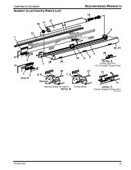
<strong>Carefree</strong> <strong>of</strong> <strong>Colorado</strong> <strong>Installation</strong> <strong>Manual</strong> MANUAL PATIO AWNINGCOMPONENT CHECKLIST3545621101112 13 14 1516817791819SF002 ITEM DESCRIPTIONFigure 1. Component Checklist.QTY NOTEBASIC ASSEMBLY 1 <strong>Awning</strong> Rail 1 3 2 Roll Bar Assy 1 1 3 Arm Assy, LH 1 1 4 Arm Assy, RH 1 1 5 Upper Mounting Bracket REF 2 6 Upper Bracket Stand-<strong>of</strong>f, Optional 2 3 7 Lower Mounting Bracket 2 8 Lower Bracket Shim, Optional 2 3 9 Lower Bracket Stand-<strong>of</strong>f, Optional 2 3 10 Lag Screw 1/4 x 3 4 11 Lag Screw 1/4 x 2 1/2 4 12 Screw, Quadrex Head 1/4-20 x 7/16 4 13 Lock Washer 1/4 2 14 Nut, Cap 1/4-20 2 15 Screw, Hex Washer Head #6 x 3/8 2 16 Bumpers (set <strong>of</strong> 2) 1 17 Pull Wand 1 18 Carport Ground Stake 4 4 19 Owner's <strong>Manual</strong> 1 5Notes: 1. <strong>Awning</strong> configuration is specified at time <strong>of</strong> order, including awning length, fabric, color etc. Checkawning assembly against original purchase order.2. The upper mounting bracket is pre assembled with the arm assy and is shown for reference only.3. <strong>Awning</strong> rail (item 1), and the upper and lower stand-<strong>of</strong>f brackets and shim (items 6, 8 & 9) must beordered separately.4. Carport Ground Stakes are optional must be ordered separately.5. Place Owner's <strong>Manual</strong> with RV owner information. <strong>Installation</strong> manual, if included, is for installerreference.052876-105 1
MANUAL PATIO AWNING <strong>Installation</strong> <strong>Manual</strong> <strong>Carefree</strong> <strong>of</strong> <strong>Colorado</strong>INSTALLATIONGENERAL LAYOUT5”(approx.)Fabric Width5”(approx.)Ro<strong>of</strong> Line90 o 90 oBrake Lever (ref)<strong>Awning</strong> RailUpper MountingBracket<strong>Awning</strong> Width(in 12” increments)Figure 2. General Layout.Floor LineINSTALLING AN AWNING RAIL (IF REQUIRED)1. Position the awning rail along the ro<strong>of</strong> line (line where ro<strong>of</strong> and wallmeet) or a minimum <strong>of</strong> 6" above the upper edge <strong>of</strong> the door or windowsthe awning is covering. <strong>Awning</strong> rail must be level and parallel with thefloor line <strong>of</strong> the vehicle.2. After determining mounting position, mark the position with a chalk line.3. Seal the back <strong>of</strong> the rail with silicone sealant or putty tape.4. Align the awning rail onto the wall and secure with #10 x 3/4” screws.Use all the attachment holes in the rail.5. Use a screwdriver to spread open the left end <strong>of</strong> the awning rail on theinstallation side.Bottom MountingBracketSF003Spread openthe end <strong>of</strong> theawning railFigure 3. Installing the<strong>Awning</strong> Rail.T0012a6. File any sharp edges or burrs from the end <strong>of</strong> the rail. This will help protect the awning fabric fromdamage during installation.7. Spray inside the awning rail track with silicone lubricant.2 052876-005
<strong>Carefree</strong> <strong>of</strong> <strong>Colorado</strong> <strong>Installation</strong> <strong>Manual</strong> MANUAL PATIO AWNINGASSEMBLING THE AWNINGCAUTIONDO NOT REMOVE THE FOLLOWING ITEMS UNTIL INSTRUCTED TO DO SO IN THE INSTRUCTIONS. 1) TAPE AROUNDTHE CANOPY; 2) THE SAFETY PIN IN THE ROLL BAR (THIS IS HOLDING THE PRE-WOUND SPRING TENSION); OR,THE NYLON STRAP HOLDING THE ROLL BAR BRAKE LEVER. REMOVING THESE ITEMS PREMATURELY MAYCAUSE PERSONAL INJURY, DAMAGE TO THE AWNING AND CAUSE THE AWNING TO NOT OPERATE CORRECTLY.1/4-20 x 7/16Quadrex DriveScrewStorage LockLeft Arm Assy1/4-20 x 7/16Quadrex DriveScrewRemote LockSpirit & Fiesta OnlyRight Arm AssyRemote LockDETAIL AOpen PositionSpirit & Fiesta OnlyFigure 4. Assembling the <strong>Awning</strong>.1. On a flat surface, layout the arms and rollbar assembly.• Position the rollbar with the fabric oriented as shown over the top with the edge toward the coach.The brake lever must be on the right side.• For Spirit and Fiesta – The right arm assembly has the remote lock.2. For All Models: Slide the left arm into the left end plug <strong>of</strong> the roll bar. Align the holes and secure usingone (1) 1/4-20 x 7/16 Quadrex Drive screw.3. For Simplicity: Repeat step 2 for the right arm assembly.4. For Spirit and Fiesta: Hook the remote lock over the brake lever while sliding the arm into the right end plug.Align the holes in the arm and end plug and secure using one (1) 1/4-20 x 7/16 Quadrex Drive screw.Tip: Release the travel lock and slide the remote lock up until it protrudes over the arm. Hook theremote over the brake lever. Allow the remote lock to slide back into the channel while sliding the arminto the end plug. REMEMBER TO CLOSE THE TRAVEL LOCK WHEN DONE.5. Measure and confirm the width <strong>of</strong> the awning. The distance is measured from centerline <strong>of</strong> arm tocenterline <strong>of</strong> arm. (Refer to Figure 2 on page 2.)<strong>Awning</strong> ArmMOUNTING THE BOTTOM MOUNTING BRACKETS1/4 x 2 1/2 Lag Screw1. On the awning rail, mark the position <strong>of</strong> the centerlines <strong>of</strong> thearms. Ensure that the arms will not interfere with any lights,vents or other obtrusions.2. Using a non-permanent method <strong>of</strong> marking such as a chalkline, mark a perpendicular line from the awning rail down tothe floor line. This is the centerline <strong>of</strong> the arms.3. Position and attach the bottom mounting brackets. These shouldbe centered on the lines made in the previous step and MUST beattached to the structure at the floor line <strong>of</strong> the vehicle. Attachusing 1/4 x 2/12 lag screws.NOTE: The bracket is made to straddle the trim found at thefloor line. A flat shim is available for mounting to flatareas without trim. If it is necessary to space thebracket out from the wall, a spacer bracket is available.Shim and spacer must be ordered separately.Optional ShimOptional Stand<strong>of</strong>fSF004SF005Figure 5. Mounting the Bottom Brackets.052876-105 3
MANUAL PATIO AWNING <strong>Installation</strong> <strong>Manual</strong> <strong>Carefree</strong> <strong>of</strong> <strong>Colorado</strong>MOUNTING THE AWNING1. Measure the distance from the awning rail to the bottommounting brackets.2. Adjust the arm length so the distance from the center <strong>of</strong> the rollerto the foot is approximately equal to the measurement in step 1.• To adjust arm length, open the arm handle and slide the lowerchannel up or down as required. Close the handle and slidethe lower channel until the locking pin clicks into the nearestpositioning hole.3. Remove the tape from the canopy. Unwrap a small portion <strong>of</strong>canopy but not more than one wrap.The next step will require two additional people. One to feed thecanopy into the awning rail; two to "walk" the arms while thecanopy is slid into position.4. Slide the polycord edge <strong>of</strong> the canopy (or alumiguard) into theawning rail. Continue to "walk" the arms and canopy downthe rail until the arms are in line with the centerline marksmade previously.5. Lift the arm up and secure the foot into the bottom bracket.Repeat for both arms.6. Firmly grasp the roll bar and remove the safety cotter pin from the left end <strong>of</strong> the roll bar. Allow thefabric to SLOWLY roll up.CAUTIONUSE CARE WHEN REMOVING THE COTTER PIN. THE PIN IS HOLDING THE PRE-WOUND TENSION OF THE SPRING.FAILURE TO SECURELY HOLD THE ROLLBAR MAY ALLOW THE ROLLBAR TO RAPIDLY ROLL UP AND CAUSEPERSONAL INJURY OR DAMAGE.7. Remove the nylon strap holding the brake lever.8. Carefully open the awning 12 – 18 inches to provide accessto the upper mounting bracket.• For Simplicity: Unsnap the arm retaining strap andmove the brake lever into the OPEN position.• For Spirit and Fiesta: Open the arm storage lock andmove the remote lock up.• USE THE PULL STRAP and pull the awning out.9. Loosen the black locking knob on the upper brace.10. Slide the upper portion <strong>of</strong> the brace up so that the uppermounting bracket straddles the awning rail.11. Center the bracket on the arm centerline drawn earlier.12. Attach the upper bracket using two (2) 1/4 x 3 lag screws.The screws must go into the vehicle structure. It isacceptable that the screws go through the flat portion <strong>of</strong> theawning rail.13. Repeat steps 9 through 12 for the other arm.1/4 x 3Lag ScrewsSpring LoadedLeverArm LatchFigure 7. Attaching Upper MountingBracket.NOTE: The bracket is made to straddle the awning rail. If it is necessary to space the bracketout from the wall, a spacer bracket is available and must be ordered separately.SF007Figure 6. Adjusting Lower Arm.<strong>Awning</strong> ArmUpper MountingBracketOptional Stand<strong>of</strong>fBlack LockingKnobSF0064 052876-005
<strong>Carefree</strong> <strong>of</strong> <strong>Colorado</strong> <strong>Installation</strong> <strong>Manual</strong> MANUAL PATIO AWNINGInstalling the Stop Bolt1. Retract the awning.2. Observe if the centerline <strong>of</strong> the roll bar is level withor slightly higher than the centerline <strong>of</strong> the awningrail. (Refer to page 2.) The bottom <strong>of</strong> the roll barmust not be higher than the awning rail.3. Adjust the arm length as required. Open the armhandle and slide the lower channel up or down asrequired. Close the handle and slide the lowerchannel until the locking pin clicks into the nearestpositioning hole.4. Mark the position stop hole that is directly belowthe upper channel.Figure 8. Stop Bolt.5. From the inside <strong>of</strong> the channel, insert a 1/4-20 x 7/16 quadrex head screw with a star washer through the hole.Slide the centering spacer over the screw and inside the mounting hole. Secure with a 1/4-20 cap nut.Tip: It may be necessary to lift the upper channel to tighten the cap nut.6. Repeat for other arm.Securing the Fabric1. Roll the awning in and out several times to make sure that the fabric is square on the rollbar.2. (refer to Figure 9) Secure the canopy fabric or Alumaguard using one, #6 x 3/8" hex head screw atboth sides <strong>of</strong> the awning.<strong>Awning</strong> Rail1"Polyrod<strong>Awning</strong> Rail1"1/4-20 Cap NutPolyrodSpacerArm LatchHole BelowUpper Channel<strong>Awning</strong> Rail1/4-20 x 7/16Quadrex Head Screw1/4” Star WasherSF008Fabric#6 x 3/8ScrewS<strong>of</strong>t ConnectUniguard#6 x 3/8ScrewAlumaguard#6 x 3/8ScrewFabricE0014Figure 9. Securing the Fabric.2.1 For vinyl awnings, place screw through awning rail, polyrod and canopy approximately 1” in fromthe end <strong>of</strong> the fabric.2.2 For Uniguard awnings, place screw through awning rail, polyrod and the s<strong>of</strong>t connect materialapproximately 1" in from the end <strong>of</strong> the fabric.2.3 For Alumaguard awnings, place screw on the outer edge <strong>of</strong> the Alumaguard.Installing the Rubber BumpersBecause <strong>of</strong> vibration and movement, it may be necessary to "tighten" the awning arms when stored in thetravel position. Two rubber bumpers are provided for this purpose.1. Open the awning to expose the top <strong>of</strong> the upper brace.2. Peel and stick a rubber bumper on the upper brace, opposite the lockingknob as shown.3. Repeat for second arm.Rubber BumperLocking Knob (ref)Figure 10. Installing theRubber Bumpers.052876-105 5SF013
MANUAL PATIO AWNING <strong>Installation</strong> <strong>Manual</strong> <strong>Carefree</strong> <strong>of</strong> <strong>Colorado</strong>THIN-LITE POWER (SPIRIT FX ONLY)The Thin-Lite is powered by the vehicle's 12VDC system. An exterior receptacle is used for the light cord plug.1. Determine the location <strong>of</strong> the receptacle.• Locate the receptacle so that there is easy access to a 12VDC power source such as interioroverhead cabinet lights, a 12VDC switch near the door etc.• Determine the position <strong>of</strong> the receptacle so that itcan be comfortably reached for easy operation.• Position the bracket and receptacle so that whenthe cord is plugged in it does not create anobstacle (i.e. headroom for walking under).O 11/16” HoleReceptacleBracketSolderlessConnectors+12VDCGround2. At the predetermined location, drill an 11/16 inch hole#6 x 1/2 ScrewsThinLite003into the mounting surface.Figure 11. Mounting the Power Receptacle.3. Attach the receptacle to the bracket as shown.4. Route the wires from the receptacle through the hole drilled in step 2. Position the bracket andreceptacle over the hole and attach using two (2) #6 x 1/2 screws.5. Two wire clips are furnished, it is not necessary to trim or strip the wires. Place the bottom <strong>of</strong> the clip over theexisting wire in the coach; insert the wire from the receptacle into the top hole <strong>of</strong> the clip then, with a pair <strong>of</strong>pliers, squeeze the metal plate into the plastic housing then close the plastic cover. Receptacle wires aremarked (+) for 12VDC and (–) for ground.6 052876-005