TRAVEL'R ARMS AND CANOPY - Carefree of Colorado
TRAVEL'R ARMS AND CANOPY - Carefree of Colorado
TRAVEL'R ARMS AND CANOPY - Carefree of Colorado

You also want an ePaper? Increase the reach of your titles
YUMPU automatically turns print PDFs into web optimized ePapers that Google loves.
PROPRIETARY STATEMENTThe Travel'r Patio Awning is a product <strong>of</strong> <strong>Carefree</strong> <strong>of</strong> <strong>Colorado</strong>, located in Broomfield, <strong>Colorado</strong>, USA. Theinformation contained in or disclosed in this document is considered proprietary to <strong>Carefree</strong> <strong>of</strong> <strong>Colorado</strong>.Every effort has been made to ensure that the information presented in the document is accurate andcomplete. However, <strong>Carefree</strong> <strong>of</strong> <strong>Colorado</strong> assumes no liability for errors or for any damages that resultfrom the use <strong>of</strong> this document.The information contained in this manual pertains to the current configuration <strong>of</strong> the models listed on thetitle page. Earlier model configurations may differ from the information given. <strong>Carefree</strong> <strong>of</strong> <strong>Colorado</strong>reserves the right to cancel, change, alter or add any parts and assemblies, described in this manual,without prior notice.<strong>Carefree</strong> <strong>of</strong> <strong>Colorado</strong> agrees to allow the reproduction <strong>of</strong> this document for use with <strong>Carefree</strong> <strong>of</strong> <strong>Colorado</strong>products only. Any other reproduction or translation <strong>of</strong> this document in whole or part is strictly prohibitedwithout prior written approval from <strong>Carefree</strong> <strong>of</strong> <strong>Colorado</strong>.SAFETY INFORMATIONWARNINGA WARNING INDICATES A POTENTIALLY HAZARDOUS SITUATION WHICH, IF NOT AVOIDED, COULD RESULT INDEATH OR SERIOUS INJURY <strong>AND</strong>/OR MAJOR PROPERTY DAMAGE.CAUTIONA CAUTION INDICATES A POTENTIALLY HAZARDOUS SITUATION THAT MAY CAUSE MINOR TO MODERATEPERSONAL INJURY <strong>AND</strong>/OR PROPERTY DAMAGE. IT MAY ALSO BE USED TO ALERT AGAINST UNSAFE PRACTICES.NOTE: A note indicates further information about a product, part, or step.Tip:A tip provides helpful suggestions.Safety Notes: Always disconnect battery or power source before working on or around the electrical system. Always wear appropriate safety equipment (i.e. goggles). Always use appropriate lifting devices and/or helpers when lifting or holding heavy objects. When using fasteners, use care to not over tighten. S<strong>of</strong>t materials such as fiberglass and aluminumcan be "stripped out" and lose the ability to grip and hold.Reference Publications located @ www.carefree<strong>of</strong>colorado.com:'052540-002 Travel'r, Installation Manual052540-102 Travel'r Arm Extension Installation Supplement052540-201 Travel'r, Owner's Manual052540-301 Travel'r, Service Manual<strong>Carefree</strong> <strong>of</strong> <strong>Colorado</strong> 2145 W. 6 th Avenue Broomfield, CO 80020a Scott Fetzer company303-469-3324 ♦ www.carefree<strong>of</strong>colorado.com
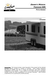
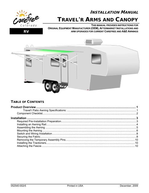
<strong>Carefree</strong> <strong>of</strong> <strong>Colorado</strong> Installation Manual <strong>TRAVEL'R</strong>PRODUCT OVERVIEWThe Travel'r provides motorized awning comfort with <strong>Carefree</strong>'s standards for looks, strength anddependability. It is the successful blend <strong>of</strong> style, quality and economy. The awning is available in two fixedpitch models.The awning roller tube and arms are made from light weight, no-rust aluminum. The awning fabric is heavyweight vinyl.Travel'r Patio Awning Specifications:MAXIMUM EXTENSION: 8 foot MAXIMUM LENGTH: 21 feetPITCH: FLAT Fixed DROP:approximately 6 inchesSTEEP Fixedapproximately 33 inchesMeasurement is from centerline <strong>of</strong> Awning Rail to centerline <strong>of</strong> rollbarMOTOR: Power: 10VDC–14VDC Circuit Rating: 20 amp motor mounted in armPOWER SOURCE: Motor and controls are routed and hardwired into the vehicle’s 12V systemEXTEND ACTUATION: Gas ShockPOSITION CONTROL: Motorized roll out/inCONTROLLER:3 position, momentary ON, center OFF SwitchCOLOR: Frame: White, BlackCanopy: Available in a Variety <strong>of</strong> fabrics and colors – refer to order sheet5”(approx)Fabric Width5”(approx)90 oTyp.6” min.Clearancefrom top <strong>of</strong>door7”Drill Area forUpper CableRoutingFor Vertical ArmPlacement refer to“Mounting the Awning”Awning Rail14.5” min.Clearancefrom top <strong>of</strong> door56 1/4”7”Drill Area forUpper CableRoutingFor Vertical ArmPlacement refer to“Mounting the Awning”Centerline<strong>of</strong> Idler Arm64 1/4”Drill Area forLower Cable RoutingAwning LengthFlat Pitch ArmCenterline<strong>of</strong> Motorized Arm#2MountingHoleFigure 1. General Layout.Drill Area forLower Cable Routing= Flat Mounting Surface Area3 1/2” x 67” - Flat Pitch3 1/2” x 59 1/2” - Steep PitchCenterline<strong>of</strong> Motorized ArmSteep Pitch Arm#2MountingHoleTravelR003052540-002r5 1
RV<strong>TRAVEL'R</strong> Installation Manual <strong>Carefree</strong> <strong>of</strong> <strong>Colorado</strong>COMPONENT CHECKLISTRollbar (ordered seperately) 1 2 3 45 68 9 10 11 1213 14 15 167 7171819OWNER'S MANUAL<strong>TRAVEL'R</strong>Travelr002aFigure 2. Component Checklist. ITEM DESCRIPTION QTY NOTEA = OEM; B = Aftermarket A B 1 Roll Bar Assembly Ordered Separately 1 1 2 Screw, Hex Washer Head #6 x 3/8 2 2 3 Tractioner 2 2 2 4 Screw, Truss Head, SQ Drive #10 x 5/8 2 2 2 5 Arm Assembly, LH 1 1 1 6 Arm Assembly, RH 1 1 1 7 Fascia 2 2 3 8 Rivet, Moly 3/16 10 10 9 Screw, Lag 1/4 x 1 1/2 10 10 10 Screw, Lag 1/4 x 2 1/2 -- 4 11 Screw, Truss Head, Sq Drive #10 x 5/8 4 12 Screw, Hex Washer Head #6 x 3/8 2 2 13 Top Mounting Bracket 2 14 Screw, Phillips Pan Head #10 x 2 2 15 Nylock Nut #10 2 16 Washer, Plastic #10 8 17 Switch,kit 1 1 18 Jumper Cable 1 1 5 19 Owner's Manual 1 1 5Notes: 1. Awning configuration is specified at time <strong>of</strong> order, including awning length, fabric, color etc. Check awningassembly against original purchase order. Arms are configuration specific and are not interchangeable.2. Screws and Tractioners are furnished with rollbar assemblies equipped with optional Alumaguard.3. Fascia for the flat pitch is longer than the fascia for the steep pitch arms.4. Quantity for item 11 = 12 for flat pitch configuration, 8 for steep pitch configuration.5. Place Jumper Cable (item 18) and Owner's Manual (item19) with RV owner information.2 052540-002r5
<strong>Carefree</strong> <strong>of</strong> <strong>Colorado</strong> Installation Manual <strong>TRAVEL'R</strong>INSTALLATIONREQUIRED PRE-INSTALLATION PREPARATION1. Park the vehicle on a flat surface and level the unit.2. IF THIS IS AN UPGRADE FOR A MANUAL PATIO AWNING: follow the awning manufacturer's instructions andremove the awning from the coach including the roll bar and canopy.a. Remove all brackets.b. Plug and seal all mounting holes. The new Travel'r arms may not match the locations <strong>of</strong> the oldawning arms.c. Remove the roll bar from the arms and on a flat clean surface, roll the fabric onto the roll bar.d. If the canopy is equipped with Alumaguard, remove the tractioners and set aside. These will bereinstalled after the new awning assembly is installed.3. IF THIS IS AN UPGRADE FOR A ONE-TOUCH AWNING:a. If the existing installation uses an external wall plug, the installer must furnish the mating plug forthe new motor wires or remove the wall connector and wires. Plug and seal the hole then follow thestandard wiring instructions.b. Determine the existing wiring configuration: Configuration A – Direct connection to switch. Motor wires connect directly to switch throughthe wall-mount connector. If the connector is retained (see step a), it is not necessary toremove the existing switch. Configuration B – Control box electronics. A control box is installed between the connector andswitches. Disconnect and remove the existing control boxes, wiring and switches. The systemis replaced with the single switch control. Configuration C – Auto Retract –All. Disconnect and remove the existing control boxes, wiringand switches. The system is replaced with the single switch control. Auto-Retract is notcurrently <strong>of</strong>fered for the Travel'r Patio Awningc. Remove the awning from the coach including the roll bar and canopy.d. Remove all brackets.e. Plug and seal all mounting holes. The new arms may not match the locations <strong>of</strong> the old awningarms.f. Remove the roll bar from the arms and on a flat clean surface, roll the fabric onto the roll bar.g. If the canopy is equipped with Alumaguard, remove the tractioners and set aside. These will bereinstalled after the new awning assembly is installed.4. For upgrades, follow the instructions for aftermarket installations.5. Check where the awning arms will be installed. The arms fit snug to the side <strong>of</strong> the vehicle and must notcover or interfere with exhaust vents, lights etc.6. If there is an awning rail installed, check that the awning rail runs the full length <strong>of</strong> the awning. Pleaserefer to the note under "Installing an Awning Rail" before proceeding.7. Refer to the important note on page 6 about the required positioning <strong>of</strong> the centerline <strong>of</strong> the roll bar.8. For the bottom 3 mounting holes: if mounting into structure, use the 1/4 x 1 1/2 screws; if not attachinginto structure, use the furnished moly rivets.NOTE: The upper mounting holes (all configurations) MUST attach into structure using the screwsprovided.OEM Installations: If structural backing is not available for the upper mounting holes, it willbe necessary to use the aftermarket upper arm mounting bracket so that the upper bracketscan mount into the structural members at the ro<strong>of</strong> line.052540-002r5 3
<strong>TRAVEL'R</strong> Installation Manual <strong>Carefree</strong> <strong>of</strong> <strong>Colorado</strong>INSTALLING AN AWNING RAILNOTE: For canopies WITHOUT Alumaguard or Uniguard: If the vehicle already has a full-lengthawning rail installed, skip to step 5. The awning rail and arms must be positioned so that anyexisting trim does not interfere with the awning arm when in the closed position.For Alumaguard and Uniguard installations: If the existing awning rail is incorporated intothe coach trim or a drip rail, it will be necessary to mount a standard awning rail flat on thecoach wall. The awning rail and arms must be positioned so that any existing trim does notinterfere with the Alumaguard or Uniguard's "Flex Connect" or the awning arm when in theclosed position.ALUMAGUARDUNIGUARDFlex Connect Must BeFlat When the Awningis ClosedStandard Awning RailMounted to Coach WallStandard Awning RailMounted to Coach WallCoach WallCoach WallE0050Figure 3. Fabric Wrap Positioning.1. Determine the optimum positioning <strong>of</strong> the awning so that the arms will not interfere with the door frame orlight fixtures. The centerline <strong>of</strong> the awning rail should be above the door opening a minimum <strong>of</strong> 6" for vinyland 7" for Alumaguard/Uniguard. After determining mounting position, mark the position with a chalkline.2. Awning rail must be level.3. Seal the back <strong>of</strong> the rail with silicone sealant or putty tape. Spread openthe end <strong>of</strong> the4. Align the awning rail onto the wall and secure with #10 x 3/4” screws.awning railUse all the attach holes in the rail.CAUTIONMAKE SURE THE SCREWS ARE SECURELY MOUNTED TO THE STRUCTURAL FRAMEOF THE VEHICLE.5. Use a screwdriver to spread open one end <strong>of</strong> the awning rail on theinstallation side.6. File any sharp edges or burrs from the end <strong>of</strong> the rail. This will helpprotect the awning fabric from damage during installation.7. Spray inside the awning rail track with a dry silicone lubricant.Figure 4. Adjusting theAwning Rail.T0012a4 052540-002r5
<strong>Carefree</strong> <strong>of</strong> <strong>Colorado</strong> Installation Manual <strong>TRAVEL'R</strong>STOP – If using the optional arm extension for mounting, follow the directions for "Assembling the Awning" and"Mounting the Awning" in Installation supplement 052540-102 - "Travel'r Arm Extension".ASSEMBLING THE AWNING1. Decide on the location <strong>of</strong> the switch to determine the cable routing.2. If the motor cable is to be routed through the RV wall at the bottom <strong>of</strong> the arm, slip the cable throughthe slot at the bottom <strong>of</strong> the track (refer to Figure 10). Go to step 4.3. If the motor cable is to be routed through the RV wall at the top <strong>of</strong> the arm:3.1 Remove the plastic wrap at the top <strong>of</strong> the motorized arm. Partially open the arm being careful tonot let the arm extend more than 6”.NOTE: The arm is under tension from the gas shock located in the arm.3.2 Pull the motor cable from the back <strong>of</strong> channel and out the hole in the top <strong>of</strong> the channel.3.3 Close the arm.3.4 Secure the top <strong>of</strong> the arm in the closed position using a plastic wrap or equivalent.4. For Aftermarket and Upgrade Installations:On each arm attach the top mounting bracket to thechannel using the screw, nut and washers as shown.5. Align the roller assembly with the end cap on themotorized arm assembly. Rotate the end cap untilthe slot in the cap aligns with the empty slot in theroller assembly, and then press the roller assemblyfully into the cap. The end cap must seat squarelyover the end <strong>of</strong> the roller assembly when complete.#10 Plastic Washer(4 per bracket)#10 Nylock NutTop MountingBracket#10 x 2 ScrewTravelR022Figure 5. Aftermarket Top Mounting Bracket.NOTE: The roller assembly must be oriented with the fabric going over the roller toward themounting surface.6. Secure the end cap to the roller assembly using two #10 square-drive screws.7. Repeat steps 5 and 6 to attach the non-motorized arm assembly to the roller assembly.#10 x 5/8 ScrewEnd Cap End CapRoll BarAssemblyAlign SlotsAlign Slots#10 x 5/8 Screw TravelR004Figure 6. Assembling the Awning.CAUTIONDURING ASSEMBLY <strong>AND</strong> INSTALLATION, THE ARM ASSEMBLIES MUST REMAIN PERPENDICULAR TO THE ROLLERASSEMBLY. FAILURE TO H<strong>AND</strong>LE THE ARM ASSEMBLIES CAREFULLY CAN BEND THE DRIVE SHAFT.052540-002r5 5
<strong>TRAVEL'R</strong> Installation Manual <strong>Carefree</strong> <strong>of</strong> <strong>Colorado</strong>MOUNTING THE AWNINGCAUTIONIT IS RECOMMENDED THAT AT LEAST THREE PEOPLE INSTALL THE AWNING DUE TO ITS SIZE <strong>AND</strong> WEIGHT.(Refer to the General Layout in Figure 1 on page 1.)1. Check the location the awning is to be mounted. Ensure that the awning will not interfere with otherequipment on the vehicle, such as a slide out room, light fixtures, exhaust vents etc.2. On the awning rail, mark the location <strong>of</strong> the centerline <strong>of</strong> the motorized arm assembly.3. Unroll the canopy one wrap.NOTE: While the awning fabric is fairly robust, care must be taken not to snag it on the awning rail.4. With one person holding each arm, the third person should thread the polyrod (the plastic rod on theedge <strong>of</strong> the fabric) into the awning rail, starting at one end. Carefully move across the vehicle, gentlypulling the fabric into the rail, until the awning is in the pre-determined location.5. Position the motorized arm on the coach: For All Standard Configurations:Align the center <strong>of</strong> the motorized arm with the centerlinemarked in step 2. Butt the top <strong>of</strong> the rear channelagainst the awning rail as shown in Figure 7. For Custom Configurations with Shortened RearChannel Only: (refer to Figures 1 and 7)Measure-down from the centerline <strong>of</strong> the awning rail forthe #2 mounting hole.Flat Pitch Arm: 63 " ± 1/4"Steep Pitch Arm: 55 " ± 1/4"orTravelr012Figure 7. Vertical Arm Positioning.6. Align the #2 mounting hole <strong>of</strong> the motorized arm with the location marked above. The arm assemblymust be perpendicular to the awning rail.IMPORTANT NOTE: for Uniguard and Alumaguard installations, the centerline <strong>of</strong> the roll bar mustbe 3/4" ± 1/4" above the centerline <strong>of</strong> the awning rail. If the arm cannot be positioned asshown and meet this requirement because <strong>of</strong> trim below the awning rail, the installer mustremove the trim where the arms mount or install a new awning rail below the trim.7. Drill a 5/32” hole through the #2 mounting hole and attach the motorized arm using a 1/4 x 1 1/2” lag screw.NOTE: For the bottom 3 mounting holes: when attaching into structure, use 1/4 x 1 1/2 screws; ifnot attaching into structure, use the furnished moly rivets. Moly rivets require a 1/4" hole inplace <strong>of</strong> the 5/32" pilot hole.The upper mounting holes (all configurations) must be attached into structure using thescrews provided.OEM Installations: If structural backing is not available for the upper mounting holes, it willbe necessary to use the aftermarket top brackets to attach into the structural members atthe ro<strong>of</strong> line.6 052540-002r5
<strong>TRAVEL'R</strong> Installation Manual <strong>Carefree</strong> <strong>of</strong> <strong>Colorado</strong>SWITCH <strong>AND</strong> WIRING INSTALLATIONCAUTIONALWAYS DISCONNECT THE VEHICLE BATTERY <strong>AND</strong> ELECTRICAL SOURCES BEFORE WORKING WITH THEELECTRICAL WIRING <strong>AND</strong> COMPONENTS.Notes: 1. Failure to follow the wiring instructions in this publication may void the motor warranty.2. DO NOT wire two or more motors to one switch—No parallel wiring.3. All wiring must conform to NEC (National Electrical Code) and local codes.1. Determine the final location <strong>of</strong> the switch.NOTE: If the distance from point <strong>of</strong> entry to the switch location is greater than 32" [81cm], theinstaller must furnish a splice between the motor cable and switch location.2. FOR ONE-TOUCH UPGRADES:2.1 If the external wall plug has been removed and sealed, goO 5/16” Holeto step 3.2.2 If using the wall plug, measure the motor cable from thearm to the plug. Trim the wire and terminate with anMotor Cableinstaller furnished mating connector. Attach the newTop <strong>of</strong> Channel Routingconnector to the wall plug and proceed to step 11.3. For installations using the cable with a direct connection tothe switch (no external plug).Motor Cable3.1 (refer to Figure 10) Drill a 5/16” hole through thevehicle wall for the motor cable.O 5/16” Hole3.2 Route the cable through the hole to the switch location.Bottom <strong>of</strong> Channel RoutingTravelR0063.3 Seal the cable and hole using a silicone sealant.Figure 10. Cable Pass-thru Drill Pattern.3.4 Go to step 4.#6 x 3/4” Screw(2 plcs)1.25”[3.2cm]2.25”[5.7cm]1.88”[4.8cm]BlackBlue- To Chassis Ground2.88”[7.3cm]DETAIL ARight Side OrientationWhiteRed- To RED Motor Wire- To BLACK Motor Wire- To +12VDC1.88”[4.8cm]1.25” [3.2cm] Min. ClearanceFrom Mounting Face toRear <strong>of</strong> Switch ConnectorTo +12VDC -To RED Motor Wire -To BLACK Motor Wire -To Chassis Ground -RedWhiteBlueBlackDETAIL BLeft Side OrientaionFigure 11. Switch Installation.4. At the switch location, cut a rectangular hole 1.25" [3.2cm] x 1.88" [4.8cm].TravelR0408 052540-002r5
<strong>TRAVEL'R</strong> Installation Manual <strong>Carefree</strong> <strong>of</strong> <strong>Colorado</strong>REMOVING THE TEMPORARY ASSEMBLY PINS2 pins are inserted into the back <strong>of</strong> the left (idler) head for lateralstability during installation. Using a pair <strong>of</strong> pliers, remove anddiscard both pins.NOTE: The awning will temporarily operate with the pins inplace; however, for long term use the pins must beremoved.Remove these2 PinsTravelR011Figure 13. Remove the Assembly Pins.INSTALLING THE TRACTIONERSThe tractioners are used with the alumaguard metal fabric wrap and recommended for vinyl fabrics with Uniguard.AAlumaguard orUniguardAPosition Tractioner underAlumaguard/Uniguard1/4" GapKeeperPlace ScrewBetween SlotsView A-A(Alumaguard)Figure 14. Installing the Tractioners.Keeper1/4" GapPlace ScrewBetween SlotsView A-A(Uniguard w/ Vinyl Fabric)TravelR0431. Partially extend the awning until the Alumaguard/Uniguard is extended as shown.2. Unlock the keeper and wrap the tractioner around the roller tube.3. Position the tractioner under the Alumaguard/Uniguard with a 1/4” gap between Alumaguard andtractioner. Lock the keeper.4. Repeat for the other end <strong>of</strong> the rollbar.5. Extend the awning to verify that the tractioners are lifting the metal wrap up and over the roller assembly.6. To secure the tractioner, drill a 1/8” hole through the tractioner and roller tube, roughly center the holebetween two slots <strong>of</strong> the roller tube.7. Secure with one (1) #10 square drive screw.ATTACHING THE FASCIAThe fascia fits between the two struts <strong>of</strong> the lower arm.1. If open, close the awning.2. On the outer channels use a non-permanent method <strong>of</strong> markingand mark the bottom <strong>of</strong> the inner channel. Repeat for both arms.3. Open the awning.4. From behind, slip the fascia between the outer channels <strong>of</strong> thelower arm. Align the mounting slots <strong>of</strong> the fascia with themounting holes in the outer channels.5. Attach using #10 x 5/8 square-drive truss head screws.6. Use the slots to adjust the position <strong>of</strong> the fascia to provideclearance for the arms to close. The top <strong>of</strong> the fascia shouldbe approximately 1/8" below the marks made in step 2.NOTE: The fascia for the flat pitch configuration uses 4screws; the fascia for the steep pitch uses 2.Inner ChannelMark Bottom <strong>of</strong>Inner ChannelOuter Channel#10 x 5/8Truss Head Screwqty: 4 flat pitchqty: 2 steep pitchTravelR00110 052540-002r5FaciaEnd CapFigure 15. Attaching the Fascia.