052930E-002One Touch non auto - Carefree of Colorado
052930E-002One Touch non auto - Carefree of Colorado
052930E-002One Touch non auto - Carefree of Colorado

Create successful ePaper yourself
Turn your PDF publications into a flip-book with our unique Google optimized e-Paper software.
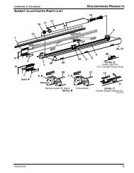
<strong>052930E</strong>-002<strong>Carefree</strong> ONE-<strong>Touch</strong> AwningReview this diagram before precedingArm Motor AssemblyRoller AssemblyArm Collector AssemblyRafter assem-Roller assembly isPerpendicular to theArm assembliesRafter assemblyMotorized sideNon-Motorized sidePage 2
<strong>052930E</strong>-002Step Five:on the RV.Installing the Awning AssemblyA. When the awning assembly is installed on the RV itshould closely match (figure 4) showing the awning assemblyviewed from the motorized and <strong>non</strong>-motorized sides.Start by removing the large Phillips Screw assembly on theside <strong>of</strong> the motorized arm assembly and slide the adjustableleg out <strong>of</strong> the arm assembly (figure 5).B. Measure the distance between the bottom brackets andthe awning rail (figure 6).Measurementinfigure 6Table 1Use holenumberbelow toreinstalladjustableleg<strong>Carefree</strong> ONE-<strong>Touch</strong> AwningLength <strong>of</strong>adjustableleg76” 7 14.5”76” 2C. Adjust the motorized arm assembly to the proper lengthusing Table 1. Match the measurement taken in step 5B tothe appropriate numbered hole needed to reattach theadjustable leg.Awning Rail77” 378” 479” 580” 681” 7#5#4#3Bottom Bracket82” 883” 984” 10#285” 11hole #1Table 1center <strong>of</strong>pivot slotAdjustable Legfigure. 6Page 6
<strong>052930E</strong>-002D. Repeat steps 5A through 5C for adjusting the length <strong>of</strong>the <strong>non</strong>-motorized arm assembly.Note: Both the motorized and <strong>non</strong>-motorized armassemblies should use the same numbered hole forreattaching the adjustable legs.E. Now that the ONE-<strong>Touch</strong> awning is assembled andadjusted for the RV, use two helpers to lift the awning into avertical position so the roller assembly is at the top.Warning: Exercise caution when lifting and handlingthe awning assembly. Both arm assemblies must remainperpendicular to the roller assembly and parallel to eachother (see page 2). Failure to handle the awning arms inthis way will bend the drive shafts.Tip: Silicone spray lubricant applied to the awning railwill allow for easier installation during step 5F.F. Carefully slide the awning polyrod or the Alumaguarddrip rail into the awning rail as the helpers alternately guidethe front and rear arms (figure 7).G. Once the awning arms are aligned with the previouslyinstalled bottom brackets, snap the bottom portion <strong>of</strong> eachadjustable leg into its bottom bracket and allow the awningto lean away from the side <strong>of</strong> the RV.Step Six:<strong>Carefree</strong> ONE-<strong>Touch</strong> AwningInstall the Top BracketsA. Remove the plastic wrap from the motorized armassembly and position <strong>of</strong> upper bracket at the awning rail.The top bracket should straddle the awning rail and be positionedfully up against the bottom <strong>of</strong> the rail (figure 8).The brackets should be straight up and down (not angled)for proper operation. (See below for your style <strong>of</strong> bracket)Note: The distance between the centers <strong>of</strong> the topbrackets must be within ½" <strong>of</strong> the distance between thecenters <strong>of</strong> bottom brackets. Also the awning arms must beperpendicular to the awning roller assembly (see page 2).B. Secure the bracket into the ro<strong>of</strong> line using two,#14 x 3" lag screws.Tip: For best results, pre-drill the lag screw holeswith a 3/16” bit through the awning rail and slightly into thestructural support member. Inject silicone sealant into theholes before installing the lag screws.C. Repeat Steps 6A & 6B for the <strong>non</strong>-motorized arm.SINGLE PIECE BRACKETAwning Railmounted to RVbracket restsagainst the bottom<strong>of</strong> the awningfigure. 8position top bracketas shown and fastenfigure 7Insert canopy orAlumaguard intoawning rail.Position TopBracket up anddown as required.Pin should float inslot when awing isfully retracted.FOR MULTI-PIECE BRACKETSAdjustablePositionadjustable legsas required to ensurethe top bracketsinstall straight upand down, not an-RV wallPage 7
<strong>052930E</strong>-002<strong>Carefree</strong> ONE-<strong>Touch</strong> AwningREVIEW KEY ELECTRICAL COMPONENTS BEFORE PRECEDINGPower Control ModulePower Control SwitchOutletPlugWire JointPage 8
<strong>052930E</strong>-002Step Seven: Install the Power ControlModule and Power Control SwitchTip: For optimum performance, always ensureelectrical connections are clean, dry, and tight. When usingsolderless terminals or other methods <strong>of</strong> attaching orconnecting wires, it is recommended to use heat shrinktubing to reduce corrosion contamination and the possibility<strong>of</strong> corroded connections or an open circuit.A. Review the wiring diagram in page 8. Determine asuitable location to mount the power control module andpower control switch that will allow convenient wiring andsufficient view <strong>of</strong> the ONE-<strong>Touch</strong> Awning during operationwhile depressing the power switch. Typical locationsinclude: just inside the entry door, in an overhead cabinetnear the entry door, or in a protected exterior compartment.The switch assembly requires a rough cut-out opening thatmeasures, 1" H x 2-1/4" W.Note: A maximum <strong>of</strong> 18” <strong>of</strong> wire is available to connectthe power control module to the power control switch.Consider the placement <strong>of</strong> the power control switch whileevaluating power control module placement.Caution: Minimum wire length and maximum wire sizeshould be selected to assure adequate voltage to theONE-<strong>Touch</strong> Awning motor.power control module. Use two <strong>of</strong> the wire joints provided toconnect one lead <strong>of</strong> the 15 amp fuse holder to the wire fromthe distribution panel and the other fuse lead to the positivewire (red) running from the three pronged connector.G. Connect the unattached end <strong>of</strong> the black wire runningfrom the wire joint shared with two other black wires to asuitable grounding locating on the RV. Use extra wires anda wire joint if necessary.Note: A suitable ground would be the chassis <strong>of</strong> theRV or any other conductive structure attached to thechassis.Step Eight:Mount the OutletA. Mark and drill a 15/16" hole in the exterior side wall,3” - 5” below the slot in the awning rail and 1” - 4” to the left<strong>of</strong> the front arm <strong>of</strong> the awning (figure 9).Awning Rail<strong>Carefree</strong> ONE-<strong>Touch</strong> AwningWarning (1) The power switch is factory installed on amounting plate beside a removable key switch; do notinstall the mounting plate in a location that will allow the keyto be bumped into. Bumping into the key may cause minorinjury or damage to the key.Warning (2) Do not mount the control box or relaynear heat producing elements such as LP appliances orengineexhaust components.within 5”3”within 4”1Top RafterBracketB. Once the location <strong>of</strong> the Power Control Module isdetermined fasten the control module in place using thescrews provided.C. After the location <strong>of</strong> the Power Control Switch is determined,cut out an opening in the mounting surface thatmeasures, 1" H x 2-1/4" W. Run the wires connected to thePower Control Switch through the opening. Do not fastenthe Power Control Switch in place at this time.E. Plug the three pronged connector at the end <strong>of</strong> the wiresrunning from the power switch into the three pronged outletin the power control module.F. Run a 14-guage minimum (10 or 12 gauge preferred)wire from the positive terminal on the RV, power distributionpanel (auxiliary battery circuit) to the positive wire (red)drill 15/16” holefigure. 9Tip: Use a sharp, 15/16" hole saw when drilling throughlaminate siding. A dull saw may result in an oversized holeor chipping and could allow potential moister damage. Forbest results, try a few sample holes in similar scrap material.Caution: Measure and mark carefully. Be aware <strong>of</strong>interior cabinet framing or other structures that may belocated directly behind the wall. Shift the position asnecessary while staying within the specified parameters. Beaware that structural obstructions may prevent proper holedrilling.Page 9
<strong>052930E</strong>-002B. Route two, 14-gauge wires from the power control moduleup to and through the hole in the side wall <strong>of</strong> the RV.Use the wire joints provided to connect the two, 14-guagewires to the two leads on the two pronged connector. Plugthe two pronged connector into the two pronged outlet inthe power control module.Tip: Conceal the two, 14 guage wires behind corner trimmolding or inside cabinets. If surface wiring is the onlyoption, obtain aftermarket concealment raceways to safelyroute the wires.C. Connect the wires running from the two prongedconnector to the terminals at the rear <strong>of</strong> the outlet using thespade connectors provided.D. Apply silicon sealant or putty tape to the back <strong>of</strong> theflange and place the outlet in the hole with the tab slots atthe 12 o’clock and 3 o’clock positions. Mount the outlet tothe side <strong>of</strong> the RV using the screws provided. Carefullytrim excess sealant from around the outlet. After installationthe rubber cover may also be removed if desiredE. Plug the electrical harness from the front arm assemblyinto the outlet on the side <strong>of</strong> the RV.Note: Align the tabs on the plug with the slots in thereceptacle, (at the 12 o’clock and 3 o’clock positions), insertthe plug fully and twist 1/8th <strong>of</strong> a turn clockwise untilthe metallic clip firmly latches in place. To disconnect, pullback on the metallic clip with your thumb while twisting theplug counter-clockwise 1/8th <strong>of</strong> a turn. Pull the plug straightout <strong>of</strong> the outlet.Tip: Allow a downward loop to form in the harness out<strong>of</strong> the outlet to prevent rainwater from entering the plug.Gas ShockSet CollarUpper Carriage<strong>Carefree</strong> ONE-<strong>Touch</strong> AwningTractioner is installed in step 10b.(2) If the motor runs in the reverse direction, it willbe necessary to push the switch out <strong>of</strong> the Power ControlSwitch panel, flip it upside down and reinstall.(3) The Power Control Switch panel may now bemounted in place.C. Have available the 9/64 hex wrench provided. Retractthe awning until the roller assembly makes onecomplete turn. While holding on to the Lower Carriage onthe motorized arm assembly, cut and remove the cable tieattaching the Upper Carriage and Lower Carriage together.Move the Lower Carriage up until it touches theUpper Carriage (figure 9). Tighten the clamping screws onthe Lower Carriage with the 9/64 hex wrench. Repeat thisprocedure on the <strong>non</strong>-motorized arm assembly.D. Extend the awning until the rafters are at the maximumopen position allowed by the Rafter Elbow Stop (figure 10).The Gas Shocks on both the armassemblies should be compressed 1/4” - 3/4” at this time.Jog the power switch slightly to retract and tighten thecanopy fabric.Step Nine:Verify Operationadjust LowerCarriageA. Extend awning completely out. If awning will not extendfully adjust both rafters “longer” by removing the screws(figure 10a) and increasing length <strong>of</strong> both ends <strong>of</strong> the raftersthe same amount. If canopy extends but rafter does notlock out (figure 10) then “shorten” the rafter so the “elbowstop” completely locks out against the rafter “inner channel“.figure 9Note: Webbing notRafter Inner ChannelB. Extend the awning until the roller assembly stopsturning. At this point the fabric will be slightly slack. Theawning should deploy evenly; refer to the troubleshootingguide if it does not.Note: (1) For Alumaguard models it may be necessaryto assist the deployment <strong>of</strong> the awning away from the RV forsteps 9A through 9F. Until the AlumaguardPage 10Rafter Outer ChannelOuter Bumper Stopfigure 10Elbow Stop
<strong>052930E</strong>-002E. Move the Set Collar on the motorized arm assembly upuntil it touches the base <strong>of</strong> the gas shock and tighten theclamping screws with the 9/64 hex wrench. Repeat thisprocedure on the <strong>non</strong>-motorized arm assembly. (figure 9).F. Cycle the awning in and out several times, (see theOperating Instructionsin the next section), tobe sure that it operatessmoothly and theAdjustable Rafterroller assembly is extendingevenly awayfrom the arm assemblies.Verify the raf-Adjustment Screwsters are unfoldingproperly and restingagainst the elbowstops when the awningis fully extended(figure 10). Refer tothetroubleshooting guideif rafter operationdoes not appearcorrect.<strong>Carefree</strong> ONE-<strong>Touch</strong> AwningAlumaguard awnings only, require that you installAlumaguard Tractioner on each end <strong>of</strong> the rollerassembly (fig 12).A. Grasp the Alumaguard Tractioner and O-Ring (shownin figure 12a) and disconnect one end <strong>of</strong> the O-Ring fromthe keeper on the Tractioner.B. Fully retract the awning and then extend it just enoughto take tension <strong>of</strong>f <strong>of</strong> the alumaguard wrap.(approximately 1/8 <strong>of</strong> a turn) Wrap the tractioner aroundthe roller tube and re-connect the O-ring to the keeper.C. Position the tractioner as shown in figure 12b and 12c.D. Extend the awning and verify that the AlumaguardTractioners are engaging the Alumaguard properly. Whenoperating properly, the Alumaguard Tractioner will engagethe end <strong>of</strong> the Alumaguard cover and move it upand over the roller assembly. If required, reposition tractionertoO-RingAdjustmentStickersfigure. 10aStep Ten: Securing the Canopy,Installing Tractioners and Safety StopsA. Secure the canopy fabric or Alumaguard using one,#6 x 3/8" hex head screw at the front and back end <strong>of</strong> theawning (fig 11). For vinyl (<strong>non</strong> alumaguard) awnings placescrews through awning rail, polyrod and canopyapproximately 1” in from each end <strong>of</strong> the fabric.For alumaguard place screws just outside the edge <strong>of</strong> thealumaguard to prevent it from shifting.FabricFigure 12aAwningRolled UpAlumaguardTractionerAlumaguardAlumaguard Tractioner#6 x 3/8" screw1/4”figure 12bfigure. 11Alumaguard(See Figure 12c on next page)Page 11
<strong>052930E</strong>-002<strong>Carefree</strong> ONE-<strong>Touch</strong> AwningEnd Capfigure 12cBottom Bracket Safety StopsNote:The Arm Assemblyis not shown forclarity.figure 13Alumaguard TractionerFabricAlumaguardA. Once installed the ONE-<strong>Touch</strong> arms must not beremoved from the bottom brackets (NO CARPORTPOSITION). To ensure the arms are not removed thequick install/release catch on the bottom bracketsmust be disabled by installing the Bottom BracketSafety Stops (figure 13, right).Section TwoWarning: If the awning is partially deployed the awningwill not be resistant to wind; partial extension is recommendedin calm conditions only. Additionally, Do not extendthe awning in gusty wind conditions. If the awning is to beleft unattended or used in breezy wind conditions it ishighly recommended that the roller assemblyTie-Downs provided be used at each end <strong>of</strong> the rollerassembly.STEP ELEVEN:Installing Protective PadRetract awning until the rafter rubber bumper nearlymakes contact with the sidewall. Stick the round clearprotective pad on the sidewall <strong>of</strong> the vehicle at the pointwhere the bumper will make contact once the awning iscompletely retracted.Operational InstructionsPower SwitchNote: The RV must be positioned relatively level for the<strong>Carefree</strong> ONE-<strong>Touch</strong> awning to operate properly.Tip: For optimum performance, be sure the batterysystems are fully charged or the power converterenergized.How the Power Control Module WorksKeyfigure 14To prevent damage to the ONE -<strong>Touch</strong> motor and circuitry,the Power Control Module monitors the current drawn bythe motor. If the current draw exceeds the preset factorylevel, the power control module shuts <strong>of</strong>f the power to theawning momentarily. This will occur if the power switchcontinues to be operated after the awning is fully retractedor extended. To reduce ware on the awning and it’s powersystem do not continuing to operate the power switch afterfull extension or retraction.Page 12
<strong>052930E</strong>-002Step One: To Extend or Retract the AwningA. To Extend: With the key in the “ON”, position, operatethe power switch in the “EXTEND” mode. Extend the awninguntil the roller assembly stops turning. At this point thefabric will be slightly slack.Jog the “RETRACT” switch slightly to tighten canopy.Note: If the awning is only to be partially extended,simply release the momentary rocker switch when theawning is extended to the point desired.B. To Retract: Operate the power switch in the“RETRACT” position until the awning is fully retracted.<strong>Carefree</strong> ONE-<strong>Touch</strong> AwningEmergency Retraction <strong>of</strong> AwningIf an alternative 12 volt power source is available:If power from the RV is unavailable for operation, the<strong>Carefree</strong> ONE-<strong>Touch</strong> awning can be safely retracted bydisconnecting the power plug and applying a positive andnegative 12-volts to the two terminals located on the bottomside <strong>of</strong> the motor housing.Using the jumper cables provided attach a jumper lead toone <strong>of</strong> the terminals and touch the opposite lead to theother terminal. If the awning does not retract reverse theleads.Caution: Be careful when retracting the awning in thismanner as the awning may move abruptly; it will benecessary to maintain contact with each <strong>of</strong> the two screwterminals throughout the retraction process.TerminalsIf no alternative 12 volt power source is available:If power from the RV is unavailable for operation and noalternative 12 Volt power source is available,the <strong>Carefree</strong> ONE-<strong>Touch</strong> awning can be safely retracted bydisconnecting the power plug and using a reversible electricdrill fitted with the straight 9/64 hex key provided to turnthe motor.The portion <strong>of</strong> the motor that can be turned isaccessible though an opening at the base <strong>of</strong> the motorhousing.Caution: Operate the drill in reverse at a low powersetting to retract the awning. It will be necessary to turn themotor with the drill throughout the retraction process.Page 13
<strong>052930E</strong>-002 <strong>Carefree</strong> ONE-<strong>Touch</strong> AwningWiring DiagramLNYellowWhiteBlueRedBlackPage 14
<strong>052930E</strong>-002Section Three<strong>Carefree</strong> ONE-<strong>Touch</strong> AwningTroubleshootingPRODUCT:<strong>Carefree</strong> ONE-<strong>Touch</strong> Patio AwningTITLE: ONE-<strong>Touch</strong> Awning TroubleshootingDOCUMENT: TS10017 - 11/01/99ONE-<strong>Touch</strong> AWNING TROUBLESHOOTING GUIDEPLEASE REVIEW THE FOLLOWING TO OBTAIN INFORMATION REGARDING SYMPTOMS, POSSIBLE CAUSESAND SOLUTIONS TO ONE-<strong>Touch</strong> AWNING PROBLEMS.SYMPTOM: The Rafter Arm will not extend to It’s complete extended position? POSSIBLE CAUSE (1): The upper carriage isimproperly adjusted causing the Gas Shock to engageprematurely.PROBABLE SOLUTION (1): Push the Extend♦Button on the Switch Panel and completely extendawning. Loosen the 9/64” Hex Head screws on the LowerCarriage as shown below. Move the Carriage down 8”to 10” and snug the screws up so the Carriage won’t falldown into the arm. Push the Retract Button on the PowerSwitch panel and retract the awning one revolution. MoveLower Carriage up until it touches the bottom <strong>of</strong> the TopCarriage. Re-tighten Clamping Screws with 9/64” hexwrench. (see below)Rafter Completely ExtendedTop Section <strong>of</strong> Raftershould contact the ElbowStop when Awning iscompletely extended.? POSSIBLE CAUSE (2): Awning is out <strong>of</strong> time.PROBABLE SOLUTION (2) Retime awning♦following timing instructions shown in Step 4, Page 4 <strong>of</strong>this Owners Manual.Adjust Set Collar until its up it isagainst the body <strong>of</strong> the shockInside <strong>of</strong> ArmGas ShockUpper CarriagePage 14• To release Carriage, loosen screwshere. be careful not to allow Carriage toslide down the Arm Channel.• Adjust Lower Carriage until it touchesthe bottom <strong>of</strong> the Upper Carriage.• Re-tighten screws.
<strong>052930E</strong>-002SYMPTOM: One side lifts higher or sooner than the other.? POSSIBLE CAUSE (1): The awning is out <strong>of</strong> time.PROBABLE SOLUTION (1): Retime awning♦following timing instructions shown in Step Four, Page Four<strong>of</strong> this Owners Manual.? POSSIBLE CAUSE (2): Strap or straps are loosewhen the awning is in the retracted position.PROBABLY SOLUTION (2): When the awning iscompletely retracted, check nylon strap inside <strong>of</strong> arm channeland see if it is loose. If loose, extend awning one revolution.Remove end cap screws and slide the drive wheel <strong>of</strong>the arm assembly out <strong>of</strong> the roller tube. Rotate drive wheel1/3 <strong>of</strong> a turn until the strap is tight. Repeat on opposite end.See Step Four, Page four <strong>of</strong> this OwnersManual for more detail.One Inner Arm liftshigher or sooner thanthe otherSYMPTOM: Awning Does Not Extend? POSSIBLE CAUSE (1): Key switch in the “OFF”? position♦PROBABLE SOLUTION (1): Position Key to “ON”? POSSIBLE CAUSE (2): Low battery♦PROBABLE SOLUTION (2): Charge battery? POSSIBLE CAUSE (3): Blown Fuse between the PowerControl Module and the Power Supply.♦PROBABLE SOLUTION (3): Replace fuse? POSSIBLE CAUSE (4): Battery disconnect circuits open♦PROBABLE SOLUTION (4): Close battery disconnectcircuits? POSSIBLE CAUSE (5): Incorrect wire connection, badconnections or bad grounds.♦PROBABLE SOLUTION (5): Refer to wiring diagram forcorrect connections. Check all wiring connections and groundsand make sure there is good contact. Repair as necessary.
<strong>052930E</strong>-002<strong>Carefree</strong> ONE-<strong>Touch</strong> Awning? POSSIBLE CAUSE (6): No power to the motor.♦ PROBABLE SOLUTION (6): Check for 12 volts at motor coverterminals, when switch is on. If there is no power there, check all wiringconnections and grounds and make sure there is good contact. Repair asnecessary.? POSSIBLE CAUSE (7): Faulty component in the awning.Disconnectfrom wall here♦ PROBABLE SOLUTION (7): Disconnect the power plug at the RV wall.Using jumper cables provided connect a 12VDC source directly to the terminals atthe motor cover. If this fails to operate the awning then there is a faultycomponent. At this point contact <strong>Carefree</strong>.SYMPTOM: The Roller Assembly spins but will not extend away from the RV.? POSSIBLE CAUSE (1): RV is not level.♦ PROBABLE SOLUTION (1): Level the RV.? POSSIBLE CAUSE (2): The center <strong>of</strong> the RollerAssembly is not at the same height as the center <strong>of</strong> theAwing Rail.♦ PROBABLE SOLUTION (2): Move the adjustable leg atthe base <strong>of</strong> the Arm Assembly so that the center <strong>of</strong> the RollerAssembly is closer to the same height as the center <strong>of</strong> the rail.? POSSIBLE CAUSE (3): Roller is higher on one side than itis the other♦ PROBABLE SOLUTION (3): Measure both ArmAssemblies and adjust stop bolts accordingly until the RollerAssembly is centered on the Awning Rail on both ends. (Both sidesmust be measured because it is possible that the relationshipbetween the Awning Rail and the center <strong>of</strong> the Bottom Bracket willvary from one arm to the other).? POSSIBLE CAUSE (4): If an Alumaguard Awning, thetraction masters may not be installed or are not installedcorrectly.♦ PROBABLE SOLUTION (4): Install or adjust tractionmaster as shown on page 11 <strong>of</strong> this manual .Unscrew PhillipsScrew AssemblyGrasp Adjustable leg here andadjust lower arm up or down (asshown to the right)until center <strong>of</strong> roller tube is closerin height to the center <strong>of</strong> theAwing rail.Page 16
<strong>052930E</strong>-002<strong>Carefree</strong> ONE-<strong>Touch</strong> AwningD. Conditions that are not related to the material or workmanship<strong>of</strong> the product: including any failure that resultsfrom an accident, wind, rain, water pooling, or other acts <strong>of</strong>God; purchaser’s abuse; neglect; failure to operate, or useor maintain the product in accordance with the instructionsprovided in the Owner’s Manual supplied with the product;(failure to operate the product(s) in accordance withinstructions in the Owner’s Manual and on the product shallalso include the removal or alteration <strong>of</strong> any productcomponent or device. In the event <strong>of</strong> any such removal oralteration, this warranty is void);E. ANY INCIDENTAL, INDIRECT, OR CONSEQUENTIALLOSS, DAMAGE, OR EXPENSE THAT MAY RESULTFROM ANY DEFECT, FAILURE, OR MALFUNCTION OFTHE CAREFREE OF COLORADO PRODUCT. Somestates do not allow the exclusion or limitation on incidentalor consequential damages, so the above limitation or exclusionmay not apply to you.F. Any failure that results from the use <strong>of</strong> another productwith a Warrantor’s product thatis not specifically approved by the Warrantor.7. RESPONSIBILITIES OF WARRANTOR UNDER THISWARRANTY: Repair or replace at Warrantor’s option, <strong>of</strong>the covered part(s) which Warrantor, in the exercise <strong>of</strong> itsreasonable discretion, determines to be defective; providedthat the Warrantor receives notice <strong>of</strong> the defect within thestated warranty period for that respective product/component. Warrantor will also pay the respective servicingdealer or agent for performing any repairs authorized byWarrantor as per the terms <strong>of</strong> this warranty.8. RESPONSIBILITIES OF ORIGINAL PURCHASER UN-DER THIS WARRANTY:E. Use reasonable care in the operation and maintenance<strong>of</strong> the products as described in the Owner’s Manual suppliedwith the product(s).9. WHEN WARRANTOR WILL PERFORM REPAIR ORREPLACEMENT UNDER WARRANTY.A. Repair or replacement will be scheduled and performedaccording to normal work flow at the nearest AuthorizedService Dealer, and depending on the availability<strong>of</strong>replacement parts.B. If the purchaser does not receive satisfactory resultsfrom the Authorized Service Dealer, the purchaser shouldcontact the <strong>Carefree</strong> <strong>of</strong> <strong>Colorado</strong> Customer ServiceDepartment (see paragraph 2).THIS WARRANTY GIVES YOU SPECIFIC LEGALRIGHTS AND YOU MAY ALSO HAVE OTHER RIGHTSWHICH VARY FROM STATE TO STATE. No action toenforce this warranty shall be commenced later than____30___ days expiration <strong>of</strong> the warranty period.The Duration <strong>of</strong> this Limited Warranty also limits theduration <strong>of</strong> any implied warranty such as warranty <strong>of</strong>merchantability or fitness for a particular use or purpose.Some states do not allow such limitations so the impliedwarranty limitation may not apply to you.<strong>Carefree</strong> <strong>of</strong> <strong>Colorado</strong> reserves the right to change thespecifications and design <strong>of</strong> any product without notice andwith no obligation to make corresponding changes toproducts previously manufactured.A. Retain dated Pro<strong>of</strong> <strong>of</strong> Purchase for specific product, andprovide it as requested.B. Inspect the awning upon purchase to confirm thecondition <strong>of</strong> the canopy and the proper operation <strong>of</strong> theproduct.C. Perform “Periodic Preventative Maintenance” as specifiedin Owners Manual.D. Deliver any product claimed or found defective duringwarranty period to the nearest <strong>Carefree</strong> <strong>of</strong> <strong>Colorado</strong>Authorized Service Dealer. The Original Purchaser isresponsible for any expenses related to delivery orpick up <strong>of</strong> product to/from the Service Dealer. Visitcarefree<strong>of</strong>colorado.com for the name <strong>of</strong> nearest AuthorizedService Dealer, or call <strong>Carefree</strong> at the phone number shownabove.Page 19
ONE-<strong>Touch</strong> 12Volt Patio Awning TroubleshootingONE-TOUCH PATIO AWNINGTROUBLE SHOOTING CHARTSTABLE OF CONTENTSPAGE NO.AWNING WON'T ROLL OUT/IN ELECTRICAL................................AWNING WON'T ROLL OUT/IN MECHANICAL..............................AWNING ROLLS IN OR OUT UNEVENLY.......................................RAFTER WILL NOT FULLY EXTEND...............................................AWNING RETRACTS MORE THAN 30 SECONDS..........................TOOLS NEEDED1. VOLT/OHM METER2. PHILIPS SCREWDRIVER3. 9/64" ALLEN WRENCH052958-00104JAN01TCT
ONE-<strong>Touch</strong> 12Volt Patio Awning TroubleshootingAWNING WON'T ROLL OUT/IN(ELECTRICAL)BATTERY MUST BE FULLYCHARGED AND THE RVLEVEL. POLARITY TOCONTROL MODULE MUST BECORRECT OR CIRCUIT WILLNOT WORK. (SEE FIGURE 1)IS THE SWITCH ON?YESNOTURNSWITCH ONCKECK FUSECHECK VOLTAGE AT MOTORCOVER TERMINALS(WITH METER).SEE AWNING WON'TROLL OUT(MECHANICAL)YESIS IT GREATER THAN 11.0VWHILE PUSHING EXTEND/RETRACT SWITCH?NOUNPLUG RAFTERHARNESS PLUG FROMOUTSIDE WALLRECEPTACLE ON RV.APPLY 12 VOLTSDIRECTLY TOTERMINALS ONMOTOR COVERYESDOES AWNING ROLLOUT/IN?NOSEE AWNING WON'TROLL OUT(MECHANICAL)APPLY 12V TORAFTER HARNESSPLUGYESDOES AWNING ROLLOUT/IN?NOCHECK CONNECTIONS INRAFTER PLUG HOUSING.REPAIR OR REPLACEHARNESSRECONNECT RAFTERHARNESS PLUG TO OUTSIDEWALL RECEPTACLE.DISCONNECT 2-PIN MOTORCONNECTOR FROM CONTROLMODULE AND APPLY 12VOLTS TO PINS ON PLUG.(SEE FIGURE 1)NODOES AWNING ROLLOUT/IN?YESCHECK WIRE FOR AT LEAST 14GAUGE. CHECK ALLCONNECTIONS FROM 2-PINMOTOR CONNECTOR TO OUTSIDERECEPTACLE. REPAIR ORREPLACE WIRE CONNECTIONSRECONNECT 2-PIN MOTOR CONNECTOR TOCONTROL MODULE. ADJUST CURRENT LIMITPOT TO UPPER LIMIT. (SEE FIGURE 1)DOES AWNING ROLLOUT/IN?NODISCONNECT 3-PIN CONNECTORFROM CONTROL MODULE.MEASURE FOR CONTINUITYBETWEEN BLACK AND BLUE WIREWHILE DEPRESSING EXTEN/RETRACT SWITCH IN EACHDIRECTION. (SEE FIGURE 1)FIGURE 1REPAIR OR REPLACESWITCH PANELNODOES METER READ 0 ohmsOR 470 ohms?YESRECONNECT 3-PIN CONNECTOR TO CONTROLMODULE. MEASURE VOLTAGE BETWEEN GND.AND +12VDC ON 3-PIN CONNECTOR OFCONTROL MODULE WHILE DEPRESSINGEXTEND/RETRACT SWITCH. SEE FIGURE 1052958-001REPLACE CONTROLMODULEYESIS VOLTAGE GREATERTHAN 11 VOLTS?NOINSPECT WIRING FOR AT LEAST 14 GAUGEFROM POWER SOURCE TO CONTROLMODULE. CHECK ALL CONNECTIONS FROMPOWER SOURCE TO CONTROL MODULE
ONE-<strong>Touch</strong> 12Volt Patio Awning TroubleshootingAWNING WON'T ROLL OUT(MECHANICAL)RV MUST BELEVELDOES ROLL BAR TURN?NOADJUST TRACTIONER TOENGAGE ALUMAGUARDYESUNPLUG RAFTER HARNESSFROM RECEPTACLE ON RV WALL.DRIVE AWNING FROM RV WITHDRILL MOTOR AND 9/64" HEX BITDOES AWNING ROLL OUT?NOYESDOES AWNING ROLL OUT?NOCHECK AND VERIFY THAT ROLLBAR CENTER AND AWNINGRAIL CENTER ARE AT THESAME HEIGHT. IF NOT ADJUSTSTOP BOLT ON ARMASSEMBLY.SEE "AWNING WON'T ROLL O UT/IN"ELECTRICALDOES AWNING ROLL OUT?NOREMOVE COTTER PIN FROMNON-MOTOR SIDE COVERVERIFY TIMING IS CORRECTAND THAT THE AWNINGLIFTS AT 2 REVOLUTIONSWHILE EXTENDING (BOTHENDS MUST MATCH)'A'REMOVE MOTOR COVER.DISCONNECT RAFTER HARNESSPLUG FROM RV WALL RECEPTACLE;DISCONNECT MOTOR LEADS FROMCOVER TERMINALS; CONNECT 12VTO MOTOR LEADSYESDOES AWNING ROLL OUT?NOCHECK MOTOR LEADS FORGOOD CONNECTIONS.REPLACE MOTORAWNING WON'T ROLL IN(MECHANICAL)RV MUST BELEVELLOOSEN LOWER CARRIAGESAND COLLARS ON SHOCKSYESDOES AWNING ROLL IN?NOADJUST RAFTER CARRIAGESAND COLLARS ON SHOCKS PERINSTRUCTIONSYESARE THE ARMS BENT?NODOES AWNING ROLL IN?NOREPLACE ARM ASSY.CHECK TIMING MEASUREDISTANCE FROM CENTEROF ROLL BAR TO BOTTOMBRACKET ON EACH ARM.ADJUST AS NECESSARYWITH ± 1/2"YESIS DRIVE SHAFT BENT?NONODOES AWNING ROLL IN?REPLACE DRIVE SHAFTIS THIS COMPETITORSROLL BAR?NOSEESEEREPLACE WITH CAREFREEROLL BARYES'A''A'052958-001
ONE-<strong>Touch</strong> 12Volt Patio Awning TroubleshootingAWNING ROLLS IN OR OUT UNEVENLY(MECHANICAL)(FOR ACRYLIC AWNINGS) ARETHE TRACTIONERS ENGAGINGTHE ALUMAGUARD AT BOTHENDS?NOADJUST BOTH TRACTIONERSTO ENGAGE ALUMAGUARDAND /OR ADJUST (RAISE ORLOWER) ONE STOP BOLT ONARMDOES AWNING ROLL IN OR OUTEVENLY?NOVERIFY BOTH BOTTOMBRACKETS ARE THE SAMEDISTANCE FROM AWNINGRAILDOES AWNING ROLL IN OR OUTEVENLY?NOADJUST TIMING SO BOTHARM CHANNELS RISE AFTER2ND REVOLUTION OF ROLLBARDOES AWNING ROLL IN OR OUTEVENLY?NOCHECK TIMING. MEASUREDISTANCE FROM CENTEROF ROLL BAR TO BOTTOMBRACKET ON EACH ARM.ADJUST AS NECESSARYWITH ± 1/2 "DOES AWNING ROLL IN OR OUTEVENLY?NOVERIFY THAT STRAP IS NOTTWISTED, IF IT IS TWISTEDREPAIR OR REPLACEDOES AWNING ROLL IN OR OUTEVENLY?NO052958-001
ONE-<strong>Touch</strong> 12Volt Patio Awning TroubleshootingRAFTER WILL NOT FULLY EXTEND(MECHANICAL)RAFTER LENGTH MUST BE EQUAL FROM PIVOTPOINT TO PIVOT POINT. RAFTER LENGTH MUST BE1/2 OF CANOPY EXTENSION ± 1"CHECK RAFTER LENGTHYESDOES RAFTER FULLY EXTEND?NOADJUST RAFTER CARRIAGES ANDSHOCK COLLARSLOOSEN LOWER CARRIAGES ANDSHOCK COLLARSDOES RAFTER FULLY EXTEND?NOVERIFY TIMING IS CORRECT AND THATTHE AWNING LIFTS AT 2 REVOLUTIONSWHILE EXTENDINGDOES RAFTER FULLY EXTEND?NOCHECK TIMING. MEASUREDISTANCE FROM CENTEROF ROLL BAR TO BOTTOMBRACKET ON EACH ARM.ADJUST AS NECESSARYWITH ± 1/2 "DOES RAFTER FULLY EXTEND?NOCHECK STRAP FOR TWISTING.REPAIR OR REPLACE052958-001
ONE-<strong>Touch</strong> 12Volt Patio Awning TroubleshootingAWNING RETRACTS MORE THAN 30SECONDS (ELECTRICAL)SEE AWNING WON'TROLL IN(MECHANICAL)YESCHECK VOLTAGE AT MOTORCOVER TERMINALS (WITHMETER) IS IT GREATER THAN11.0V WHILE PUSHING RETRACTBUTTON?NOCONTROL MODULEUNPLUG RAFTER HARNESSPLUG FROM WALLRECEPTACLE ON RV. APPLY 12VOLTS DIRECTLY TOTERMINALS ON MOTORCOVERYESDOES AWNING RETRACT MORETHAN 30 SECONDS?APPLY 12V TORAFTER HARNESSPLUGFIGURE 2YESDOES AWNING RETRACT MORETHAN 30 SECONDS?RECONNECT RAFTERHARNESS PLUG TO OUTSIDEWALL RECEPTACLE.DISCONNECT 2 PIN MOTORPLUG FROM CONTROLMODULE AND APPLY 12VOLTS TO PLUGYESDOES AWNING RETRACT MORETHAN 30 SECONDS?NORECONNECT 2 PIN CONNECTOR TOCONTROL MODULE. ADJUST CURRENT LIMITPOT TO UPPER LIMITCHECK WIRE FOR AT LEAST 14GAUGE. CHECK ALLCONNECTIONS FROM 2-PINCONNECTOR TO OUTSIDE WALLRECEPTACLE. REPAIR ORREPLACE WIRE CONNECTIONS'A'AWNING RETRACTS MORE THAN30 SECONDS (MECHANICAL)REMOVE MOTOR COVER.DISCONNECT RAFTERHARNESS PLUG FROM RVWALL RECEPTACLE;DISCONNECT MOTORLEADS FROM COVERTERMINALS; CONNECT12V TO MOTOR LEADSYESDOES AWNING RETRACT MORETHAN 30 SECONDS?NORV MUST BELEVELLOOSEN LOWER CARRIAGEAND SHOCK COLLARYESDOES AWNING RETRACT MORETHAN 30 SECONDS?CHECK MOTOR LEADS FORGOOD CONNECTIONS.REPLACE MOTORADJUST RAFTER CARRIAGEAND COLLAR ON SHOCK PERINSTRUCTIONSYESIS DRIVE SHAFT BENT?NOYESARE THE ARMS BENT?NOREPLACE DRIVE SHAFTDOES AWNING RETRACT MORETHAN 30 SECONDS?YESIS THIS AN A&EROLLBAR ?NOSEEREPLACE ARM ASSY.CHECK TIMING.MEASURE DISTANCEFROM CENTER OFROLL BAR TO BOTTOMBRACKET ON EACHARM. ADJUST ASNECESSARYYESREPLACE WITH CAREFREEROLL BAR'A'DOES AWNING RETRACT MORETHAN 30 SECONDS?NOSEE'A'052958-001