INSTALLATION MANUAL - Carefree of Colorado
INSTALLATION MANUAL - Carefree of Colorado
INSTALLATION MANUAL - Carefree of Colorado

You also want an ePaper? Increase the reach of your titles
YUMPU automatically turns print PDFs into web optimized ePapers that Google loves.
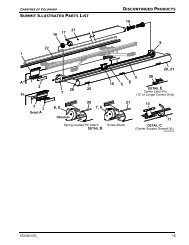
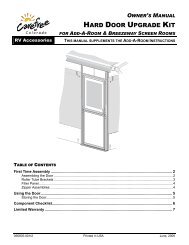
<strong>Carefree</strong> <strong>of</strong> <strong>Colorado</strong> Installation Manual APEX ITEM DESCRIPTION QTY NOTE 1 Apex Awning Assembly 1 1 2 Mounting Bracket (Note) 2 3 Screw, Rolock, Thread Cutting 3/8 x 1 1/2 (Note) 3 4 Screw, Lag 3/8 x 3 (Note) 3 5 Screw, Hex Head 5/16-18 x 1 1/2 (Note) 3 6 Square Nut 5/16-18 (Note) 3 7 Hex Key 7mm x 133mm 1 8 Control Box Single Awning 1 4 9 Key Pad Assy Single Awning 1 4,5 10 Remote Control Key FOB, 433MHz Single Awning 1 6 11 Control Box Dual Awning 1 4 12 Key Pad Dual Awning 1 4,5 13 Remote w/ stop, 433 MHz Dual Awning 1 4,6 14 Control Box 1 (Motor #1, Motor #2) 4-Awning Combo 1 4 15 Control Box 2 (Motor #3, Motor #4) 4-Awning Combo 1 4 16 Key Pad 4-Awning Combo 1 4,5 17 Remote w/ stop, 433 MHz 4-Awning Combo 1 4,6 18 RF Receiver, 433 MHz 1 19 RJ11 Cable 60 inches 1 7 20 RJ11 Cable 240 inches 1 9 21 Sensor, Ignition Lock-Out 1 7,8 22 Splitter 1 7,8 23 Coupler, Cable 1 9Notes: 1. Awning configuration is specified at time <strong>of</strong> order, including awning length, LH or RHconfiguration, fabric color etc. Check awning assembly against original purchase order.2. Item 2 Mounting Plates: Quantity <strong>of</strong> 3 per awning 18' or lessQuantity <strong>of</strong> 4 per awning 19' or longerSome Original Equipment Manufacturer (OEM) installations may specify a different quantity.3. Mounting screws (item 3 or 4) for the mounting plates = 6 per mounting plateSecuring screw (item 5) and nut (item 6) = 1 each per mounting plate. See note 2.4. Electronic components are not interchangeable between systems.5. Mounting screws are included with switches and mounting plates.6. Additional remotes can be ordered separately.7. 60" cable (item 19) is furnished with items 9a, 18 and 21, one additional cable is furnishedwith the 4-awning control boxes (items 14, 15).8. The optional ignition lockout and splitter (items 21, 22) must be ordered separately. Twoversions <strong>of</strong> the lockout sensor are available, refer to page 10 for description.9. Long cable (item 20) and /or coupler (item 23) are specified at time <strong>of</strong> order.522522-002r4 3
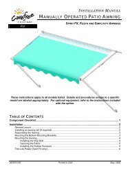
<strong>Carefree</strong> <strong>of</strong> <strong>Colorado</strong> Installation Manual APEX1. Determine the location <strong>of</strong> the awning mounts:1.1 Mounting area must be flat and clear <strong>of</strong> obstacles,1.2 The awnings have appreciable weight; the mounting screws MUST fasten into the structure.2. (Refer to Figure 3) Position the mounting plates on the coach ro<strong>of</strong>. Horizontally position the platesusing the dimension in the chart.NOTE: Two types <strong>of</strong> attaching screws are included in the kit. The 3/8” rolock screws are forattaching into metal structure. The 1/4” lag screws should be used for attaching into woodstructures.3. For rolock thread cutting screws:3.1 For each plate, on one end <strong>of</strong> the plate, use the plate as a template and drill an 11/32” pilot holeinto the structure. Attach the plate using a 3/8-16 x 1 1/2 thread cutting screw.3.2 Confirm position <strong>of</strong> plate and repeat step 6 on the opposite end <strong>of</strong> the mounting plate.3.3 Continue to drill and attach using the 3/8-16 x 1 1/2 thread cutting screws. Use six (6) screwsminimum per plate.4. For lag screws:4.1 For each plate, on one end <strong>of</strong> the plate, use the plate as a template and drill a 3/16” pilot holeinto the structure. Attach the plate using a 3/8 x 3 lag screw.4.2 Confirm position <strong>of</strong> plate and repeat step 6 on the opposite end <strong>of</strong> the mounting plate.4.3 Continue to drill and attach using the 3/8 x 3 lag screws. Use six (6) screws minimum per plate.5. In the rear track <strong>of</strong> each mounting plate, start one (1) 5/16-18 x 1 1/2 screw and square nut through hole inback <strong>of</strong> mounting plate. Do not tighten at this time.6. At the motor location, drill one (1) 1/2” hole through outer surface. The position may be under or behind theend cap position.MOUNTING THE AWNING UNITSecuring BoltAwning Frame (ref)MountingBracket (ref)Figure 2. Mounting the Awning.1. While lifting the awning, route the awning motor wires through the 1/2” hole drilled previously.NOTE: It is necessary to first insert the sensor cable and connector through the hole theninsert the motor wires.2. Set the awning into the hooks <strong>of</strong> the mounting bracket. Pull the case forward to fully engage thebracket.3. Adjust the horizontal position <strong>of</strong> the awning as required.4. Tighten the securing bolts. Torque to 10 ft-lbs.5. Seal the wires and access hole with a quality silicone sealant.522522-002r4 5RTA004
APEX Installation Manual <strong>Carefree</strong> <strong>of</strong> <strong>Colorado</strong><strong>INSTALLATION</strong> – ELECTRICALWARNINGALWAYS DISCONNECT THE VEHICLE BATTERY AND ELECTRICAL SOURCES BEFORE WORKING WITH ELECTRICALWIRING AND COMPONENTS.IMPORTANT NOTICES: Failure to follow the wiring instructions in this publication may void the warranty. All wiring must conform to NEC (National Electrical Code) and local codes. DO NOT wire two or more motors to one motor controller.The SO cable from the 110VAC awning motor can only pass directly through a wall, it can not belaid up in the wall and must be connected to NM wire or individual wires in conduit no more than6 inches past the point <strong>of</strong> entry.The installer must provide enclosed junction boxes for all 110VAC wire splices. Boxes arerequired in conformance with prevailing construction codes. Installers are required to furnishthe UL approved electrical boxes where required.At the control box location, AC input is required. It is recommended that the installer provide adedicated AC circuit for the awning system that is protected by an appropriate sized fuse/circuitbreaker. Each patio awning draws a maximum <strong>of</strong> 3 amps.The motion sensor for the Direct Response system is mounted on the patio awning. 10 feet cable isavailable from the awning wall mount, and will require a routing path to the control box. If the controlbox is located at a distance greater than 10 feet, the installer must provide a terminated jumper cablefrom the box location to the cable end.Terminated cable is a 4-wire RJ11 terminated phone cord (straight, notwist).NOTE: Cable lengths <strong>of</strong> the furnished cables are listed in the chart withthe system wiring diagram. If a connection requires a lengthgreater than the supplied cable, the installer must provide aterminated jumper cable from the box location to the cable end.Terminated cables are 4-wire RJ11 terminated phone cord(straight, no twist).GreenBlackRedGreenRedBlackYellowYellowCables are 4-wire RJ11terminated phone cord(straight, no twist).RTA0316 052522-002r4
<strong>Carefree</strong> <strong>of</strong> <strong>Colorado</strong> Installation Manual APEXCOMPONENT <strong>INSTALLATION</strong>Control Panel Installation - Key Pad1. Locate the mounting location <strong>of</strong> the key pad. The key padrequires a flat area approximately 2 3/4" wide by 4 1/2" tall.2. Use the mounting plate as a template and mark the location<strong>of</strong> the two mounting holes.3. Remove the plate, mark and cut a 1" hole in the positionshown.4. Mount the plate to the surface using the included screws.5. Route the 25 foot RJ11 cable from the control box locationthrough the wall and mounting plate.6. Attach the cable to the back <strong>of</strong> the key pad then attach thekey pad to the mounting plate.NOTE: The key pad attaches to the plate with magneticlatches. No additional attaching hardware isrequired.Key Pad4.5”2.75”3.25”(ref)RJ11 CableMounting PlateO 1” min.O .125” Pilot Hole(2 plcs)1.25”Figure 3. Multiple Awning Key Pad.Paramount005Control Box InstallationNOTES:a) For Multiple Awing Installations: The awning motor that is connected to the controller board marked"motor #1" will correspond with "Awning 1" on the touch pad control and remote. The awning motorconnected to "motor #2" will correspond with "Awning 2" on the controls etc.b) For 4-Awning Installations: Awnings connected to motor #1 & #2 correspond to "Passenger SideAwnings", awnings connected to motor #3 & #4 correspond to "Driver Side Awnings".c) The control boxes are not suitable for exterior installations and must be mounted in the INTERIOR<strong>of</strong> the vehicle.For Single Awning installations: refer to wiring diagram on page 11.For 2-Awning installations: refer to wiring diagram on page 12.For 4-Awning installations: refer to wiring diagram on page 14.522522-002r4 7
APEX Installation Manual <strong>Carefree</strong> <strong>of</strong> <strong>Colorado</strong>1. Locate the mounting location <strong>of</strong> the control box(es). Each box requires a flat area approximately 6 1/2"x 6 1/2" with a clearance depth <strong>of</strong> 2 3/8".For 4 awning installations: A 60" jumper cable is used #8 x 3/4 Screw (2)between the two control boxes. This allowsapproximately 55" <strong>of</strong> cable between the boxes.Position the boxes to allow the jumper to be connectedand routed with some slack in the cable.2. Remove the lid. Attach the box to the mounting surfaceusing a minimum <strong>of</strong> two (2) #8 x 3/4 screws each. Thescrews must be mounted in opposite corners.3. Route a 2-conductor 14AWG NM wire w/ groundfrom the AC power source to the box. It isrecommended that the installer provide a dedicatedAC circuit that is protected by an appropriate sizedFigure 4. Control Box.fuse/circuit breaker. Each patio awning draws amaximum <strong>of</strong> 3 amps.NOTE: Each board must have a 110VAC supply. The diagram shows a separate power source foreach box; each power source is spliced with wire nuts to power both boards in a box.4. Connect the wires to the control box circuit boards as shown in the wiring diagram (Detail A).5. Route the motor wires from awning #1 to controller #1 (motor#1); attach the wires to the terminals as shown.NOTE: For LH motor configurations:RED WIRE goes to terminal (1); BLACK WIRE goes to terminal (2).For RH motor configurations:RED WIRE goes to terminal (2): BLACK WIRE goes to terminal (1).6. Attach the RJ11 cable from the sensor <strong>of</strong> awning #1 to the "AMD" receptacle <strong>of</strong> controller #1.7. Repeat step 5 and 6 for the other awnings.8. After testing connections, use Loctite 29005 or equivalent to secure screws in terminal block.9. Attach the remaining RJ11 cables as shown in the wiring diagram. Use the slot cutouts in the box toroute the phone cables.NOTE: The key pad and RF receiver only attach to controller #1.2 3/8”6 1/2”(typ)RTA019c8 052522-002r4
<strong>Carefree</strong> <strong>of</strong> <strong>Colorado</strong> Installation Manual APEXInstalling the Remote Receiver1. Determine the location <strong>of</strong> the RF receiver:1.1 Do not mount the unit near heat producing elementssuch as LP appliances or engine exhaustcomponents.1.2 For best reception, do not mount the unit near or ona metal surface.1.3 Mount the unit with the antenna pointing up.1.4 The included cable is approximately 60 inches long.Mount the unit close enough to the splitter or controlbox so that the cord can be connected withoutstressing the connections.1.5 Allow adequate room below the box to access the connector jack, programming button andindicator light.2. Position the control box and secure using two (2) #6 x 1/2” screws.NOTE: If the box is mounted on a surface that is less that 1/2” thick, the screws will protrudethrough the opposite side <strong>of</strong> the surface.3. Connect the cable to the receiver.4. Route the cable to the splitter; or, to the control box and connect to “EYE”.PROGRAMMING THE REMOTE RECEIVERThese instructions apply to the current 433 MHz configuration <strong>of</strong> the remote and receiver (RR version 2).For older versions refer to the Apex Service Manual listed on the inside <strong>of</strong> the front cover.1. Power to the control box must be on.2. Press and release the “Press to Learn Transmitter” button on the bottom <strong>of</strong> thereceiver box. The receiver is in program mode when the red light comes on.3. Press and release the stop button on the remote. The red light will go outafter the receiver learns the remote signal.NOTE: For single awning key FOB remotes: Pressing the stopbutton will cause the blue up arrow button to default as theopen (extend) function. If a function button is pressed totrain the receiver, it will be programmed as the open (extend)button. Example: Pressing the bottom button will programthe bottom button for extend and the top button as retract.4. Repeat for each additional remote.OPERATIONAL NOTES: Transmitter and receiver operate on a frequency <strong>of</strong> 433 MHz. The receiver exits the program mode after ten seconds.#6 x 1/2Screw (2) If the light does not come on above, the memory is full and must be cleared. If the light still does not come on,check the continuity <strong>of</strong> the cord between the boxes and repair or replace as required. Pin 1 <strong>of</strong> the 1 st connectorgoes to pin 1 <strong>of</strong> the 2 nd connector etc. If the light does not go out in above, the receiver already knows the transmitter's signal or the battery in theremote needs to be replaced. To clear the memory: PRESS AND HOLD the transmitter learn button. While holding the button, the indicator lightshould be OFF for the full 5 seconds then come on. The system may be programmed for up to 5 remotes. Additional remotes may be ordered separately.TOEYE PORTon RP24ProgramModePress to LearnTransmitter3 7/8”Figure 5. RF Receiver.IndicatorLightTOEYE PORTon RP24ProgramModePress to LearnTransmitterUPUP4 3/16”1”RTA034ProgramButtonDR020522522-002r4 9
APEX Installation Manual <strong>Carefree</strong> <strong>of</strong> <strong>Colorado</strong>Ignition Lockout Sensor Installation (Optional)Two ignition lockout sensors are available with the Direct Response System. The STD ignition lockout module disables the extend function when the module receives a currentthrough a switched 12VDC circuit.. The RTL ignition lockout module will fully retract the awning and disable the extend function when themodule receives a current through a switched 12VDC circuit.A switched 12VDC source is a line that is "hot" when the ignition switch is in the on position; or, a 12VDCcircuit through a relay that is "hot" when a specific condition is met (i.e. releasing the parking brake).Relays are not furnished.1. Disconnect power to the awning. Shut <strong>of</strong>f the power source or pull the appropriate circuit breaker.2. Locate the control box for the Direct Response System.3. Open the cover <strong>of</strong> the control box.4. For Single Awning Applications:4.1. Disconnect the remote receiver cable from the "EYE" port in the control box. Do not disconnect thecable from the receiver box.4.2. Connect the supplied 6" cable to “EYE” port in the control box.4.3. Attach the splitter to the other end <strong>of</strong> the cable.4.4. Plug the cable from the remote receiver into the splitter.4.5. Attach the Lock-Out Sensor to the end <strong>of</strong> the 60" cable. Route the cable as desired and connectthe cable to the splitter.4.6. Proceed to step 6.5. For Multiple Awning Applications:5.1. The module may be connected to the control box as described for single awning applications.OR5.2. The module may be directly connected to any open "EYE" port on any <strong>of</strong> the control boards. It isnot necessary to use the short cable or splitter.5.3. Proceed to step 6.NOTE: Wires to the module are not pin specific.6. Attach one 18-gauge wire to a terminal <strong>of</strong> the sensor and route the wire to a suitable 12VDC ground.7. Attach a second 18-gauge wire to the second terminal <strong>of</strong> the sensor and route the wire to a SWITCHED12VDC source.8. Bundle and secure the sensor, cable and wires as required.9. Reattach the control box cover.10 052522-002r4
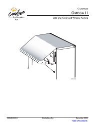
PowerOn/OffExtendStopRetractAuto-RetractOn/OffWind SpeedHighLow<strong>Carefree</strong> <strong>of</strong> <strong>Colorado</strong> Installation Manual APEXWIRING DIAGRAM – SINGLE AWNING3 Conductor 14AWGNM Wire w/ Gnd2 Conductor 14AWGNM Wire w/ Gnd3whtblkgrnTo 110VACNOTES:1 Wire Legend:REDBLKWHTGRN1234567REDBLKWHTGRNRedBlackWhiteGreen (Ground)AMDAUX SUNEYEDSKAwningSensor5Ignition Switched+12VDC12VDCGroundSensorRemoteKey PadSplitter12345674IgnitionLockoutSensor(Optional)TOEYE PORTon RP24ProgramModePress to LearnTransmitterRFReceiver2 For LH Motor Configurations:Motor Red goes to Pin (1); Motor Black goes to Pin (2)For RH Motor Configurations:Motor Red goes to Pin (2) Black; Motor Black goes to pin (1)3 The SO cable from the 110VAC awning motor can only pass through a wall, it cannot be laid up in the walland must be connected to NM wire or individual wires in conduit no more than 6 inches past the point <strong>of</strong> entry.45Detail AFor RH ConfigurationReverse Red & Black WiresSplitter is used only when Optional Lock-Out Sensor is installed. Connect RF Receiver directly to “EYE”if Lock-Out is not installed.Wires for the Ignition Lock-Out Sensor are not pin specific.whtblkgrnBLKREDWHTGRNUPKey PadRibbonCableWind SpeedRear ViewSwitch PanelDetail BUsed thru 2006PatioDR012FROM TO (RH CONFIGURATION) TO (LH CONFIGURATION)Motor Black Control Box 1 Control Box 2Red 2 1White 3 3Ground 6 6AC PowerSourceWhite Control Box 4 Control Box 4Black 5 5Ground 7 7Awning Sensor 10’ Cable Control Box “AMD” Control Box “AMD”Key Pad 60“ Cable Control Box “DSK” Control Box “DSK”Splitter 60" Cable Control Box "EYE" Control Box "EYE"RF Receiver 60” Cable Splitter SplitterIgnition Lockout 60“ Cable Splitter SplitterNotes: 1. Cable lengths are the lengths <strong>of</strong> the furnished cables. If a connection requires a length greater than the supplied cable, theinstaller must provide a terminated jumper cable from the box location to the cable end.522522-002r4 11
APEX Installation Manual <strong>Carefree</strong> <strong>of</strong> <strong>Colorado</strong>WIRING DIAGRAM – 2-AWNINGS3 Conductor 14AWGNM Wire w/ Gnd333 Conductor 14AWGNM Wire w/ GndREDBLKWHTGRN1234567REDBLKWHTGRNAMDAUX SUNEYEDSKAwning #1SensorREDAwning #2BLKWHTGRNSensor5Ignition Switched+12VDC12VDCGroundSensor #1RemoteKey PadIgnitionLockoutSensor(Optional)Splitter4TOEYE PORTon RP24ProgramModePress to LearnTransmitterRFReceiverUPKey PadAMDSensor #2BLKREDWHTGRN1234567AUX SUNEYEDSKWhtBlkGrn1234567GreenBlackRedGreenRedBlackYellow2 Conductor 14AWGNM Wire w/ GndTo 110VACWhtBlkGrn1234567DETAIL A110VAC Power Line InYellowCables are 4-wire RJ11terminated phone cord(straight, no twist).DR01412 052522-002r4
<strong>Carefree</strong> <strong>of</strong> <strong>Colorado</strong> Installation Manual APEXNOTES:1 Wire LegendRedBlackWhiteGreen (Ground)2345Awning #1shown as LH Motor, Awning #2shown as RH MotorFor LH Motor Configurations:Motor Red goes to Pin (1); Motor Black goes to Pin (2)For RH Motor Configurations:Motor Red goes to Pin (2); Motor Black goes to Pin (1)The SO cable from the 110VAC awning motor can only pass directly through a wall; it cannot be laid up in the walland must be connected to NM wire or individual wires in conduit no more than 6" past the point <strong>of</strong> entry.Splitter is used only when Optional Lock-Out Sensor is installed. Connect RF receiver directly to "EYE" ifLock-Out is not installed.Wires for Ignition Lock-Out Sensor are not pin specific.6 For screw type terminals: After testing connections, use Loctite 29005 or equivalentto secure screws in terminal block7 Cables are 4-wire RJ11 terminated phone cord (straight, no twist).8 Terminal block designations are for reference only. Actual boards may not be marked.Loctite29005Screw TypeTerminal BlockTO CONTROL BOARDFROM MOTOR #1 MOTOR #2AC Power Source White 4 4Black 5 5Ground 7 7Awning #1 Motor BlackRedRefer to Flag Note 2White 3Ground 6Awning #2 Motor BlackRedRefer to Flag Note 2White 3Ground 6#1 Sensor 10’ Cable “AMD”#2 Sensor 10’ Cable “AMD”Key Pad 25' Cable "DSK"Splitter 60" Cable "EYE"RF Receiver 60” Cable SplitterIgnition Lockout 60“ Cable SplitterNotes: 1. Splitter is used w/ Ignition Lock-Out only. If Lock-Out is not installed, connect the receiver directly to "EYE".2. Cable lengths are the lengths <strong>of</strong> the furnished cables. If a connection requires a length greater than thesupplied cable, the installer must provide a terminated jumper cable from the box location to the cable end.522522-002r4 13
APEX Installation Manual <strong>Carefree</strong> <strong>of</strong> <strong>Colorado</strong>WIRING DIAGRAM – 4 AWNINGS3 Conductor 14AWGNM Wire w/ Gnd333 Conductor 14AWGNM Wire w/ GndREDBLKWHTGRN1234567REDBLKWHTGRNAMDAUX SUNEYEDSKAwning #1SensorREDAwning #2BLKWHTGRNSensor5Ignition Switched+12VDC12VDCGroundSensor #1RemoteKey PadIgnitionLockoutSensor(Optional)Splitter4TOEYE PORTon RP24ProgramModePress to LearnTransmitterRFReceiverUPKey PadAMDSensor #2To 110VACBLKREDWHTGRN1234567AUX SUNEYEDSKWhtBlkGrn12345673 Conductor 14AWGNM Wire w/ Gnd333 Conductor 14AWGNM Wire w/ GndBLKREDWHTGRN1234567REDBLKWHTGRNDSK EYE AUX SUN AMDAwning #3SensorREDAwning #4BLKWHTGRNSensorSensor #32 Conductor 14AWGNM Wire w/ GndTo 110VACWhtBlkGrn1234567DETAIL A110VAC Power Line In(typical both boxes)GreenBlackRedTo 110VACREDBLKWHTGRN1234567DSK EYE AUX SUN AMDSensor #4GreenRedBlackYellowYellowCables are 4-wire RJ11terminated phone cord(straight, no twist).DR01514 052522-002r4
<strong>Carefree</strong> <strong>of</strong> <strong>Colorado</strong> Installation Manual APEXNOTES:1 Wire LegendRedBlackWhiteGreen (Ground)2345Awnings #1 & #4 shown as LH Motor, Awnings #2 & #3 shown as RH MotorFor LH Motor Configurations:Motor Red goes to Pin (1); Motor Black goes to Pin (2)For RH Motor Configurations:Motor Red goes to Pin (2); Motor Black goes to Pin (1)The SO cable from the 110VAC awning motor can only pass directly through a wall; it cannot be laid up in the walland must be connected to NM wire or individual wires in conduit no more than 6" past the point <strong>of</strong> entry.Splitter is used only when Optional Lock-Out Sensor is installed. Connect RF receiver directly to "EYE" ifLock-Out is not installed.Wires for Ignition Lock-Out Sensor are not pin specific.6 For screw type terminals: After testing connections, use Loctite 29005 or equivalentto secure screws in terminal block7 Cables are 4-wire RJ11 terminated phone cord (straight, no twist).8 Terminal block designations are for reference only. Actual boards may not be marked.Loctite29005Screw TypeTerminal BlockTO CONTROL BOARDFROM MOTOR #1 MOTOR #2 MOTOR #3 MOTOR #4AC Power Source White 4 4 4 4Black 5 5 5 5Ground 7 7 7 7Awning #1 Motor Black Refer to FlagRedNote 2White 3Ground 6Awning #2 Motor Black Refer to FlagRedNote 2White 3Ground 6Awning #3 Motor Black Refer to FlagRedNote 2White 3Ground 6Awning #4 Motor Black Refer to FlagRedNote 2White 3Ground 6#1 Sensor 10’ Cable “AMD”#2 Sensor 10’ Cable “AMD”#3 Sensor 10’ Cable “AMD”#4 Sensor 10’ Cable “AMD”Key Pad 25' Cable "DSK"Splitter 60" Cable "EYE"RF Receiver 60” Cable SplitterIgnition Lockout 60“ Cable SplitterNotes: 1. Splitter is used w/ Ignition Lock-Out only. If Lock-Out is not installed, connect the receiver directly to "EYE".2. Cable lengths are the lengths <strong>of</strong> the furnished cables. If a connection requires a length greater than thesupplied cable, the installer must provide a terminated jumper cable from the box location to the cable end.522522-002r4 15
APEX Installation Manual <strong>Carefree</strong> <strong>of</strong> <strong>Colorado</strong>CONNECTION FLEX W/ "110VDR" CONTROL BOXESThe wiring diagrams show the standard installation for multiple awning configurations. For control boxes markedw/ "110VDR", the installer may adjust the cable interconnections for greater flexibility during installation.1. The key pad may be installed in the unused DSK port <strong>of</strong> any board with the jumper cables sequentiallyconnected from the AUX port to the DSK port <strong>of</strong> the next board.Example: Placing the keypad in the DSK <strong>of</strong> Board 3.Key PadDSK EYE AUX SUNAMDDSK EYE AUX SUNAMDDSK EYE AUX SUN AMD DSK EYE AUX SUN AMDMotor 1 Motor 2 Motor 3 Motor 4Figure 6. Alternate Cabling for 110VDR Boxes.2. The RF Receiver and the optional ignition lock-out can be plugged into any unused "EYE" port. It is notnecessary to use the splitter as shown in the diagrams.3. The "110VDR" control boxes are compatible with integrator interfaces. Contact <strong>Carefree</strong> engineeringfor information and system requirements.CR024OPTIONAL <strong>MANUAL</strong> BYPASS SWITCHInstallers may elect to install a manual bypass switch for testing oremergency operation <strong>of</strong> the awning. The simple switch allows theoperator to extend or retract the awning without using the keypadcontrol panel. For multiple awning installations, a separate switchmust be installed for each awning.1. Open the control box and identify the terminal block next to thephone cord jacks.2. Connect the switch to the terminal block as shown in thediagram.The switch is a single pole, double throw, momentary ON, centerOFF. Components are installer furnished.Manual SwitchSingle Pole, DoubleThrow, Momentary ON,Center OFFCommonExtendRetractFigure 7. Manual Bypass Switch.DR01116 052522-002r4
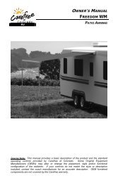
<strong>Carefree</strong> <strong>of</strong> <strong>Colorado</strong> Installation Manual APEXSTANDARD SYSTEM ADJUSTMENTSADJUSTING THE PITCHThe awning is factory set with minimum pitch. The amount <strong>of</strong> adjustment for increasing pitch may be limited bythe mounting height above a door opening. The diagram chart below provides the minimum distance requiredabove an opening with a swing-out door or window when the awning is set at MINIMUM and MAXIMUM pitch:PitchAWidth <strong>of</strong> Open DoorDoor Width 0” 12” 18” 24” 30” 36”A @ MINIMUM PITCH 1” 1.25” 1.5” 1.75” 2” 2.5”A @ MAXIMUM PITCH 1” 3.5” 5.25” 7” 8.75” 10.5”NOTE:1. Minimum Height (A) is measured from the door opening to the bottom <strong>of</strong> the mounting plate. Thevalue given is a minimum requirement.Figure 8. Mounting Height VS Pitch.CAUTIONDURING <strong>INSTALLATION</strong> OR WHEN THE PITCH OF THE AWNING IS ADJUSTED, IT IS IMPORTANT THAT THE LEAD RAILIS PARALLEL TO THE AWNING HOUSING.RTA012(Refer to Detail A, Figure 8)1. Extend the awning fully.2. On one end, loosen the 6mm hex screw located on the spring arm knuckle.3. SLIGHTLY loosen the 3/4” nut on the side <strong>of</strong> the knuckle.4. Turn the 3/4” adjustment nut located on the bottom <strong>of</strong> the knuckle.CLOCKWISE raises the pitch, COUNTERCLOCKWISE lowers the pitch.NOTE: When raising the pitch, it is helpful to have asecond person lift up on the lead rail.5. Repeat steps 2 through 4 for the other end. Note the cautioninformation above.6. When the pitch adjustments are completed, tighten the 6mmscrew and the 3/4” nut on the side <strong>of</strong> the knuckle.DETAIL AWhen the pitch is adjusted, it is necessary to adjust the angle <strong>of</strong>the lead rail for the awning to close correctly. (refer to Detail B,Figure 8)7. SLIGHTLY loosen the 3/4” nut on the side <strong>of</strong> each arm knuckleon the lead rail.8. Turn the INSIDE 6mm hex screws <strong>of</strong> each knuckle to increaseor decrease the angle <strong>of</strong> the lead rail. The bottom <strong>of</strong> the leadrail should be parallel with the ground.3/4” NutDETAIL B9. When the lead rail adjustments are completed, tighten the 3/4”nut on the side <strong>of</strong> the knuckles.Lead Rail (ref)3/4” NutOn Side <strong>of</strong> Knuckle6mm Hex Screw3/4” Adjustment Nut6mm Hex ScrewFigure 9. Pitch Adjustment.RTA013522522-002r4 17
APEX Installation Manual <strong>Carefree</strong> <strong>of</strong> <strong>Colorado</strong>SETTING THE MOTOR LIMITSThe motor limit switches are preset at the factory for best operation <strong>of</strong> the awning. The “OUT” limit switch isused to stop the motor when the awning is fully extended. The “IN” limit switch is used to stop the motorwhen the awning is fully retracted. The “IN” limit is NOT USED when the Direct Response system is installed.The limit switches are located inside the case, near the end cap. To access the switches, remove the smallrubber plugs next to the end cap or end plate.NOTE: On early units, it is necessary to open the top cover to access the limit switches. Refer tothe details below.Adjusting the OUT Limit SwitchNOTE: During normal operation, the awningwill extend out completely then rollback to provide tension to the fabric.1. Extend the awning out completely.2. Confirm that the arms are fully extended. Themotor should stop and the fabric should betight. If the motor continues to run, the fabricwill sag; or, if the motor quits before the armsare extended, it will be necessary to adjust the“OUT” limit switch.3. Using a 4mm Allen wrench turn the “OUT” limitswitch. CLOCKWISE increases time the motorruns during extension, COUNTERCLOCKWISEreduces the time the motor runs.NOTE: It is best to make theadjustments in increments <strong>of</strong> asingle turn. 3 full turns <strong>of</strong> thescrew equals approximately 2”<strong>of</strong> fabric extension.“IN”Limit Switch“OUT”Limit SwitchTop CoverIncreaseDecreaseLH MotorLead RailIncreaseDecreaseRemove ScrewEnd CapOn Units Built Before June 2005Remove End Capsto Access Cover Attach ScrewRH MotorTop CoverFigure 10. Motor Limit Switches.4. Extend and retract the awning several times to confirm that the adjustment is correct.5. Repeat steps 3 and 4 as required until the awning extends correctly.“OUT”Limit Switch“IN”Limit SwitchLimit Switches are4mm Allen HeadRemove ScrewAdjusting the IN Limit SwitchNOTE: The “IN” limit switch is not adjusted when the Direct Response system is installed. The systemelectronics monitors the motor and shuts the motor <strong>of</strong>f when the awning is fully retracted.If the IN limit switch is accidentally adjusted, the motor may shut <strong>of</strong>f before the awning is fully closed. If this occurs,turn the IN adjustment screw clockwise. It is not necessary that the screw matches the closed position. Theelectronics control the closed position.RTA014b<strong>MANUAL</strong> OVERRIDE1. If 110V power is not available to the coach, the Apex awning can still besafely retracted using the manual override. The bypass is locatedinside the case, near the end cap. Remove the large rubber pluglocated toward the rear <strong>of</strong> the case on the motor side <strong>of</strong> the awning.NOTE: On early units, it is necessary to open the top cover toaccess the override. Refer to the details on page 18.2. Chuck the 7mm hex key into a 3/8” battery powered drill.3. Insert the hex key into the manual override on the awning.4. Operate the drill in the direction shown in the diagram to close theawning. Reverse the drill to open the awning.5. When done, reinsert the rubber plug.OpenCloseLH Motor7mm HexManualOverrideLead RailOpenCloseRH MotorRTA015aFigure 11. Manual Override Access.18 052522-002r4