INSTALLATION MANUAL - Carefree of Colorado
INSTALLATION MANUAL - Carefree of Colorado
INSTALLATION MANUAL - Carefree of Colorado

You also want an ePaper? Increase the reach of your titles
YUMPU automatically turns print PDFs into web optimized ePapers that Google loves.
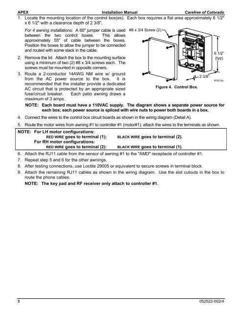
APEX Installation Manual <strong>Carefree</strong> <strong>of</strong> <strong>Colorado</strong>1. Locate the mounting location <strong>of</strong> the control box(es). Each box requires a flat area approximately 6 1/2"x 6 1/2" with a clearance depth <strong>of</strong> 2 3/8".For 4 awning installations: A 60" jumper cable is used #8 x 3/4 Screw (2)between the two control boxes. This allowsapproximately 55" <strong>of</strong> cable between the boxes.Position the boxes to allow the jumper to be connectedand routed with some slack in the cable.2. Remove the lid. Attach the box to the mounting surfaceusing a minimum <strong>of</strong> two (2) #8 x 3/4 screws each. Thescrews must be mounted in opposite corners.3. Route a 2-conductor 14AWG NM wire w/ groundfrom the AC power source to the box. It isrecommended that the installer provide a dedicatedAC circuit that is protected by an appropriate sizedFigure 4. Control Box.fuse/circuit breaker. Each patio awning draws amaximum <strong>of</strong> 3 amps.NOTE: Each board must have a 110VAC supply. The diagram shows a separate power source foreach box; each power source is spliced with wire nuts to power both boards in a box.4. Connect the wires to the control box circuit boards as shown in the wiring diagram (Detail A).5. Route the motor wires from awning #1 to controller #1 (motor#1); attach the wires to the terminals as shown.NOTE: For LH motor configurations:RED WIRE goes to terminal (1); BLACK WIRE goes to terminal (2).For RH motor configurations:RED WIRE goes to terminal (2): BLACK WIRE goes to terminal (1).6. Attach the RJ11 cable from the sensor <strong>of</strong> awning #1 to the "AMD" receptacle <strong>of</strong> controller #1.7. Repeat step 5 and 6 for the other awnings.8. After testing connections, use Loctite 29005 or equivalent to secure screws in terminal block.9. Attach the remaining RJ11 cables as shown in the wiring diagram. Use the slot cutouts in the box toroute the phone cables.NOTE: The key pad and RF receiver only attach to controller #1.2 3/8”6 1/2”(typ)RTA019c8 052522-002r4