INSTALLATION MANUAL - Carefree of Colorado
INSTALLATION MANUAL - Carefree of Colorado
INSTALLATION MANUAL - Carefree of Colorado

You also want an ePaper? Increase the reach of your titles
YUMPU automatically turns print PDFs into web optimized ePapers that Google loves.
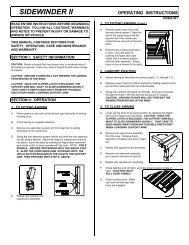
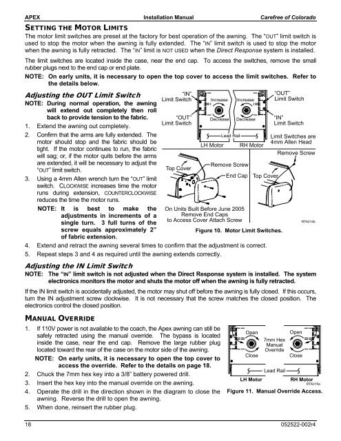
APEX Installation Manual <strong>Carefree</strong> <strong>of</strong> <strong>Colorado</strong>SETTING THE MOTOR LIMITSThe motor limit switches are preset at the factory for best operation <strong>of</strong> the awning. The “OUT” limit switch isused to stop the motor when the awning is fully extended. The “IN” limit switch is used to stop the motorwhen the awning is fully retracted. The “IN” limit is NOT USED when the Direct Response system is installed.The limit switches are located inside the case, near the end cap. To access the switches, remove the smallrubber plugs next to the end cap or end plate.NOTE: On early units, it is necessary to open the top cover to access the limit switches. Refer tothe details below.Adjusting the OUT Limit SwitchNOTE: During normal operation, the awningwill extend out completely then rollback to provide tension to the fabric.1. Extend the awning out completely.2. Confirm that the arms are fully extended. Themotor should stop and the fabric should betight. If the motor continues to run, the fabricwill sag; or, if the motor quits before the armsare extended, it will be necessary to adjust the“OUT” limit switch.3. Using a 4mm Allen wrench turn the “OUT” limitswitch. CLOCKWISE increases time the motorruns during extension, COUNTERCLOCKWISEreduces the time the motor runs.NOTE: It is best to make theadjustments in increments <strong>of</strong> asingle turn. 3 full turns <strong>of</strong> thescrew equals approximately 2”<strong>of</strong> fabric extension.“IN”Limit Switch“OUT”Limit SwitchTop CoverIncreaseDecreaseLH MotorLead RailIncreaseDecreaseRemove ScrewEnd CapOn Units Built Before June 2005Remove End Capsto Access Cover Attach ScrewRH MotorTop CoverFigure 10. Motor Limit Switches.4. Extend and retract the awning several times to confirm that the adjustment is correct.5. Repeat steps 3 and 4 as required until the awning extends correctly.“OUT”Limit Switch“IN”Limit SwitchLimit Switches are4mm Allen HeadRemove ScrewAdjusting the IN Limit SwitchNOTE: The “IN” limit switch is not adjusted when the Direct Response system is installed. The systemelectronics monitors the motor and shuts the motor <strong>of</strong>f when the awning is fully retracted.If the IN limit switch is accidentally adjusted, the motor may shut <strong>of</strong>f before the awning is fully closed. If this occurs,turn the IN adjustment screw clockwise. It is not necessary that the screw matches the closed position. Theelectronics control the closed position.RTA014b<strong>MANUAL</strong> OVERRIDE1. If 110V power is not available to the coach, the Apex awning can still besafely retracted using the manual override. The bypass is locatedinside the case, near the end cap. Remove the large rubber pluglocated toward the rear <strong>of</strong> the case on the motor side <strong>of</strong> the awning.NOTE: On early units, it is necessary to open the top cover toaccess the override. Refer to the details on page 18.2. Chuck the 7mm hex key into a 3/8” battery powered drill.3. Insert the hex key into the manual override on the awning.4. Operate the drill in the direction shown in the diagram to close theawning. Reverse the drill to open the awning.5. When done, reinsert the rubber plug.OpenCloseLH Motor7mm HexManualOverrideLead RailOpenCloseRH MotorRTA015aFigure 11. Manual Override Access.18 052522-002r4