INSTALLATION MANUAL - Carefree of Colorado
INSTALLATION MANUAL - Carefree of Colorado
INSTALLATION MANUAL - Carefree of Colorado
You also want an ePaper? Increase the reach of your titles
YUMPU automatically turns print PDFs into web optimized ePapers that Google loves.
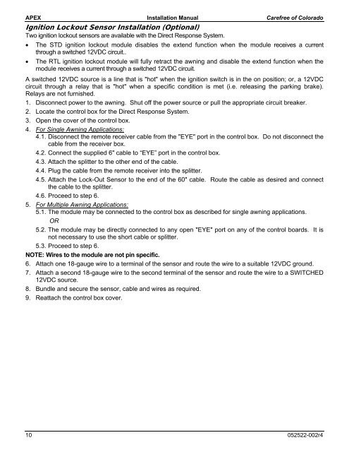
APEX Installation Manual <strong>Carefree</strong> <strong>of</strong> <strong>Colorado</strong>Ignition Lockout Sensor Installation (Optional)Two ignition lockout sensors are available with the Direct Response System. The STD ignition lockout module disables the extend function when the module receives a currentthrough a switched 12VDC circuit.. The RTL ignition lockout module will fully retract the awning and disable the extend function when themodule receives a current through a switched 12VDC circuit.A switched 12VDC source is a line that is "hot" when the ignition switch is in the on position; or, a 12VDCcircuit through a relay that is "hot" when a specific condition is met (i.e. releasing the parking brake).Relays are not furnished.1. Disconnect power to the awning. Shut <strong>of</strong>f the power source or pull the appropriate circuit breaker.2. Locate the control box for the Direct Response System.3. Open the cover <strong>of</strong> the control box.4. For Single Awning Applications:4.1. Disconnect the remote receiver cable from the "EYE" port in the control box. Do not disconnect thecable from the receiver box.4.2. Connect the supplied 6" cable to “EYE” port in the control box.4.3. Attach the splitter to the other end <strong>of</strong> the cable.4.4. Plug the cable from the remote receiver into the splitter.4.5. Attach the Lock-Out Sensor to the end <strong>of</strong> the 60" cable. Route the cable as desired and connectthe cable to the splitter.4.6. Proceed to step 6.5. For Multiple Awning Applications:5.1. The module may be connected to the control box as described for single awning applications.OR5.2. The module may be directly connected to any open "EYE" port on any <strong>of</strong> the control boards. It isnot necessary to use the short cable or splitter.5.3. Proceed to step 6.NOTE: Wires to the module are not pin specific.6. Attach one 18-gauge wire to a terminal <strong>of</strong> the sensor and route the wire to a suitable 12VDC ground.7. Attach a second 18-gauge wire to the second terminal <strong>of</strong> the sensor and route the wire to a SWITCHED12VDC source.8. Bundle and secure the sensor, cable and wires as required.9. Reattach the control box cover.10 052522-002r4


