Vertical multi-stage centrifugal pumps - DP pumps
Vertical multi-stage centrifugal pumps - DP pumps
Vertical multi-stage centrifugal pumps - DP pumps

Create successful ePaper yourself
Turn your PDF publications into a flip-book with our unique Google optimized e-Paper software.
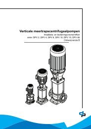
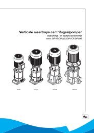
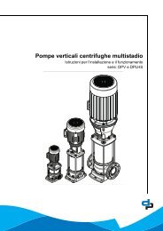
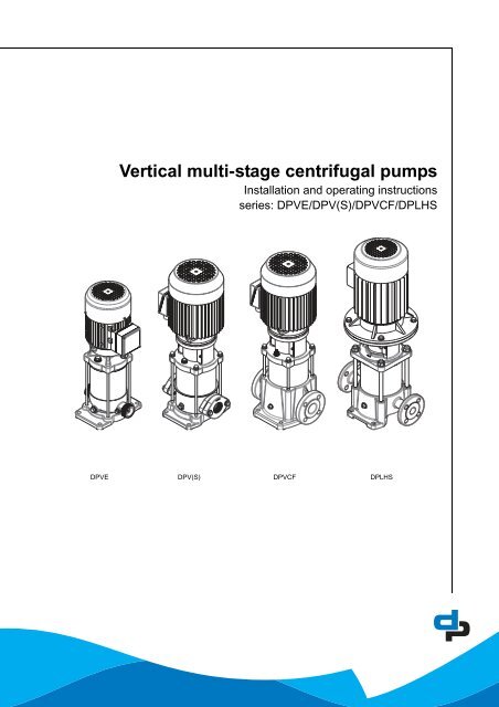
<strong>Vertical</strong> <strong>multi</strong>-<strong>stage</strong> <strong>centrifugal</strong> <strong>pumps</strong><br />
Installation and operating instructions<br />
series: <strong>DP</strong>VE/<strong>DP</strong>V(S)/<strong>DP</strong>VCF/<strong>DP</strong>LHS<br />
<strong>DP</strong>VE <strong>DP</strong>V(S) <strong>DP</strong>VCF <strong>DP</strong>LHS
2<br />
Table of Contents<br />
1 Manual Introduction<br />
1.1 Preface .................................................................................................................................................. 4<br />
1.2 Icons and symbols ................................................................................................................................ 4<br />
2 Identification, service and technical support<br />
2.1 Obtaining data and information ............................................................................................................. 5<br />
2.2 Nominal current ..................................................................................................................................... 6<br />
2.3 Supplementary documentation ............................................................................................................. 6<br />
3 Warranty<br />
3.1 Terms of warranty ................................................................................................................................. 7<br />
4 Safety and environment<br />
4.1 General ................................................................................................................................................. 8<br />
4.2 Users ..................................................................................................................................................... 8<br />
4.3 Safety provisions ................................................................................................................................... 8<br />
4.4 Safety precautions ................................................................................................................................ 8<br />
4.5 Environmental aspects .......................................................................................................................... 9<br />
5 Pump Introduction<br />
5.1 General ............................................................................................................................................... 10<br />
5.2 Intended use ....................................................................................................................................... 10<br />
5.3 Working range ..................................................................................................................................... 10<br />
5.4 Explosion safety ...................................................................................................................................11<br />
5.5 Operation ............................................................................................................................................ 14<br />
6 Transport<br />
6.1 Transport ............................................................................................................................................. 15<br />
6.2 Weight ................................................................................................................................................. 16<br />
6.3 Storage ................................................................................................................................................ 16<br />
7 Installation instructions<br />
7.1 Setting up the pump ............................................................................................................................ 17<br />
7.2 Mounting a motor on the pump ........................................................................................................... 18<br />
7.3 Electrical install ................................................................................................................................... 20<br />
7.4 Commissioning ................................................................................................................................... 21<br />
8 Operation<br />
8.1 Operation ............................................................................................................................................ 23<br />
9 Maintenance<br />
9.1 Introduction ......................................................................................................................................... 24<br />
9.2 Lubrication .......................................................................................................................................... 24<br />
9.3 Maintaining the pump for an extended period of non-operation ......................................................... 24<br />
9.4 Replace <strong>DP</strong>VE non-return valve ......................................................................................................... 24<br />
10 Failures<br />
10.1 Failure table ........................................................................................................................................ 25
11 Annexes<br />
11.1 Spare part kits ..................................................................................................................................... 28<br />
11.2 Technical specifications ...................................................................................................................... 43<br />
11.3 Torques of coupling shell - pos 914.01 ............................................................................................... 45<br />
11.4 EC declaration of conformity ............................................................................................................... 46<br />
3
4<br />
1 Manual Introduction<br />
1.1 Preface<br />
This manual contains important information for<br />
reliable proper and efficient operation. Compliance<br />
with the operating instructions is of vital importance to<br />
ensure reliability and a long service life of the product<br />
and to avoid any risks.<br />
The first chapters contain information about this<br />
manual and safety in general. The following chapters<br />
provide information about normal use, installation,<br />
maintenance and repairs of the product. The annexes<br />
contain the technical data, the parts drawings and the<br />
declaration(s) of conformity.<br />
• Make yourself familiar with the content.<br />
• Accurately follow the directions and instructions.<br />
• Never change the sequence of the operations to<br />
be carried out.<br />
• Keep this manual or a copy of it together with the<br />
logbook in a fixed place near the product which<br />
can be accessed by all personnel.<br />
1.2 Icons and symbols<br />
In this manual and in all accompanying<br />
documentation the following icons and symbols are<br />
used.<br />
WARNING<br />
Danger of electric Voltage. Safety sign<br />
according to IEC 417 - 5036<br />
WARNING<br />
Operations or procedures, if carried out<br />
without caution, may cause personal<br />
injury or damage to the product.<br />
General hazard sign according to ISO<br />
7000-0434<br />
ATTENTION<br />
Is used to introduce safety instructions<br />
whose non-observance may lead to<br />
damage to the product and its<br />
functions.<br />
ENVIRONMENTAL INSTRUCTION<br />
Remarks with respect to the<br />
environment.
2 Identification, service and technical<br />
support<br />
2.1 Obtaining data and<br />
information<br />
The name plate indicates the type series / size, main<br />
operating data and identification number. Please<br />
quote this information (first two lines*) in all queries,<br />
repeat orders and particularly when ordering spare<br />
parts. If you need any additional information or<br />
instructions exceeding the scope of this manual or in<br />
case of damage please contact <strong>DP</strong>-Pumps's nearest<br />
customer service centre.<br />
ID2446/13062005<br />
duijvelaar pompen<br />
dp <strong>pumps</strong> Holland<br />
Q: H:<br />
I nom:<br />
Pump with motor<br />
Ser.Nr:<br />
P: n:<br />
Indication Meaning<br />
<strong>DP</strong>V 4-40 Pump type *<br />
S: / ser.nr. Serial number *<br />
19/2004/234567 19 Production week *<br />
2446/13062005<br />
ID 2517/13062005<br />
Pump without motor<br />
ID 2470/07052004<br />
H nom<br />
duijvelaar pompen<br />
dp <strong>pumps</strong> Holland<br />
Q: H:<br />
2004 Production year *<br />
234567 Product identification (as built file) *<br />
Ca / Sic / EPDM Ca Rotating part mechanical seal (Carbon) *<br />
Sic Stationary part mechanical seal (Silicon carbide) *<br />
EPDM Static sealing, O-rings (EPDM) *<br />
PN 10 Pressure class (flange) connection *<br />
Q m3 /h - l/sec. - USGPM Nominal capacity (see Q/H curve above)<br />
H mWc - PSI Nominal head (see Q/H curve above)<br />
1 Inom A Nominal current (see 2.2)<br />
n 1 /min Nominal rotation speed<br />
P kW - HP Installed motor power on the pump<br />
Preq kW - HP Required motor power for the pump<br />
P.req:<br />
Ser.Nr:<br />
P: n:<br />
1. For <strong>pumps</strong> delivered with special motors no values are given (please use values as indicated on the motor plate).<br />
Q nom<br />
2517/13062005<br />
2470/07052004<br />
5
6<br />
The following address data are available for service<br />
and technical support:<br />
<strong>DP</strong>-Pumps<br />
service department<br />
Kalkovenweg 13<br />
2401 LJ Alphen a/d Rijn<br />
The Netherlands<br />
2.2 Nominal current<br />
Tel: +31 172 488388<br />
Fax: +31 172 468930<br />
Internet: www.dp-<strong>pumps</strong>.com<br />
E-mail: dp@dp-<strong>pumps</strong>.com<br />
The maximum allowable current of the motor is<br />
mentioned as I.max. on the motor plate. This<br />
maximum allowable current shows the maximum<br />
working range of the motor and can be used to<br />
protect the motor.<br />
WARNING<br />
Be careful in using it this way, because,<br />
not only the motor, but also the pump<br />
has to be protected in its application.<br />
On the pump plate (sleeve sticker) this "pump current<br />
at 400 Volts" will be mentioned as I nom. and can be<br />
used to pre-set the motor protection switch to protect<br />
the pump/motor combination.<br />
ID 2446/13062005<br />
duijvelaar pompen<br />
dp <strong>pumps</strong> Holland<br />
Q: H:<br />
I nom:<br />
Ser.Nr:<br />
This current value can also be used to determine the<br />
proper electrical equipment such as variable<br />
frequency drive, main switch, wiring diameter etc.<br />
2.3 Supplementary<br />
documentation<br />
P: n:<br />
Apart from this manual, the documentation given<br />
below is also available:<br />
Document Date/version Code<br />
General terms of delivery 10-1998 119 / 1998<br />
Engineering Reference Book 11-2008 BE00000329<br />
Technical Data 50Hz 10-2010 97004434<br />
Technical Data 60Hz 10-2010 97004435<br />
Motec operating instructions<br />
See also www.dp-<strong>pumps</strong>.com<br />
09-2001 BA-8200-motec-frequency-inverters-V3-0.EM<br />
2446/13062005
3 Warranty<br />
3.1 Terms of warranty<br />
The warranty period is settled by terms of your<br />
contract or at least by the general terms and<br />
conditions of sales.<br />
ATTENTION<br />
Modifications or alterations of the<br />
product supplied are only permitted<br />
after consultation with the<br />
manufacturer. Original spare parts and<br />
accessories authorized by the<br />
manufacturer ensure safety. The use of<br />
other parts can invalidate any liability of<br />
the manufacturer for consequential<br />
damage.<br />
ATTENTION<br />
The warranty relating to the operating<br />
reliability and safety of the product<br />
supplied is only valid if the product is<br />
used in accordance with its designated<br />
use as described in the following<br />
sections of this manual. The limits<br />
stated in the data sheet must not be<br />
exceeded under any circumstances.<br />
The warranty becomes invalid if one or more of the<br />
points below occur.<br />
• The buyer makes modifications himself.<br />
• The buyer carries out repairs himself or has<br />
these carried out by a third party.<br />
• The product has been handled or maintained<br />
improperly.<br />
• The product has non original <strong>DP</strong>-Pumps spare<br />
parts fitted.<br />
<strong>DP</strong>-Pumps remedies defects under warranty if the<br />
points below are observed.<br />
• Defects are caused by flaws in the design, the<br />
materials or the production.<br />
• The defect has been reported within the<br />
warranty period.<br />
Other terms of warranty have been included in the<br />
general terms of delivery, which are available upon<br />
request.<br />
7
8<br />
4 Safety and environment<br />
4.1 General<br />
This <strong>DP</strong>-Pumps product has been developed using<br />
state-of-the-art technology; it is manufactured with<br />
utmost care and subject to continuous quality control.<br />
<strong>DP</strong>-Pumps does not accept any liability for damage<br />
and injury caused by not observing the directions and<br />
instructions in this manual. This also applies in cases<br />
of carelessness during the installation procedure, use<br />
and maintenance of the product.<br />
Non-compliance with safety instructions can<br />
jeopardize the safety of personnel, the environment<br />
and the product itself. Non-compliance with these<br />
safety instructions will also lead to forfeiture of any<br />
and all rights to claims for damages.<br />
For example, in particular non-compliance can result<br />
in:<br />
• failure of important pump/system functions,<br />
• failure of prescribed maintenance and servicing<br />
practices,<br />
• injury to persons by electrical, mechanical and<br />
chemical effects,<br />
• hazard of the environment due to leakage of<br />
hazardous substances,<br />
• explosions.<br />
Depending on specific activities, extra safety<br />
measures may be required. Contact <strong>DP</strong>-Pumps if a<br />
potential danger arises during use.<br />
4.2 Users<br />
ATTENTION<br />
The owner of the product is responsible<br />
for compliance with the local safety<br />
regulations and internal company<br />
guidelines.<br />
ATTENTION<br />
Not only must the general safety<br />
instructions laid down in this chapter<br />
on "Safety" be complied with, but also<br />
the safety instructions outlined under<br />
specific headings.<br />
All personnel involved in the operation, maintenance,<br />
inspection and installation of the product must be fully<br />
qualified to carry out the work involved.<br />
Personal responsibilities, competence and<br />
supervision must be clearly defined by the operator. If<br />
the personnel in question is not already in possession<br />
of the required know-how, appropriate training and<br />
instruction must be provided. If required, the operator<br />
may commission the manufacturer / supplier to take<br />
care of such training. In addition, the operator is<br />
responsible for ensuring that the contents of the<br />
operating instructions are fully understood by the<br />
responsible personnel.<br />
4.3 Safety provisions<br />
The product has been designed with the greatest<br />
possible care. Original parts and accessories meet<br />
the safety regulations. Modifications in the<br />
construction or the use of non-original parts may lead<br />
to a safety risk.<br />
ATTENTION<br />
Make sure that the product operates<br />
within its working range. Only then the<br />
product performance is guaranteed.<br />
4.3.1 Labels on the product<br />
The icons, warnings and instructions applied to the<br />
product are part of the safety provisions. The labels<br />
may not be removed or covered. Labels must remain<br />
legible during the entire life of the product. Replace<br />
damaged labels immediately.<br />
4.4 Safety precautions<br />
4.4.1 During normal use<br />
• Contact the local electricity company for<br />
questions about the power supply.<br />
• Cover the parts that can become hot, so direct<br />
contact is impossible.<br />
• When applicable, always place undeformed<br />
coupling protection plates to protect the<br />
coupling, before putting the pump into use. Make<br />
sure that the coupling protection plates are<br />
never in contact with the running coupling.<br />
• Always close the terminal box on the pump.
4.4.2 During installation, maintenance and<br />
repair<br />
Only authorised personnel may install, maintain and<br />
inspect the product and repair electrical components.<br />
Observe the local safety regulations.<br />
WARNING<br />
Always disconnect the energy supply to<br />
the product first, before installation,<br />
maintenance and repairs. Secure this<br />
disconnection.<br />
WARNING<br />
Surfaces of a pump can be hot, after<br />
continuous operation.<br />
WARNING<br />
Make sure that no one can be near<br />
rotating components when starting a<br />
pump.<br />
WARNING<br />
Handle a pump with dangerous liquids<br />
with the utmost care. Avoid danger for<br />
persons or the environment when<br />
repairing leakages, draining liquids and<br />
venting. It is strongly recommended to<br />
place a relief barge under the pump.<br />
WARNING<br />
Immediately following completion of<br />
the work, all safety-relevant and<br />
protective devices must be re-installed<br />
and / or re-activated.<br />
WARNING<br />
Please observe all instructions set out<br />
in the chapter "Commissioning/Startup"<br />
before returning the product to<br />
service.<br />
4.5 Environmental aspects<br />
4.5.1 General<br />
The products of <strong>DP</strong>-Pumps are designed to function<br />
in an environmentally friendly way during their entire<br />
life. Therefore, when applicable, always use<br />
biodegradable lubricants for maintenance.<br />
ENVIRONMENTAL INSTRUCTION<br />
Always act according to the laws, bylaws<br />
regulations and instructions with<br />
respect to health, safety and the<br />
environment.<br />
4.5.2 Dismantling<br />
Dismantle the product and dispose of it in an<br />
environmentally friendly way. The owner is<br />
responsible for this.<br />
ENVIRONMENTAL INSTRUCTION<br />
Ask at the local government about the<br />
re-use or the environmentally friendly<br />
processing of discarded materials.<br />
9
10<br />
5 Pump Introduction<br />
5.1 General<br />
ID 2543/07072006<br />
<strong>Vertical</strong> <strong>pumps</strong>:<br />
<strong>DP</strong>VE <strong>DP</strong>V(S) <strong>DP</strong>VCF <strong>DP</strong>LHS<br />
The vertical, <strong>multi</strong>-<strong>stage</strong> <strong>centrifugal</strong> <strong>pumps</strong> <strong>DP</strong>VE,<br />
<strong>DP</strong>V(S), <strong>DP</strong>VCF and <strong>DP</strong>LHS are produced by <strong>DP</strong>-<br />
Pumps.<br />
5.2 Intended use<br />
The <strong>pumps</strong> <strong>DP</strong>VE, <strong>DP</strong>V(S), <strong>DP</strong>LHS and <strong>DP</strong>VCF are<br />
suitable to transport and increase the pressure of cold<br />
and hot water without wear to parts within the<br />
indicated working range. The transport of liquids with<br />
a different viscosity or density than water is possible<br />
as well. For this a motor with an adjusted power is<br />
used. Ask <strong>DP</strong>-Pumps or your distributor for advice.<br />
Any other or further use of the pump is not in<br />
conformity with its intended use. <strong>DP</strong>-Pumps does not<br />
accept any liability for any damage or injury that<br />
results from this. The pump is produced in<br />
accordance with the current standards and<br />
guidelines. Use the pump only in a perfect technical<br />
state, in conformance with the intended use<br />
described below.<br />
The Intended use as laid down in EN 12100-1 is the<br />
use for which the technical product is intended<br />
according to the specifications of the manufacturer.<br />
The use of the product has been described in the<br />
sales brochure and in the user manual. Always<br />
observe the instructions given in the user manual.<br />
When in doubt the product must be used as becomes<br />
evident from its construction, version and function.<br />
5.3 Working range<br />
The working range of the <strong>pumps</strong> in this series can be<br />
summarised as follows:<br />
20040265-B
Table 1: Specification of the working range<br />
Pump type<br />
Ambient<br />
temperature<br />
[°C]<br />
Liquid temperature<br />
[°C]<br />
Maximum<br />
working<br />
pressure<br />
[bar]<br />
Allowable<br />
size of<br />
solids<br />
pumped<br />
Minimum<br />
supply<br />
pressure<br />
Viscosity<br />
liquid [cSt]<br />
Density liquid<br />
[kg/m 3 ]<br />
<strong>DP</strong>VE<br />
-15<br />
to 60<br />
10 4<br />
<strong>DP</strong>V<br />
<strong>DP</strong>VF/V<br />
-15 to 100 1<br />
<strong>DP</strong>VS<br />
+4 to 40<br />
<strong>DP</strong>VSF/V<br />
-15 to 120 2<br />
<strong>DP</strong>VCF<br />
-15<br />
to<br />
120<br />
<strong>DP</strong>LHS<br />
-15<br />
to<br />
80 3<br />
16 4 25 4 16 4 25 4 25 4 40 4<br />
5µ to 1mm<br />
Not cavitation 5 .<br />
1<br />
A higher viscosity may require more motor<br />
power. 5<br />
1000<br />
A higher density may require more motor<br />
power. 5<br />
Cooling The space above the cooling fan of the motor<br />
must at least be equal to 1/4 of the diameter<br />
of the inlet of the cooling fan of the motor in<br />
order to have a sufficient supply of air.<br />
Number of<br />
Related to the motor<br />
starts<br />
6<br />
Minimum<br />
frequency<br />
[Hz]<br />
Maximum<br />
frequency<br />
[Hz]<br />
1. Using the factory option “o-ring sealing EPDM E425”<br />
the max. temp. limit is 120°C.<br />
2. When pumping water, the max. allowable liquid temp is<br />
80°C.<br />
3. Higher temperatures are possible at lower pressure.<br />
For specific limits consult your supplier.<br />
4. The total of the supply pressure and no-load delivery<br />
pressure with closed outlet shut-off valve may not<br />
exceed the maximum working pressure.<br />
5. Contact your supplier for more detailed advice.<br />
6. For standard motors see the technical specifications.<br />
When the pump is fitted with another motor brand,<br />
please consult the motor supplier.<br />
10<br />
60 7<br />
7. Pumps that are intended for 50 Hz operation, may not<br />
be connected to 60 Hz.<br />
Q [%]<br />
30<br />
25<br />
20<br />
15<br />
10<br />
5<br />
0<br />
40 50 60 70 80 90 100 110 120<br />
Figure 1: Minimum volume flows (Q) in % of Q<br />
optimum temperatures (t).<br />
Table 2: Minimum volume flows (Q min )<br />
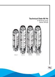
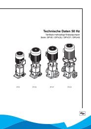
<strong>DP</strong> 50 Hz<br />
Qmin in m<br />
60 Hz<br />
3 /h<br />
6 0.8 0.8<br />
10 1.2 1.4<br />
14 1.0 1.1<br />
18 2.4 2.4<br />
24 2.2 2.6<br />
32 4.0 4.0<br />
45 4.6 5.1<br />
65 6.1 6.1<br />
Table 3: Specific applications<br />
type application area<br />
<strong>DP</strong>V (Drinking) water supply systems, irrigation<br />
systems, water treatment systems, carwash<br />
systems, sprinkler systems.<br />
<strong>DP</strong>VS Water-supply systems for drinking water,<br />
softened and demineralised water, systems<br />
for brackish water, sea water and swimming-pool<br />
water, however limited with<br />
respect to temperature, pressure and chlorine<br />
percentage.<br />
<strong>DP</strong>VCF Systems for boiler supply and discharge of<br />
condensed water<br />
<strong>DP</strong>LHS Reverse osmosis installations and high<br />
pressure cleaning systems.<br />
<strong>DP</strong>VE (Drinking) water supply systems.<br />
5.4 Explosion safety<br />
ATTENTION<br />
This sub chapter contains fundamental<br />
information which has to be taken in<br />
consideration when installing the pump<br />
with ATEX permission in a hazardous<br />
environment.<br />
5.4.1 General<br />
Stickers or indicators on the pump sleeve and the<br />
motor indicate whether the pump is suitable for use in<br />
an environment with risk of explosion.<br />
t [°C]<br />
11
12<br />
It is allowed to install the pump in a zone which is<br />
classified in directive 1999/92/EC.<br />
When in doubt it is compulsory to check the above<br />
directive.<br />
5.4.2 Indication<br />
ID2512<br />
Figure 2: Indication sticker explosion<br />
safety 2512<br />
Table 4: ATEX marking<br />
Indication Meaning<br />
II Product group for use above ground, with the<br />
exception of mine working where there can be<br />
danger of explosion due to mine gas and/or<br />
flammable substances.<br />
2 Category 2: Equipment in this category is<br />
intended for use in areas in which explosive<br />
atmospheres caused by mixtures of air and<br />
gases, vapours or mists or by air/dusts mixtures<br />
are likely to occur.<br />
3 Category 3: Equipment in this category is<br />
intended for use in areas in which explosive<br />
atmospheres caused by mixtures of air and<br />
gases, vapours or mists or by air/dusts mixtures<br />
are likely to occur or, if they do occur,<br />
are likely to do so only infrequently and for a<br />
short period only.<br />
G Suitable for an environment that is explosive<br />
due to gas, vapour or fumes; not suitable for<br />
an environment that is explosive due to dust.<br />
T4/T3 Temperature class:<br />
T4 for maximum surface temperature 135 °C<br />
T3 for maximum surface temperature 200 °C<br />
ATTENTION<br />
When the pump is placed in an<br />
explosion hazardous environment no<br />
pump should be opened or<br />
disassembled on site. Due to the<br />
probable creation of sparks during<br />
loosening and tightening of nuts and<br />
bolts.<br />
5.4.3 Medium temperature<br />
The applied ATEX motor determines the maximum<br />
allowable temperature of the pumped liquid. See<br />
table 5 Maximum medium temperatures<br />
Table 5: Maximum medium temperatures<br />
ATEX marking motor Allowable medium temperature<br />
Exe 60 °C<br />
EXd 100 °C<br />
Exde 60 °C<br />
5.4.4 Commissioning (check list)<br />
It is compulsory to check these points prior putting the<br />
pump in operation.<br />
• Check if the ATEX-data on the motor and the<br />
pump are in line with the specified category.<br />
• When the categories of the motor and the pump<br />
are different, the lowest category is leading.<br />
• Make sure that the pump is protected against<br />
damage from outside.<br />
• Make sure that the liquid temperature never<br />
exceeds the maximum allowed temperature (see<br />
table 5 Maximum medium temperatures. Apply a<br />
temperature monitoring and limiting system,<br />
meeting the requirements of EN 13463-6, that<br />
stops the pump at too high medium<br />
temperatures. Please note that the maximum<br />
temperature noted on the name plate of the<br />
pump refers to the technical specification of the
mechanical part of the pump and does not match<br />
with the maximum allowed medium temperature<br />
for ATEX applications.<br />
• Apply a monitoring and limiting system, meeting<br />
the requirements of EN 13463-6, to prevent dry<br />
running. It has to check the presence of the<br />
medium at the inlet of the pump and stop the<br />
pump when no medium is available.<br />
• Apply a monitoring and limiting system, meeting<br />
the requirements of EN 13463-6, to secure that<br />
the maximum current of the motor is not<br />
exceeded.<br />
• If the motor is suited with a PTC; connect the<br />
PTC to a monitoring and limiting system.<br />
• Check if the motor cable is suitable for the<br />
current drawn by the motor. See: motor type<br />
plate.<br />
• Check if the pump is fully filled with the liquid<br />
(de-aerated). Do not run the pump dry.<br />
• Check the rotational direction of the motor. The<br />
motor has to run clockwise (seen from the non<br />
driven side). This direction is indicated with an<br />
arrow on the pump top bracket.<br />
• Do not apply higher pressures in the pump than<br />
specified in the name plate as being allowed at<br />
the working temperature of the medium.<br />
• Do not operate the pump at flows lower than<br />
specified in ‘Working range’.<br />
• Do not operate the pump at flows higher then<br />
specified in the performance curve (see the<br />
technical documentation).<br />
• Do not operate the <strong>pumps</strong> with inlet pressures<br />
lower than specified in the NPSH req<br />
requirements (NPSH req + 1 m) in to the technical<br />
documentation.<br />
• Make sure that the maximum particle sizes in the<br />
medium does not exceed the values specified in<br />
chapter 5.3 Working range.<br />
• The <strong>pumps</strong> has to be de-aerated again when:<br />
• the pump is taken out of operation;<br />
• some air has gathered in the pump.<br />
• Wrong adjustment of the coupling can cause<br />
interference of pump parts. Assembling and<br />
adjusting of the coupling has to be performed by<br />
a certified mechanic from the supplier of the<br />
pump. This holds if only a pump or a thrust<br />
bearing housing is supplied but also if for<br />
another reason the pump coupling has to be<br />
assembled or adjusted.<br />
• Make sure the coupling guard is assembled.<br />
• Wrong assembly of the coupling guard could<br />
cause it to vibrate during operation of the pump<br />
or cause interference of pump parts. If the<br />
coupling guard has to be (re)assembled, this has<br />
to be done by a certified mechanic from the<br />
supplier of the pump.<br />
• Make sure that the pump and the motor shaft are<br />
running smoothly and without excessive noise<br />
(e.g. no parts are running against each other).<br />
• Wrong assembling of the mechanical seal can<br />
cause malfunction of the pump. Assembling of<br />
the cartridge or easy access seal has to be done<br />
by a certified mechanic from the supplier of the<br />
pump. This holds when the mechanical seal is<br />
replaced or for another reason a cartridge/easy<br />
access seal has to be assembled.<br />
• Make sure that only media is pumped that is<br />
compatible with the seals and elastomers that<br />
are applied in the pump (see technical<br />
documentation).<br />
• Electric installation of the pump motor has to be<br />
done by a ATEX certified mechanic.<br />
• The pump has to be equipotent bonded with the<br />
surrounding parts of the installation.<br />
• When a flammable medium is pumped, do not<br />
pump this medium at a higher temperature than<br />
the ignition temperature of the medium plus<br />
25 °C.<br />
• Take care that if a formerly intensively used<br />
pump has not been used for some time, at high<br />
pressures leakage at the shroud could find<br />
place.<br />
• Do not pump different mediums with the pump<br />
which can have chemical reactions with each<br />
other.<br />
If the pump is supplied without motor, it is compulsory<br />
to also check the following additional points prior<br />
putting the pump in operation:<br />
• Wrong adjustment of the coupling can cause<br />
interference of pump parts. Assembling and<br />
adjusting of the coupling has to be performed by<br />
a certified mechanic from the supplier of the<br />
pump.<br />
• Apply a motor that is ATEX certified for<br />
equipment group IIG (non-mining and gas).<br />
• For the ATEX specialisation of category,<br />
temperature class and possibly explosion group<br />
of the assembly of pump and motor the lowest<br />
specification is applicable. The determination of<br />
the ATEX specification of the assembly and<br />
certification is the responsibility of the owner of<br />
the pump/motor.<br />
• Apply a motor that has a special bearing which is<br />
suited to support the high axial loads of the<br />
pump shaft. If this is not the case, a thrust<br />
bearing housing has to be applied.<br />
13
14<br />
• Apply a motor with a nominal power which is<br />
suited to drive the pump at the operating<br />
frequency.<br />
• Apply a motor that has the proper frame size to<br />
connect with the motor stool.<br />
If a pump supplied with thrust bearing housing or a<br />
solely supplied thrust bearing housing is supplied, it is<br />
compulsory to also check the following additional<br />
points prior to putting the pump in operation:<br />
• Wrong adjustment of the axial play between the<br />
thrust bearing housing shaft and the motor shaft<br />
could cause too high impacts between these<br />
shafts. Assembling of the electric motor with the<br />
thrust bearing housing has to be done by a<br />
certified mechanic from the supplier of the pump.<br />
• When the thrust bearing housing has a grease<br />
nipple, the thrust bearing can be lubricated.<br />
Proper lubrication is important to prevent high<br />
temperatures in the bearing. If the thrust bearing<br />
housing has a grease nipple it is obligatory to<br />
supply on a yearly basis some grease through<br />
this nipple to the bearing.<br />
• Do not install the pump upside-down.<br />
5.5 Operation<br />
The liquid is sucked in through the pump inlet (A) on<br />
the supply side under minimum pressure. The pump<br />
increases the pressure. The liquid leaves the pump<br />
through the pump outlet (B) on the delivery side under<br />
increased pressure.<br />
ID 0304/02072003<br />
A Pump inlet<br />
B Pump outlet<br />
C Terminal box<br />
D Fill plug/air relief plug<br />
E Drain plug<br />
C<br />
A<br />
D<br />
B E<br />
0304/02072003<br />
ID 2458/07052004<br />
A<br />
B<br />
2458/07052004
6 Transport<br />
6.1 Transport<br />
1. Transport the pump in the position as indicated<br />
on the pallet or packaging.<br />
2. Make sure the pump is stable.<br />
3. If present, observe the instructions on the<br />
packaging.<br />
WARNING<br />
Lift the pump, if necessary using a hoist<br />
and suitable slings. Attach the slings to<br />
the transport lugs on the packaging,<br />
where present.<br />
WARNING<br />
The pump must be lifted according to<br />
the current hoist guidelines. Only<br />
qualified personnel are allowed to lift<br />
the pump.<br />
WARNING<br />
Do not lift the pump by using the<br />
frequency converter (if placed),<br />
electrical parts or the motor cover. Be<br />
sure that the pump is always in balance.<br />
WARNING<br />
All the <strong>pumps</strong> will turn approximately 2<br />
to 15 degrees. Do not remove the lever<br />
or protection from the pump before the<br />
pump is placed and mounted correctly.<br />
20050327<br />
20050327<br />
15
16<br />
6.2 Weight<br />
Motor Minimum<br />
weight<br />
6.3 Storage<br />
Maximum<br />
weight<br />
Minimum<br />
weight with<br />
frequency<br />
converter<br />
Fill the pump with glycol in order to protect it against<br />
the risk of frost.<br />
Table 6: Storage<br />
6.3.1 Inspection during storage<br />
1. Turn the shaft every three months and just<br />
before putting into operation.<br />
Maximum<br />
weight with<br />
frequency<br />
converter<br />
kW (kg) (kg) (kg) (kg)<br />
0.37 11 14 18 21<br />
0.55 13 23 20 30<br />
0.75 16 24 23 31<br />
1.1 19 61 26 68<br />
1.5 25 63 32 70<br />
2.2 29 72 38 81<br />
3 43 82 52 91<br />
4 49 86 59 96<br />
5.5 81 120 71.5 130.5<br />
7.5 68 138 78.5 148.5<br />
Storage<br />
tambient [°C] -10/+40<br />
Max. rel. humidity 80% at 20°C not condensing
7 Installation instructions<br />
7.1 Setting up the pump<br />
ID 0238/23062003<br />
ID 2637/15062005<br />
ATTENTION<br />
Make sure that the pump connections<br />
are stress-less installed (e.g. no heavy<br />
load on the inlet and outlet<br />
connections). It is to be advised to use<br />
pipe-compensators, see drawing above.<br />
Only on the condition that the pump is<br />
provided with a reinforced cast casing,<br />
model <strong>DP</strong>VCF, the top/down force on<br />
the flanges can be in accordance with<br />
the table below.<br />
Table 7: Allowable forces <strong>DP</strong>VCF<br />
Type DN<br />
Force [N]<br />
[mm] Fx Fy Fz Σ F<br />
<strong>DP</strong>VCF 2 25 36000 6800 10400 38100<br />
<strong>DP</strong>VCF 4 32 38000 7200 11000 40200<br />
<strong>DP</strong>VCF 10 40 45000 18000 20000 52400<br />
<strong>DP</strong>VCF 18 50 70000 25000 23000 77800<br />
<strong>DP</strong>VCF 32 65 54000 25000 44000 74000<br />
<strong>DP</strong>VCF 45 80 48000 17000 31000 59600<br />
<strong>DP</strong>VCF 65 100 60000 21000 33000 71600<br />
20070301-C<br />
0238/23062003<br />
20050373<br />
Table 8: Allowable moment <strong>DP</strong>VCF<br />
Type DN<br />
Moment [Nm]<br />
[mm] Mx My Mz Σ M<br />
<strong>DP</strong>VCF 2 25 700 800 1200 1600<br />
<strong>DP</strong>VCF 4 32 700 800 1200 1600<br />
<strong>DP</strong>VCF 10 40 1100 1000 2600 3000<br />
<strong>DP</strong>VCF 18 50 2200 1300 2600 3600<br />
<strong>DP</strong>VCF 32 65 2300 1700 2000 3500<br />
<strong>DP</strong>VCF 45 80 2700 2700 2300 4500<br />
<strong>DP</strong>VCF 65 100 3300 3600 3000 5700<br />
20070301-C<br />
ATTENTION<br />
The values mentioned in the tables<br />
above are given for the point at which a<br />
maximal tension of between 200 and<br />
205 MPa occurs. It is assumed that the<br />
3 forces or the 3 moments as given in<br />
the drawing below occur<br />
simultaneously.<br />
20070301-B<br />
ATTENTION<br />
Pumps that do not stand steady or<br />
stable of their own, should be mounted<br />
on a ridged and stable base.<br />
17
18<br />
ATTENTION<br />
Place the pump there where there is the<br />
lowest risk for noise nuisance.<br />
1. Place and install the pump on a level, stable<br />
surface in a dry and frost-proof room.<br />
2. Make sure that sufficient air can reach the<br />
cooling fan of the motor. For this purpose the<br />
free space above the cooling fan should be at<br />
least 1/4 of the diameter of the fan cover air<br />
intake.<br />
3. Install the pump with counter flanges. Pumps<br />
with non-standardised connections; counter<br />
flanges are delivered separately.<br />
4. Install a valve on the supply and on the delivery<br />
connection of the pump.<br />
5. If there is a chance that when the pump is<br />
standing still the medium can flow back, it is<br />
advised to install a non-return valve.<br />
6. Make sure that the inlet of the pump is never<br />
clogged.<br />
7.1.1 Indicators<br />
ID 0237/24062003<br />
The arrow (A) on the pump foot indicates the flow<br />
direction of the liquid. The arrow (B) on the top<br />
bracket indicates the rotating direction of the motor.<br />
7.1.2 Install bypass<br />
Install a bypass if the pump operates against a closed<br />
valve. The required capacity of the bypass is at least<br />
10% of the optimum volume flow. At high operating<br />
temperatures a higher volume flow is required. Refer<br />
to the table "Minimum volume flows" in the paragraph<br />
"Working range".<br />
B<br />
A<br />
0237/24062003<br />
7.2 Mounting a motor on the<br />
pump<br />
ATTENTION<br />
It is to be advised to use a special<br />
designed <strong>DP</strong>-Pumps motor. Before<br />
installing an other brand/standard IECnorm<br />
motor, <strong>DP</strong>-Pumps has to be<br />
consulted to judge the applicability.<br />
The motor has to conform to the following conditions:<br />
• Increased power output (to limit the standard<br />
installed motor power)<br />
• Reinforced bearing at driven end (to withstand<br />
the axial force)<br />
• Fixed bearing at driven end (to minimize the<br />
axial play)<br />
• Smooth shaft, no key lock (to improve the<br />
coupling grip and to improve the motor balance)<br />
The advised bearings per motor type are:<br />
[kW] Axial bearing [kW] Co-axial bearing<br />
0.37 6203-2RS-C3 11 7309-BEP<br />
0.55 6203-2RS-C3 15 7309-BEP<br />
0.75 6204-2RS-C3 18.5 7309-BEP<br />
1.1 6204-2RS-C3 22 7311-BEP<br />
1.5 6305-2Z-C3 30 7312-BEP<br />
2.2 6305-2Z-C3 37 7312-BEP<br />
3 6306-2Z-C3<br />
4 6306-2Z-C3<br />
5.5 6308-2Z-C3<br />
7.5 6308-2Z-C3
7.2.1 Install the motor on <strong>pumps</strong>, supplied<br />
without motor, with a standard<br />
mechanical seal.<br />
ID3312/20090403<br />
20090321/20090402<br />
1. Remove the coupling guards (681) and the<br />
coupling shells (862).<br />
2. Remove the seal protection bracket (89-11.03)<br />
and its mounting material. For <strong>pumps</strong> with a<br />
taper piece (722) (with motor of 5.5 kW or<br />
higher), the two bolts (914.02 or 901.02) has to<br />
be placed back to connect the taper piece to the<br />
motor stool. Thoroughly clean the motor stool<br />
(341), the shaft (210), the coupling shells (862)<br />
and the motor shaft.<br />
3. Loosely fasten the coupling shells (862) with the<br />
coupling pin (560) on the shaft (210). Use the<br />
hexagon socket head cap screw (914.01) and<br />
the nut (920.01) for this. (When the pump is<br />
equipped with a steel coupling, never use the<br />
same coupling twice but order a new one).<br />
4. Place the motor on the motor stool (341).<br />
5. Tighten the lower bolts of the coupling shells<br />
(862) in such way, that the coupling slightly<br />
clamps around the motor shaft.<br />
6. Lift the pump assembly to the maximum<br />
upwards position and mark the shaft. Use a tyre<br />
lever to lift the coupling.<br />
ID 2937/13062007<br />
20070376<br />
ATTENTION<br />
For motors of 11 kW or higher, block the<br />
rotor when adjustments are made to the<br />
coupling. This ensures that the rotor<br />
will not come out of its bearings.<br />
WARNING<br />
Correct seal tension max. -1 mm lower<br />
than the maximum upwards position!<br />
7. Position the pump assembly 1 mm lower than<br />
the maximum upwards position as mentioned<br />
earlier.<br />
8. Fully tighten the couplings at the given torque<br />
(see "Torques" in the annexes). Make sure that<br />
the gaps between the couplings are equally<br />
divided on both sides (see drawing).<br />
ID 2457/12032004<br />
20030733<br />
9. Attach the coupling guards (681) with the socket<br />
head cap screws (914.05) to the motor stool<br />
(341).<br />
10. Connect the electricity supply to the motor. see<br />
§ 7.3 Electrical install.<br />
19
20<br />
7.2.2 Installing the motor on <strong>pumps</strong>, supplied<br />
without motor, with a cartridge seal<br />
ID3312/20090403<br />
20090322/20090402<br />
1. Remove the coupling guards (681) and the<br />
coupling shells (862).<br />
2. Remove the seal protection bracket (89-11.03)<br />
and its mounting material. For <strong>pumps</strong> with a<br />
taper piece (722) (with motor of 5.5 kW or<br />
higher), the two bolts (914.02 or 901.02) has to<br />
be placed back to connect the taper piece to the<br />
motor stool. Thoroughly clean the motor stool<br />
(341), the shaft (210), the coupling shells (862)<br />
and the motor shaft.<br />
3. Loosely fasten the coupling shells (862) with the<br />
coupling pin (560) on the shaft (210). Use the<br />
hexagon socket head cap screw (914.01) and<br />
the nut (920.01) for this. (When the pump is<br />
equipped with a steel coupling, never use the<br />
same coupling twice but order a new one).<br />
4. Place the motor on the motor stool (341).<br />
5. Loosen the three cartridge grub screws (904)<br />
one turn.<br />
6. Push the hydraulic pump assembly in the lowest<br />
position.<br />
7. Tighten the three cartridge grub screws (904)<br />
firmly to the shaft.<br />
8. Tighten the lower bolts of the coupling shells<br />
(862) so that the coupling slightly clamps around<br />
the motor shaft.<br />
9. Lift the pump assembly to the maximum<br />
upwards position and mark the shaft.Use a tyre<br />
lever to lift the coupling.<br />
ID 2937/13062007<br />
20070376<br />
ATTENTION<br />
For motors of 11 kW or higher, block the<br />
rotor when adjustments are made to the<br />
coupling. This ensures that the rotor<br />
will not come out of its bearings.<br />
WARNING<br />
Correct seal tension max. -1 mm lower<br />
than the maximum upwards position!<br />
10. Position the pump assembly 1 mm lower than<br />
the maximum upwards position as mentioned<br />
earlier.<br />
11. Fully tighten the couplings at the given torque<br />
(see "Torques" in the annexes). Make sure that<br />
the gaps between the couplings are equally<br />
divided on both sides (see drawing).<br />
ID 2457/12032004<br />
20030733<br />
12. Install the coupling guards (681) with the socket<br />
head cap screws (914.05) to the motor stool<br />
(341).<br />
13. Electrically connect the motor. See § 7.3<br />
Electrical install.<br />
7.3 Electrical install<br />
WARNING<br />
Only authorised personnel is allowed to<br />
make electrical connections to the<br />
motor. This is in accordance with the<br />
local regulations.
ID 2482/10082005<br />
ATTENTION<br />
After connecting the motor according<br />
to the diagram always check the<br />
rotation direction.<br />
PTC connection STM 140 EK:<br />
• All motors 3 kW and up are equipped with a PTC<br />
thermistor. Consult: 11.2 Technical<br />
specifications 43.<br />
• Connect the PTC on a thermistor relays.<br />
7.4 Commissioning<br />
WARNING<br />
The pump must not be switched on<br />
when it is not completely filled up.<br />
ATTENTION<br />
Seen from the top of the motor the<br />
pump should rotate clockwise (B) See<br />
Indicators 18. In case of a 3-phase<br />
motor the rotating direction can be<br />
changed by exchanging two of the<br />
three phase wires.<br />
Electrical connections:<br />
• Make sure that the motor specifications<br />
correspond with the power supply to which the<br />
pump motor is connected. Consult "Electrical<br />
diagrams" in the annexes for the correct<br />
connection diagram.<br />
• Connect the motor using a motor safety switch.<br />
7.4.1 In an open or closed circuit with<br />
sufficient supply pressure<br />
ID 0239/24062003<br />
0239/24062003<br />
1. Close the suction shut-off valve (A) and the<br />
outlet shut-off valve (B).<br />
2. Open the fill plug (C).<br />
3. Gradually open the suction shut-off valve until<br />
the liquid flows from the fill plug (C).<br />
4. Close the fill plug.<br />
5. Fully open the suction shut-off valve.<br />
6. Check the rotational direction of the pump.<br />
A<br />
C<br />
B<br />
2482/10082005<br />
21
22<br />
7. Fully open the outlet shut-off valve.<br />
7.4.2 In an open circuit with a liquid level<br />
lower than the pump<br />
ID 0241/24062003<br />
0241/24062003<br />
1. Partly loosen the drain plug (A). For <strong>DP</strong>VE ,<br />
<strong>DP</strong>VCF and <strong>DP</strong>LHS the drain plug must be fully<br />
removed.<br />
2. Remove the fill plug (B) from the top bracket.<br />
3. Block the entry of the drain plug on the outside of<br />
the pump foot.<br />
4. Close the outlet shut-off valve.<br />
5. Fill the pump housing to the maximum through<br />
the fill plug with the liquid that is to be pumped.<br />
6. Screw the drain plug into the pump foot.<br />
7. Insert the fill plug in the top bracket.<br />
8. Check the rotational direction of the pump.<br />
9. Open the outlet shut-off valve.<br />
7.4.3 After an extended period of nonoperation<br />
or storage<br />
During first start-up, be sure to check the mechanical<br />
seals for leakage due to seizure or dehydration of the<br />
lubricating film. If this is the case, please proceed as<br />
follows:<br />
1. Turn shaft manually or;<br />
2. Start up the pump, then open and close the<br />
outlet shut-off valve quickly during operation.<br />
3. Check if the mechanical seal is still leaking.<br />
If the shaft is still leaking:<br />
1. Disassemble the mechanical seal.<br />
2. Thoroughly clean and degrease the running<br />
surfaces.<br />
3. Assemble the mechanical seal again and retry<br />
start-up.<br />
If this doesn’t solve the shaft leakage, replacement of<br />
the mechanical seal is necessary.<br />
B<br />
A
8 Operation<br />
8.1 Operation<br />
The pump is controlled externally and therefore does<br />
not need any operation guidance.<br />
23
24<br />
9 Maintenance<br />
9.1 Introduction<br />
WARNING<br />
Observe the general safety precautions<br />
for installation, maintenance and repair.<br />
Regular maintenance is necessary for the correct<br />
operation of a pump. For maintenance of the pump,<br />
please contact your supplier.<br />
9.2 Lubrication<br />
Standard motors, with a maximum power of 7.5 kW,<br />
are provided with maintenance free sealed bearings.<br />
Motors with lubricating nipples must be lubricated<br />
after 2000 hours. If the pump works under extreme<br />
conditions, such as vibrations and high temperatures,<br />
the motors must be lubricated more often.<br />
Use a lithium based -30 °C / 160 °C bearing lubricant<br />
(about 15 grams).<br />
When the pump is delivered without a motor and fitted<br />
with an other brand or the standard motor is replaced<br />
by an other brand than <strong>DP</strong>-Pumps, please consult the<br />
maintenance instructions of the motor supplier.<br />
ATTENTION<br />
Also follow the instructions in § 7.2<br />
Mounting a motor on the pump 18.<br />
9.3 Maintaining the pump for an<br />
extended period of nonoperation<br />
Turn the shaft every three months. This protects the<br />
seals from seizure.<br />
Protect the pump against if there is a risk of frost.<br />
Proceed as follows:<br />
1. Close all pump valves.<br />
2. Drain each pump and/or the system.<br />
3. Remove all plugs from the pump.<br />
4. Open the shut-off and fill/air vent plug, if present.<br />
9.4 Replace <strong>DP</strong>VE non-return<br />
valve<br />
ID0996<br />
Figure 3: replace VE non-return valve 0996/15082003<br />
To replace the non-return valve of the pump types<br />
<strong>DP</strong>VE, proceed as follows:<br />
1 Use a pair of pliers to remove the non-return<br />
valve.<br />
2 Remove the O-ring.<br />
3 Install a new O-ring.<br />
4 Install the new non-return valve.
10 Failures<br />
10.1 Failure table<br />
WARNING<br />
Observe the general safety precautions<br />
before install, maintenance and repair.<br />
Problem Possible cause Possible solution Checkpoints<br />
Leakage along the shaft. Running surfaces of the<br />
mechanical seal worn or<br />
damaged.<br />
New pump: seal stuck due<br />
to assembly.<br />
Leakage along the shroud<br />
at the top bracket or at the<br />
pump foot.<br />
Mechanical seal mounted<br />
incorrectly.<br />
Elastomers affected by<br />
medium.<br />
Replace the mechanical<br />
seal.<br />
Open and close the outlet<br />
shut-off valve quickly during<br />
operation.<br />
Install the mechanical seal<br />
correctly. Use water and<br />
soap as a lubricant.<br />
Use the right rubber compound<br />
for the mechanical<br />
seal.<br />
Pressure too high. Use the right type of<br />
mechanical seal.<br />
Shaft worn. Replace shaft and<br />
mechanical seal.<br />
Pump has been operating<br />
without water.<br />
Replace the mechanical<br />
seal.<br />
O-ring worn Replace the O-ring.<br />
O-ring not resistant to the<br />
medium to be pumped<br />
Too much tension on the<br />
pump foot; it becomes<br />
oval.<br />
Replace O-ring by an Oring<br />
with better resistance<br />
Decrease tension on piping<br />
Mount the pump foot tensionless<br />
Support the connections.<br />
Check the pump for dirt /<br />
abrasive parts.<br />
25
26<br />
Problem Possible cause Possible solution Checkpoints<br />
Pump is vibrating or noisy. Coupling mounted incorrectly.<br />
Faulty setting of the<br />
hydraulic assembly.<br />
There is no water in the<br />
pump.<br />
Install the coupling in parallel.<br />
Adjust the assembly<br />
according to the manual.<br />
Fill and vent the pump.<br />
No supply. Make sure there is sufficient<br />
supply. Check for<br />
blockages in the supply<br />
line.<br />
Bearings of pump and/or<br />
motor worn.<br />
Available NPSH too low<br />
(cavitation).<br />
Pump does not work in its<br />
working range.<br />
Pump is standing on an<br />
uneven surface.<br />
Malfunction. Internal blockage in the<br />
pump.<br />
Pump does not start. No voltage on the terminal<br />
clamps.<br />
The motor is running, but<br />
the pump does not work.<br />
Thermal motor safety<br />
switch triggered.<br />
The coupling between<br />
pump- and motor shaft is<br />
loose.<br />
The pump shaft has broken.<br />
Have the bearings<br />
replaced by a certified<br />
company.<br />
Improve suction condition.<br />
Select another pump or<br />
adjust the system to work<br />
within its working range.<br />
Level the surface.<br />
Have the pump inspected<br />
by a certified company.<br />
Check the power supply. • Circuit<br />
• Main switch<br />
Check the motor safety<br />
relay<br />
Reset the thermal motorsafety.<br />
Contact the supplier,<br />
if this problem occurs<br />
more often.<br />
Tighten the connecting<br />
screws to the recommended<br />
torque.<br />
Contact the supplier.<br />
• Fuses<br />
• Earth leakage switch<br />
• Protective relay<br />
Check if the correct value<br />
is set. Find the correct<br />
value (Inom ) on the motor<br />
type plate.
Problem Possible cause Possible solution Checkpoints<br />
Pump supplies insufficient<br />
capacity and/or pressure.<br />
Outlet and/or inlet shut-off<br />
valve is closed.<br />
Open both shut-off valves.<br />
There is air in the pump. Vent the pump.<br />
The suction pressure is<br />
insufficient.<br />
Pump rotates in the wrong<br />
direction.<br />
The suction line has not<br />
been vented.<br />
Air bubble in the suction<br />
line.<br />
Pump sucks air because<br />
of leakage in the suction<br />
line.<br />
Too little water consumption<br />
so air bubbles clog up<br />
in the pump.<br />
The diameter of the suction<br />
line is too small.<br />
Capacity of water meter in<br />
the supply line is too<br />
small.<br />
Increase the suction pressure.<br />
Change over L1 and L2 of<br />
the three phase supply.<br />
Vent the suction line.<br />
Install the suction line with<br />
pump end higher than the<br />
other end.<br />
Repair the leakage.<br />
Make sure the consumption<br />
increases or use a<br />
smaller pump.<br />
Increase the diameter of<br />
the suction line.<br />
Increase the capacity of<br />
the water meter.<br />
Foot valve blocked. Clean the foot valve.<br />
The impeller or the diffuser<br />
is blocked.<br />
O-ring between impeller<br />
and diffuser is gone.<br />
O-ring not resistant to the<br />
medium to be pumped.<br />
Clean the inside of the<br />
pump.<br />
Replace the O-rings.<br />
Replace O-ring by an Oring<br />
with better resistance.<br />
27
28<br />
11 Annexes<br />
11.1 Spare part kits<br />
Spare part Kit Kit Nr<br />
Fan Hood Kit<br />
832<br />
Fan hood (832) + Fan Impeller (831)<br />
Coupling Kit<br />
862<br />
4/6 x Nut (920.01) + 4/6 x hexagon socket head cap screw (914.01) + 2 x coupling shell (862) +<br />
coupling pin (560)<br />
Drain / air relief plug Kit<br />
Screwed plug (903.01) + joint ring (411.01) + screwed plug (903.02) + joint ring (411.02)<br />
Stage casing compl. with bearing Kit<br />
Stage casing with bearing (108.02) + bearing sleeve (529) + impeller (230) + spacer sleeve short (525.01)<br />
Spacer sleeve Kit<br />
2 x Spacer sleeve short (525.01) + 6 x spacer sleeve long (525.03) + spacer sleeve (525.08) + spacer sleeve seal<br />
(525.05)<br />
Sealing Kit<br />
Mechanical seal (433) + 2 x O-ring (412.01) + 2 x gasket (400)<br />
Shaft end Kit<br />
Spacer sleeve end (525.04) + lock nut (920.02) + safety device, Nord-lock (930) + circlip (932)<br />
Flange Kit<br />
2 x Flange (723) + 4/8/16 x hexagon head bolt (901.03) + 0/4/8/16 x nut (920) + 4/8/16/32 x washer (554.03) +<br />
2 x gasket (400)<br />
Terminal box kit<br />
Gasket (400.02) + terminal box (833) + terminal board (835) + gasket (400.03) + terminal box cover plate (81.37)<br />
+ 4 x screw (900)<br />
Capacitor<br />
Capacitor (837)<br />
11.1.1 Parts list<br />
number (ZN) name<br />
101 Pump casing<br />
108 Stage casing<br />
160 Cover<br />
171 Diffuser<br />
210 Shaft<br />
230 Impeller<br />
341 Motor stool<br />
400 Gasket<br />
411 Joint ring<br />
412 O-ring<br />
433 Mechanical seal<br />
471 Seal cover<br />
500 Ring<br />
509 Intermediate ring<br />
525 Spacer sleeve<br />
525.08 Spacer sleeve<br />
529 Bearing sleeve<br />
554 Washer<br />
560 Pin<br />
903<br />
10-5<br />
525<br />
433<br />
81-88<br />
723<br />
833<br />
837
number (ZN) name<br />
681 Coupling guard<br />
722 Taper piece, flanged<br />
723 Flange<br />
742 Non-return valve<br />
800 Motor<br />
801 Flanged motor<br />
802 Motor for close coupling<br />
831 Fan impeller<br />
832 fan hood<br />
833 Terminal box<br />
835 Terminal board<br />
837 Condenser<br />
862 Coupling shell<br />
890 Base plate fabricated or cast<br />
900 Screw<br />
901 Hexagon head bolt<br />
903 Screwed plug<br />
904 Grub screw<br />
905 Tie bolt<br />
913 Vent plug<br />
914 Hexagon socket head cap scr.<br />
920 Nut<br />
930 Safety device<br />
932 Circlip<br />
10-6 Pump shroud<br />
81-37 Terminal box cover plate<br />
29
30<br />
11.1.2 Parts drawing motor<br />
ID 2479/090206<br />
Figure 4: Motor exploded view 3~ 20040343-D
11.1.3 Parts drawing <strong>DP</strong>VE 2/4/10/14<br />
ID 2483/18072005<br />
Figure 5: <strong>DP</strong>VE 2/4/10/14 Exploded 20040231<br />
31
32<br />
11.1.4 Parts drawing <strong>DP</strong>V 2/4/10/14/18<br />
ID 2763/05122005<br />
Figure 6: <strong>DP</strong>V(S) 2/4/10/14/18 Exploded view 20040230-F
11.1.5 Parts drawing <strong>DP</strong>VF 2/4/10/14/18<br />
ID 2767/05122005<br />
Figure 7: <strong>DP</strong>V(S)F 2/4/10/14/18 Exploded view 20040243-E<br />
33
34<br />
11.1.6 Parts drawing <strong>DP</strong>VCF2/4/10/18<br />
ID 2764/05122005<br />
Figure 8: <strong>DP</strong>VCF 2/4/10/18 Exploded view 20040239-F
11.1.7 Parts drawing <strong>DP</strong>VV2/4/10/14/18<br />
ID 2771/05122005<br />
Figure 9: <strong>DP</strong>V(S)V 2/4/10/14/18 Explode view 20041223-D<br />
35
36<br />
11.1.8 Parts drawing <strong>DP</strong>VF 24/32/45<br />
ID 2768/05122005<br />
Figure 10: <strong>DP</strong>V(S)F 24/32/45 Exploded view 20010717-G
11.1.9 Parts drawing <strong>DP</strong>VF 24/32/45 with cartridge seal<br />
ID 2769/05122005<br />
Figure 11: <strong>DP</strong>V(S)F 24/32/45 Exploded view 20040240-H<br />
37
38<br />
11.1.10 Parts drawing <strong>DP</strong>VCF 32/45<br />
ID 2930/26042007<br />
Figure 12: <strong>DP</strong>VCF 32/45 Exploded view 20070213-B
11.1.11 Parts drawing <strong>DP</strong>VCF 32/45 with cartridge seal<br />
ID 2931/26042007<br />
Figure 13: <strong>DP</strong>VCF 32/45 Exploded view with cartridge-seal 20070216-B<br />
39
40<br />
11.1.12 Parts drawing <strong>DP</strong>VF 65<br />
ID 2770/05122005<br />
Figure 14: <strong>DP</strong>V(S)F 65 Exploded view 99000539-K
11.1.13 Parts drawing <strong>DP</strong>VCF 65<br />
Figure 15: <strong>DP</strong>VCF 65 Exploded view 20041205-G<br />
41
42<br />
11.1.14 Parts drawing <strong>DP</strong>LHS 6<br />
ID 2762/05122005<br />
Figure 16: <strong>DP</strong>LHS 6 Exploded view 20040232-D
11.2 Technical specifications<br />
ATTENTION<br />
The motor data are only applicable for<br />
standard motors delivered with the<br />
pump and are not applicable for<br />
explosion proof motors.<br />
ATTENTION<br />
* motors are equipped with a PTC.<br />
Table 9: Technical specifications of <strong>pumps</strong> with 2-pole, 1 phase, 50 Hz motors<br />
P [kW]<br />
P [HP]<br />
η [%]<br />
L p [dB(A)]<br />
Max. starts [h -1 ]<br />
n [min -1 ]<br />
Table 10: Technical specifications of <strong>pumps</strong> with 2-pole, 3 phase, 50 Hz motors<br />
C [μF]<br />
I max [A]<br />
220V 230V 240V<br />
0.37 0.5 63 64 10 2750 16 2.9 2.9 2.9<br />
0.55 0.75 64 64 10 2750 20 4.5 4.5 4.5<br />
0.75 1 63 67 10 2750 20 6.9 6.9 6.9<br />
1.1 1.5 64 67 10 2750 30 8.7 8.7 8.7<br />
1.5 2 67 67 10 2750 40 11 11 11<br />
2.2 3 74 71 10 2820 60 15.2 15.2 15.2<br />
P [kW]<br />
P [HP]<br />
η [%]<br />
L p [dB(A)]<br />
Max. starts [h -1 ]<br />
n [min -1 ]<br />
I max [A]<br />
� �<br />
� �<br />
220V 230V 240V 380V 400V 420V 660V 692V 725V<br />
0.37 0.5 76 60 50 2865 2.5 2.4 2.3 1.5 1.4 1.3<br />
0.55 0.75 82 60 50 2880 2.7 2.6 2.5 1.6 1.5 1.4<br />
0.75 1 80 60 50 2865 3.9 3.7 3.6 2.2 2.1 2<br />
1.1 1.5 83 60 50 2890 5.9 5.8 5.5 3.4 3.3 3<br />
1.5 2 84.1 69 30 2880 7.6 7.6 7.6 4.4 4.4 4.4<br />
2.2 3 85.6 72 30 2875 10.4 10.4 10.4 6 6 6<br />
3* 4 83.6 67 20 2915 13.3 13.3 13.3 7.7 7.7 7.7 4.4 4.4 4.4<br />
4* 5 87.3 69 20 2935 16.8 16.8 16.8 9.7 9.7 9.7 5.6 5.6 5.6<br />
5.5* 7.5 86 74 15 2890 20.8 20.8 20.8 12 12 12 6.9 6.9 6.9<br />
7.5* 10 86.8 70 12 2880 26.8 26.8 26.8 15.5 15.5 15.5 8.9 8.9 8.9<br />
11* 15 89.3 74 10 2950 52.8 52.8 52.8 30.5 30.5 30.5 17.6 17.6 17.6<br />
15* 20 90.5 74 10 2920 54.9 54.9 54.9 31.7 31.7 31.7 18.3 18.3 18.3<br />
18.5* 25 91 74 10 2930 70.1 70.1 70.1 40.5 40.5 40.5 23.4 23.4 23.4<br />
22* 30 90.6 87 10 2920 77.1 77.1 77.1 44.5 44.5 44.5 25.7 25.7 25.7<br />
30* 40 93 74 6 2960 102.3 97.5 93.4 59.2 56.3 53.6 34.0 32.4 N-A<br />
37* 50 93 74 6 2960 118.7 113.5 108.8 68.7 65.3 62.2 39.7 37.8 N-A<br />
43
44<br />
Table 11: Technical specifications of <strong>pumps</strong> with 4-pole, 3 phase, 50 Hz motors<br />
P [kW]<br />
P [HP]<br />
η [%]<br />
L p [dB(A)]<br />
Max. starts [h -1 ]<br />
n [min -1 ]<br />
I max [A]<br />
� �<br />
Table 12: Technical specifications of <strong>pumps</strong> with 2-pole, 3 phase, 60 Hz motors<br />
� �<br />
220V 230V 240V 380V 400V 420V 660V 692V 725V<br />
0.55 0.75 73 58 50 1450 4.7 4.5 4.3 2.7 2.6 2.5<br />
0.75 1 74 58 50 1450 6 5.7 5.5 3.8 3.3 3.1<br />
1.1 1.5 76.7 60 30 1405 5.2 5.2 5.2 3 3 3<br />
1.5 2 79 58 30 1410 7.1 7.1 7.1 4.1 4.1 4.1<br />
2.2 3 82 61 20 1425 9 9 9 5.2 5.2 5.2<br />
3* 4 78.4 64 20 1430 14 14 14 8.1 8.1 8.1 4.7 4.7 4.7<br />
4* 5 85 65 20 1445 17.2 17.2 17.2 9.9 9.9 9.9 5.7 5.7 5.7<br />
5.5* 7.5 85.9 64 15 1450 20.8 20.8 20.8 12 12 12 6.9 6.9 6.9<br />
7.5* 10 87 64 10 1450 27.7 27.7 27.7 16 16 16 9.2 9.2 9.2<br />
P [kW]<br />
P [HP]<br />
η [%]<br />
L p [dB(A)]<br />
Max. starts [h -1 ]<br />
n [min -1 ]<br />
I max [A]<br />
� �<br />
� �<br />
220V 240V 280V 380V 420V 480V 660V 725V 797V<br />
0.37 0.5 76.0 60 50 3430 2.5 2.3 2.0 1.5 1.3 1.2<br />
0.55 0.75 82.0 60 50 3460 2.7 2.5 2.1 1.6 1.4 1.2<br />
0.75 1 80.0 60 50 3430 3.9 3.6 3 2.2 2 1.8<br />
1.1 1.5 82.0 60 50 3470 5.9 5.5 4.3 3.4 3 2.7<br />
1.5 2 84.1 69 30 3455 7.8 7.8 7.8 4.5 4.5 4.5<br />
2.2 3 85.6 72 30 3450 10.9 10.9 10.9 6.3 6.3 6.3<br />
3* 4 83.6 67 20 3495 13.6 13.6 13.6 7.9 7.9 7.9 4.6 4.6 4.6<br />
4* 5 87.3 69 20 3520 17.2 17.2 17.2 9.9 9.9 9.9 5.7 5.7 5.7<br />
5.5* 7.5 86 74 15 3465 21 21 21 12.1 12.1 12.1 7 7 7<br />
7.5* 10 86.8 70 12 3455 26.8 26.8 26.8 15.5 15.5 15.5 8.9 8.9 8.9<br />
11* 15 89.3 74 10 3540 53.7 53.7 53.7 31 31 31 17.9 17.9 17.9<br />
15* 20 90.5 74 10 3500 56.3 56.3 56.3 32.5 32.5 32.5 18.8 18.8 18.8<br />
18.5* 25.0 91 74 10 3515 72.1 72.1 72.1 41.6 41.6 41.6 24 24 24<br />
22* 30.0 90.6 87 10 3500 78.8 78.8 78.8 45.5 45.5 45.5 26.3 26.3 26.3<br />
30* 40.0 93 74 6 3552 102.3 93.4 N-A 59.2 53.6 N-A 34 N-A N-A<br />
37* 50.0 93 74 6 3552 118.7 108.8 N-A 68.7 62.2 N-A 39.7 N-A N-A
Table 13: Technical specifications of <strong>pumps</strong> with 4-pole, 3 phase, 60 Hz motors<br />
P [kW]<br />
P [HP]<br />
η [%]<br />
L p [dB(A)]<br />
Max. starts [h -1 ]<br />
Table 14: Technical specifications PTC STM 140 EK<br />
11.3 Torques of coupling shell - pos 914.01<br />
n [min -1 ]<br />
I max [A]<br />
� �<br />
� �<br />
220V 240V 280V 380V 420V 480V 660V 725V 797V<br />
0.55 0.75 73 58 50 1740 4.7 4.3 3.7 2.7 2.5 2.2<br />
0.75 1 74 58 50 1740 6 5.5 4.7 3.8 3.1 2.8<br />
1.1 1.5 76.7 60 30 1685 4.8 4.8 4.8 2.8 2.8 2.8<br />
1.5 2 79 58 30 1690 6.5 6.5 6.5 3.7 3.7 3.7<br />
2.2 3 82 61 20 1710 8.4 8.4 8.4 4.9 4.9 4.9<br />
3* 4 78.4 64 20 1715 14.5 14.5 14.5 8.4 8.4 8.4 4.9 4.9 4.9<br />
4* 5 85 65 20 1725 17.5 17.5 17.5 10.1 10.1 10.1 5.8 5.8 5.8<br />
5.5* 7.5 85.9 64 15 1740 19.8 19.8 19.8 11.5 11.5 11.5 6.6 6.6 6.6<br />
7.5* 10 87 64 10 1740 27 27 27 15.6 15.6 15.6 9 9 9<br />
tn [<br />
Value<br />
oC] 140<br />
R20 °C [Ώ] ~ 20<br />
Rtn-20 °C [Ώ] ~ 250<br />
Rtn-5 °C [Ώ] < 550<br />
Rtn+5 °C [Ώ] > 1330<br />
Rtn+15 °C [Ώ] > 4000<br />
Un [VDC] 2.5 < U < 30<br />
Material Dimensions Torques [Nm]<br />
Steel M6 16<br />
Steel / Cast iron M8 30<br />
Aluminium M8 22<br />
Cast iron M10 70<br />
45
46<br />
11.4 EC declaration of conformity<br />
<strong>DP</strong>-Pumps<br />
Kalkovenweg 13<br />
2401 LJ Alphen aan den Rijn, The Netherlands<br />
Tel: (+31)(0)-172-48 83 88<br />
Hereby declares as manufacturer entirely on his own responsibility, that the products:<br />
<strong>Vertical</strong> <strong>multi</strong>-<strong>stage</strong> <strong>centrifugal</strong> <strong>pumps</strong>, series: <strong>DP</strong>V, <strong>DP</strong>LHS<br />
Serial number: 01/2010 700000 - 52/2014 9999999<br />
In case the pump is delivered without motor:<br />
IIA to which this declaration refers, is in accordance with the following standard: EN 809: 1998+A1:2009/AC:2010<br />
according to the provisions of the harmonized standard for <strong>pumps</strong> and which implies the regulations of Machine<br />
directive 2006/42/EC in the most recent form<br />
In case the pump is delivered with an electric motor:<br />
IIA to which this declaration refers, is in accordance with the following standard: EN 809: 1998+A1:2009/AC:2010<br />
according to the provisions of the harmonized standard for <strong>pumps</strong> and which implies the regulations of Machine<br />
directive 2006/42/EC, EMC directive 2004/108/EC, and Low voltage directive 2006/95/EC in the most recent form<br />
In case the pump is delivered with an ATEX classified motor:<br />
IIA to which this declaration refers, is in accordance with the following standard: EN 809: 1998+A1:2009/AC:2010<br />
according to the provisions of the harmonized standard for <strong>pumps</strong> and which implies the regulations of Machine<br />
directive 2006/42/EC, EMC directive 2004/108/EC and Low voltage directive 2006/95/EC in the most recent form.<br />
The pump also complies with the ATEX directive for Equipment Group II Category 2 as filed under number: 11 ATEX<br />
D048 by PTB (identification no.: 0102) and is in accordance with the standard: EN 13463-1:2009-07<br />
In case the pump is delivered without motor, but ordered for use with an ATEX classified motor:<br />
IIA to which this declaration refers, is in accordance with the following standard: EN 809: 1998+A1:2009/AC:2010<br />
according to the provisions of the harmonized standard for <strong>pumps</strong> and which implies the regulations of Machine<br />
directive 2006/42/EC in the most recent form. The pump also complies with the ATEX directive for Equipment Group<br />
II Category 2 as filed under number: 11 ATEX D048 by PTB (identification no.: 0102) and is in accordance with the<br />
standard: EN 13463-1:2009-07<br />
The pump is subject to this declaration of conformity as a stand alone product.<br />
Make sure the appliance or installation in which the pump is built in, has got a declaration of compliance with the<br />
directives listed above, for its complete assembly.<br />
Alphen aan den Rijn, 25/07/2011.<br />
Authorized representative<br />
W. Ouwehand, technical director.
dp <strong>pumps</strong><br />
dp <strong>pumps</strong><br />
P.O. Box 28<br />
2400 AA Alphen aan den Rijn<br />
The Netherlands<br />
t +31 172 48 83 88<br />
f +31 172 46 89 30<br />
dp@dp-<strong>pumps</strong>.com<br />
www.dp-<strong>pumps</strong>.com<br />
08/2012<br />
BE00000233-E<br />
Can be changed without prior notice<br />
Original instructions