Technical Data 50 Hz - DP pumps
Technical Data 50 Hz - DP pumps
Technical Data 50 Hz - DP pumps

Create successful ePaper yourself
Turn your PDF publications into a flip-book with our unique Google optimized e-Paper software.
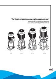
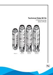
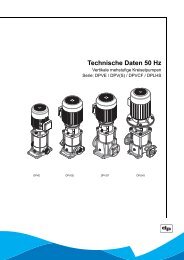
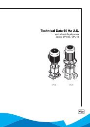
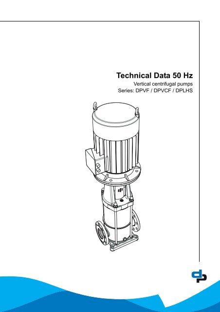
<strong>Technical</strong> <strong>Data</strong> <strong>50</strong> <strong>Hz</strong><br />
Vertical centrifugal <strong>pumps</strong><br />
Series: <strong>DP</strong>VF / <strong>DP</strong>VCF / <strong>DP</strong>LHS
2<br />
Table of Contents<br />
1 Pump introduction<br />
1.1 General .................................................................................................................................................. 4<br />
1.2 Model key............................................................................................................................................... 4<br />
1.3 Description of the product ...................................................................................................................... 5<br />
1.4 Operation ............................................................................................................................................... 5<br />
1.5 Working range........................................................................................................................................ 5<br />
2 Performance characteristics<br />
2.1 Performance curve details ..................................................................................................................... 7<br />
2.2 Performance with variable frequency drive............................................................................................ 8<br />
3 <strong>Technical</strong> specifications<br />
3.1 Dimensions and weights <strong>DP</strong>V(S)F 24 <strong>50</strong> <strong>Hz</strong> ....................................................................................... 10<br />
3.2 Hydraulic performance <strong>DP</strong>V(S)F 24 <strong>50</strong> <strong>Hz</strong> ~14<strong>50</strong> 1/min ......................................................................11<br />
3.3 Dimensions and weights <strong>DP</strong>V(S)F 32 <strong>50</strong> <strong>Hz</strong> ....................................................................................... 12<br />
3.4 Hydraulic performance <strong>DP</strong>V(S)F 32 <strong>50</strong> <strong>Hz</strong> ~2900 1/min ..................................................................... 13<br />
3.5 Dimensions and weights <strong>DP</strong>V(S)F 45 <strong>50</strong> <strong>Hz</strong> ....................................................................................... 14<br />
3.6 Hydraulic performance <strong>DP</strong>V(S)F 45 <strong>50</strong> <strong>Hz</strong> ~2900 1/min ..................................................................... 15<br />
3.7 Dimensions and weights <strong>DP</strong>V(S)F 65 <strong>50</strong> <strong>Hz</strong> ....................................................................................... 16<br />
3.8 Hydraulic performance <strong>DP</strong>V(S)F 65 <strong>50</strong> <strong>Hz</strong> ~2900 1/min ..................................................................... 17<br />
3.9 Dimensions and weights <strong>DP</strong>LHS 6 <strong>50</strong> <strong>Hz</strong>............................................................................................ 18<br />
3.10 Hydraulic performance <strong>DP</strong>LHS 6 <strong>50</strong> <strong>Hz</strong> ~2900 1/min.......................................................................... 19<br />
3.11 Dimensions and weights <strong>DP</strong>VCF 32 <strong>50</strong> <strong>Hz</strong> ......................................................................................... 20<br />
3.12 Hydraulic performance <strong>DP</strong>VCF 32 <strong>50</strong> <strong>Hz</strong> ~2900 1/min ....................................................................... 21<br />
3.13 Dimensions and weights <strong>DP</strong>VCF 45 <strong>50</strong> <strong>Hz</strong> ......................................................................................... 22<br />
3.14 Hydraulic performance <strong>DP</strong>VCF 45 <strong>50</strong> <strong>Hz</strong> ~2900 1/min ....................................................................... 23<br />
3.15 Dimensions and weights <strong>DP</strong>VCF 65 <strong>50</strong> <strong>Hz</strong> ......................................................................................... 24<br />
3.16 Hydraulic performance <strong>DP</strong>VCF 65 <strong>50</strong> <strong>Hz</strong> ~2900 1/min ....................................................................... 25<br />
4 Motors and motor options<br />
4.1 General ................................................................................................................................................ 26<br />
4.2 Options................................................................................................................................................. 26<br />
4.3 Standard motor data ............................................................................................................................ 27<br />
5 Materials<br />
5.1 Overview of materials .......................................................................................................................... 29<br />
5.2 Materials conversion ............................................................................................................................ 29<br />
5.3 Mechanical seal specifications............................................................................................................. 30<br />
6 Connections<br />
6.1 Suction and discharge connections (standard G and DIN).................................................................. 31<br />
6.2 Suction and discharge connections (optional ASME) .......................................................................... 31<br />
6.3 Suction and discharge connections (optional Rc and JIS)................................................................... 32<br />
7 Factory options<br />
7.1 Factory options .................................................................................................................................... 33<br />
8 Accessories<br />
8.1 Horizontal mounting kit ........................................................................................................................ 34
8.2 Thrust bearing housing ........................................................................................................................ 35<br />
9 Sectional drawings<br />
9.1 Parts list ............................................................................................................................................... 36<br />
9.2 Sectional drawing <strong>DP</strong>V(S)F 24/32 ....................................................................................................... 37<br />
9.3 Sectional drawing <strong>DP</strong>V(S)F 24/32 with cartridge seal ......................................................................... 38<br />
9.4 Sectional drawing <strong>DP</strong>V(S)F 45 ............................................................................................................ 39<br />
9.5 Sectional drawing <strong>DP</strong>V(S)F 45 with cartridge seal .............................................................................. 40<br />
9.6 Sectional drawing <strong>DP</strong>V(S)F 65 ............................................................................................................ 41<br />
9.7 Sectional drawing <strong>DP</strong>LHS 6................................................................................................................. 42<br />
9.8 Sectional drawing <strong>DP</strong>VCF 32 .............................................................................................................. 43<br />
9.9 Sectional drawing <strong>DP</strong>VCF 32 with cartridge seal ................................................................................ 44<br />
9.10 Sectional drawing <strong>DP</strong>VCF 45 .............................................................................................................. 45<br />
9.11 Sectional drawing <strong>DP</strong>VCF 45 with cartridge seal ................................................................................ 46<br />
9.12 Sectional drawing <strong>DP</strong>VCF 65 .............................................................................................................. 47<br />
3
4<br />
1 Pump introduction<br />
1.1 General<br />
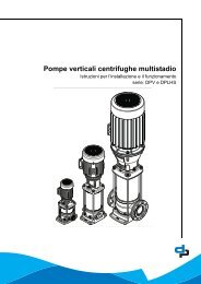
Figure 1: The vertical, multi-stage centrifugal <strong>pumps</strong>, <strong>DP</strong>V(S)F, <strong>DP</strong>VCF and <strong>DP</strong>LHS are produced by<br />
<strong>DP</strong>-Pumps.<br />
1.2 Model key<br />
Pump type <strong>DP</strong>VS F 45 -<strong>50</strong> -1<br />
Materials <strong>DP</strong>V <strong>DP</strong> Vertical <strong>pumps</strong> in AISI 304 (1.4301).<br />
<strong>DP</strong>VS <strong>DP</strong> Vertical pump in superior grade AISI 316 (1.4401).<br />
<strong>DP</strong>LHS <strong>DP</strong> Vertical pump in superior grade AISI 316 (1.4401) 40 Bar.<br />
<strong>DP</strong>VCF <strong>DP</strong> Vertical pump with cast-iron pumpcasing for heavy duty applications.<br />
Pump connections F Round flanges DIN, JIS or ASME.<br />
Model / flow 45 Pump model indicates nominal flow in [m 3 /h].<br />
Stages / head -<strong>50</strong> Indicates number of impeller stages (<strong>50</strong> = 5).<br />
Half stage impeller -1 Fitted with a half stage impeller (only <strong>DP</strong>V(S)F 45
1.3 Description of the product<br />
The vertical, single or multistage pump series <strong>DP</strong>VF,<br />
<strong>DP</strong>LHS and <strong>DP</strong>VCF are designed for pumping clean,<br />
watery liquids. Suction and discharge of the pump are<br />
in-line, making the pump easy to install. The hydraulic<br />
assembly is installed vertically and driven by an<br />
electric motor.<br />
All hydraulic parts of the pump (except for the suction/<br />
discharge casing of the <strong>DP</strong>VCF) are made of<br />
stainless steel, making the pump light and extremely<br />
suitable for applications that demand high grade<br />
materials, such as drinking water applications.<br />
The <strong>DP</strong>V series is the standard vertical pump,<br />
available in various types. The is a compact vertical<br />
pump with a built-in non-return valve, especially<br />
designed for drinking water applications. The <strong>DP</strong>LHS<br />
is designed for high pressures (up to 40 Bar) and the<br />
<strong>DP</strong>VCF is designed for industrial, heavy duty<br />
applications, such as boiler feed.<br />
The pump is initially designed for vertical installation,<br />
but can be installed horizontally by using a special<br />
adaptation set.<br />
1.4 Operation<br />
The liquid is sucked in through the pump inlet (A) on<br />
the supply side under minimum pressure. The pump<br />
increases the pressure. The liquid leaves the pump<br />
through the pump outlet (B) on the delivery side under<br />
increased pressure.<br />
C<br />
A<br />
A Pump inlet<br />
B Pump outlet<br />
C Terminal box<br />
D Fill plug/air relief plug<br />
E Drain plug<br />
D<br />
B E<br />
A<br />
1.5 Working range<br />
The working range of the <strong>pumps</strong> in this series can be<br />
summarised as follows:<br />
Table 1: Specification of the working range<br />
Pump type<br />
Ambient temperature<br />
[°C]<br />
Liquid temperature<br />
[°C]<br />
Maximum working<br />
pressure [bar]<br />
Allowable size of<br />
solids pumped<br />
Minimum supply<br />
pressure<br />
Viscosity liquid<br />
[cSt]<br />
Density liquid [kg/<br />
m 3 ]<br />
<strong>DP</strong>VF<br />
-15 to<br />
100 1<br />
<strong>DP</strong>VSF<br />
-15 to<br />
120 2<br />
25 4<br />
<strong>DP</strong>VCF<br />
+4 to 40<br />
-15 to<br />
120<br />
5µ to 1mm<br />
Not cavitating 4 .<br />
<strong>DP</strong>LHS<br />
-15 to<br />
80 3<br />
40 4<br />
1<br />
A higher viscosity may require more<br />
motor power. 5<br />
1000<br />
A higher density may require more<br />
motor power. 5<br />
Cooling The space above the cooling fan of the<br />
motor must at least be equal to 1/4 of<br />
the diameter of the inlet of the cooling<br />
fan of the motor in order to have a sufficient<br />
supply of air.<br />
Number of starts Related to the motor 5<br />
Minimum fre-<br />
10<br />
quency [<strong>Hz</strong>]<br />
Maximum fre-<br />
60<br />
quency [<strong>Hz</strong>]<br />
6<br />
1. Using the factory option “o-ring sealing EPDM E425”<br />
the max. temp. limit is 120°C.<br />
2. When pumping water, the max. allowable liquid temp is<br />
80°C.<br />
3. Higher temperatures are possible at lower pressure.<br />
For specific limits consult your supplier.<br />
4. Contact your supplier for more detailed advice.<br />
B<br />
5
6<br />
5. For standard motors see the technical specifications.<br />
When the pump is fitted with another motor brand,<br />
please consult the motor supplier.<br />
6. Pumps that are intended for <strong>50</strong> <strong>Hz</strong> operation, may not<br />
be connected to 60 <strong>Hz</strong>.<br />
Q [%]<br />
30<br />
25<br />
20<br />
15<br />
10<br />
5<br />
0<br />
40 <strong>50</strong> 60 70 80 90 100 110 120<br />
Figure 2: Minimum volume flows (Q) in% of Q<br />
optimum temperatures (t).<br />
Table 2: Minimum volume flows (Q min )<br />
<strong>DP</strong> <strong>50</strong> <strong>Hz</strong><br />
Qmin in m 3 /h<br />
6 0.8<br />
24 2,2<br />
32 4.0<br />
45 4.6<br />
65 6.1<br />
Table 3: Specific applications<br />
type application area<br />
<strong>DP</strong>VF (Drinking) water supply systems, irrigation<br />
systems, water treatment systems, carwash<br />
systems, sprinkler systems.<br />
<strong>DP</strong>VSF Water-supply systems for drinking water,<br />
softened and demineralised water, systems<br />
for brackish water, sea water and swimming-pool<br />
water, however limited with<br />
respect to temperature, pressure and chlorine<br />
percentage.<br />
<strong>DP</strong>VCF Systems for boiler supply and discharge of<br />
condensed water<br />
<strong>DP</strong>LHS Reverse osmosis installations and high<br />
pressure cleaning systems.<br />
t [°C]
2 Performance characteristics<br />
2.1 Performance curve details<br />
The preceding diagrams give a global overview of all<br />
the pump models mentioned in this documentation.<br />
Detailed characteristics are given for each model<br />
showing the hydraulic efficiency, NPSH req , and shaft<br />
power as well.<br />
The performance of the pump depends on the<br />
number of stages. The number of stages are shown<br />
as a multiple of 10, as per example:<br />
<strong>DP</strong>VF 24-60 6 full stage impellers<br />
<strong>DP</strong>VF 45-<strong>50</strong>-1 5 full stage impellers and 1 half stage<br />
impeller<br />
The detailed performance curves are in accordance<br />
with ISO 9906 Annex A. Vibration limits at rated<br />
speed and rated flow are according to ISO 9905.<br />
The motors used for the measurements are standard<br />
<strong>DP</strong>. When using another motor brand the<br />
performance data, like Q/H, efficiency and shaft<br />
power must be corrected accordingly.<br />
The characteristics given are based on:<br />
• De-aerated water at a temperature of 20 °C<br />
• Density of 1 kg/dm 3<br />
• Kinematical viscosity of 1 mm 2 /s (1 cst)<br />
To prevent the pump from overheating, gathering gas,<br />
cavitation etc. a minimum flow has to be secured.<br />
The minimum flow corresponds to a percentage of<br />
the optimum flow Q opt in relation to the temperature of<br />
the liquid pumped.<br />
7
8<br />
2.2 Performance with variable<br />
frequency drive<br />
The minimum frequency of the <strong>DP</strong> motor should be<br />
limited to 10 <strong>Hz</strong> to ensure sufficient cooling. When the<br />
rotational speed exceeds the nominal speed of the<br />
motor, make sure that the power output of the motor<br />
is suitable to drive the corresponding pump model.<br />
ID3238<br />
H<br />
�<br />
hydr.<br />
P/st.<br />
NPSH<br />
req.<br />
n2<br />
n2<br />
n2<br />
n2<br />
The performance of the pump differs from the fixed<br />
speed performance according to the recalculation<br />
scheme.<br />
2<br />
Q2 � �<br />
n1<br />
Q1 Q2<br />
Q<br />
Figure 3: Performance characteristics 3238/08072008<br />
n1<br />
n1<br />
n1<br />
n1<br />
Q<br />
Q<br />
Q<br />
2<br />
2<br />
n<br />
�n2� �n� Q<br />
�n2� �n� H � � H<br />
3<br />
3<br />
1<br />
1<br />
P � � P<br />
2<br />
1<br />
2<br />
2<br />
� �<br />
�n1� 1��<br />
1 �<br />
�n� 0.<br />
1<br />
�<br />
�<br />
� � � �<br />
�<br />
2 1<br />
�<br />
0.<br />
1 �<br />
��<br />
�<br />
2 �<br />
1<br />
�n2� �n� NPSH � � NPSH<br />
2<br />
1<br />
2<br />
1<br />
1
10<br />
3 <strong>Technical</strong> specifications<br />
3.1 Dimensions and weights <strong>DP</strong>V(S)F 24 <strong>50</strong> <strong>Hz</strong><br />
ID 2734/05122005<br />
<strong>DP</strong>V(S)F 24 20010205<br />
<strong>DP</strong>V(S)F 24 <strong>50</strong> <strong>Hz</strong> General<br />
Model<br />
P [kW]<br />
E1 [mm] 1<br />
E2 [mm]<br />
F1 [mm]<br />
F2 [mm]<br />
Net weight<br />
[kg]<br />
24- 10 1,1 176 136 738 458 57<br />
24- 20 1,1 176 136 786 <strong>50</strong>6 59<br />
24- 30 1,5 176 136 835 555 64<br />
24- 40 2,2 194 147 919 603 75<br />
24- <strong>50</strong> 2,2 194 147 968 652 77<br />
24- 60 3 194 147 1016 700 81<br />
24- 70 3 194 147 1065 749 83<br />
24- 80 4 233 162 1121 797 93<br />
24- 90 4 233 162 1170 846 96<br />
24- 100 5,5 266 179 1297 914 131<br />
24- 110 5,5 266 179 1346 963 134<br />
24- 120 5,5 266 179 1394 1011 136<br />
24- 160 7,5 266 179 1626 1205 155<br />
20000569-E<br />
1. Diameter adapter flange 5,5-7,5 kW = 300 mm, 11-22 kW = 3<strong>50</strong> mm,<br />
30-37 kW = 400 mm
3.2 Hydraulic performance <strong>DP</strong>V(S)F 24 <strong>50</strong> <strong>Hz</strong> ∼14<strong>50</strong> 1/min<br />
ID 2709/15102007<br />
20000553-D<br />
11
12<br />
3.3 Dimensions and weights <strong>DP</strong>V(S)F 32 <strong>50</strong> <strong>Hz</strong><br />
ID 2734/05122005<br />
<strong>DP</strong>V(S)F 32 20010205<br />
<strong>DP</strong>V(S)F 32 <strong>50</strong> <strong>Hz</strong> General<br />
Model<br />
P [kW]<br />
E1 [mm] 1<br />
E2 [mm]<br />
F1 [mm]<br />
F2 [mm]<br />
Net weight<br />
[kg]<br />
32- 10 2,2 176 136 733 458 61<br />
32- 20 4 233 162 830 <strong>50</strong>6 81<br />
32- 30 5,5 233 162 904 575 89<br />
32- 40 7,5 233 162 980 623 96<br />
32- <strong>50</strong> 11 315 206 1279 777 167<br />
32- 60 11 315 206 1327 825 169<br />
32- 70 15 315 206 1376 874 186<br />
32- 80 15 315 206 1424 922 188<br />
32- 90 18,5 315 206 1517 971 205<br />
32- 100 18,5 315 206 1565 1019 208<br />
32- 110 18,5 315 206 1614 1068 210<br />
32- 120 22 3<strong>50</strong> 225 1711 1116 248<br />
20000600-I<br />
1. Diameter adapter flange 5,5-7,5 kW = 300 mm, 11-22 kW = 3<strong>50</strong> mm,<br />
30-37 kW = 400 mm
3.4 Hydraulic performance <strong>DP</strong>V(S)F 32 <strong>50</strong> <strong>Hz</strong> ∼2900 1/min<br />
2711<br />
20000574-F<br />
13
14<br />
3.5 Dimensions and weights <strong>DP</strong>V(S)F 45 <strong>50</strong> <strong>Hz</strong><br />
ID2735/05122005<br />
<strong>DP</strong>V(S)F 45 20010207<br />
<strong>DP</strong>V(S)F 45 <strong>50</strong> <strong>Hz</strong> General<br />
Model<br />
P [kW]<br />
E1 [mm] 1<br />
E2 [mm]<br />
F1 [mm]<br />
F2 [mm]<br />
Net weight<br />
[kg]<br />
45- 10-1 2,2 176 136 733 458 62<br />
45- 10 4 233 162 782 458 80<br />
45- 20-1 5,5 233 162 855 526 88<br />
45- 20 7,5 233 162 883 526 92<br />
45- 30-1 11 315 206 1182 680 164<br />
45- 30 11 315 206 1182 680 164<br />
45- 40-1 11 315 206 1230 728 166<br />
45- 40 15 315 206 1230 728 180<br />
45- <strong>50</strong>-1 15 315 206 1279 777 182<br />
45- <strong>50</strong> 18,5 315 206 1323 777 198<br />
45- 60-1 18,5 315 206 1371 825 200<br />
45- 60 22 3<strong>50</strong> 225 1420 825 236<br />
45- 70-1 22 3<strong>50</strong> 225 1469 874 238<br />
45- 70 30 400 290 1524 874 311<br />
45- 80-1 30 400 290 1572 922 314<br />
45- 80 30 400 290 1572 922 314<br />
45- 90-1 30 400 290 1621 971 316<br />
45- 90 37 400 290 1621 971 330<br />
45- 100-1 37 400 290 1669 1019 332<br />
45- 100 37 400 290 1669 1019 332<br />
20000631-J<br />
1. Diameter adapter flange 5,5-7,5 kW = 300 mm, 11-22 kW = 3<strong>50</strong> mm,<br />
30-37 kW = 400 mm
3.6 Hydraulic performance <strong>DP</strong>V(S)F 45 <strong>50</strong> <strong>Hz</strong> ∼2900 1/min<br />
ID 2713/26032007<br />
20000605-G<br />
15
16<br />
3.7 Dimensions and weights <strong>DP</strong>V(S)F 65 <strong>50</strong> <strong>Hz</strong><br />
ID 2761/07062006<br />
<strong>DP</strong>V(S)F 65 99000288-D<br />
<strong>DP</strong>V(S)F 65 <strong>50</strong> <strong>Hz</strong> General<br />
Model<br />
P [kW]<br />
E1 [mm] 1<br />
E2 [mm]<br />
F1 [mm]<br />
F2 [mm]<br />
Net weight<br />
[kg]<br />
65- 10 3 194 147 886 570 78<br />
65- 20 5,5 233 162 1008 679 97<br />
65- 30 11 315 206 1300 798 104<br />
65- 40 11 315 206 1389 887 173<br />
65- <strong>50</strong> 15 315 206 1478 976 191<br />
65- 60 15 315 206 1567 1065 194<br />
65- 70 18,5 315 206 1700 1154 213<br />
65- 80 22 3<strong>50</strong> 225 1838 1243 252<br />
65- 90 30 400 290 1982 1332 255<br />
99000286-I<br />
1. Diameter adapter flange 5,5-7,5 kW = 300 mm, 11-22 kW = 3<strong>50</strong> mm,<br />
30-37 kW = 400 mm
3.8 Hydraulic performance <strong>DP</strong>V(S)F 65 <strong>50</strong> <strong>Hz</strong> ∼2900 1/min<br />
ID2715<br />
99000102-F<br />
17
18<br />
3.9 Dimensions and weights <strong>DP</strong>LHS 6 <strong>50</strong> <strong>Hz</strong><br />
ID 2740/05122005<br />
<strong>DP</strong>LHS 6 94001301<br />
<strong>DP</strong>LHS 6 <strong>50</strong> <strong>Hz</strong> General<br />
Model<br />
P [kW]<br />
E1 [mm] 1<br />
E2 [mm]<br />
F1 [mm]<br />
F2 [mm]<br />
Net weight<br />
[kg]<br />
6-<strong>50</strong> 4 233 162 753 429 79<br />
6-70 4 233 162 813 489 82<br />
6-80 4 233 162 843 519 83<br />
6- 100 5,5 233 162 928 599 92<br />
6- 120 7,5 233 162 1015 658 99<br />
6- 140 11 315 206 12<strong>50</strong> 748 166<br />
6- 160 11 315 206 1310 808 171<br />
6- 180 11 315 206 1369 867 174<br />
6- 200 15 315 206 1429 927 191<br />
9<strong>50</strong>00234-H<br />
1. Diameter adapter flange 5,5-7,5 kW = 300 mm, 11-22 kW = 3<strong>50</strong> mm,<br />
30-37 kW = 400 mm
3.10 Hydraulic performance <strong>DP</strong>LHS 6 <strong>50</strong> <strong>Hz</strong> ∼2900 1/min<br />
2697<br />
94001143-G<br />
19
20<br />
3.11 Dimensions and weights <strong>DP</strong>VCF 32 <strong>50</strong> <strong>Hz</strong><br />
2919/1<strong>50</strong>52007<br />
<strong>DP</strong>VCF 32 20070258-A<br />
<strong>DP</strong>VCF 32 <strong>50</strong> <strong>Hz</strong> General<br />
Model<br />
P [kW]<br />
E1 [mm] 1<br />
E2 [mm]<br />
F1 [mm]<br />
F2 [mm]<br />
Net weight<br />
[kg]<br />
32-10 2,2 176 136 733 458 x<br />
32- 20 4 233 162 830 <strong>50</strong>6 87<br />
32- 30 5,5 233 162 904 575 95<br />
32- 40 7,5 233 162 980 623 101<br />
32- <strong>50</strong> 11 315 206 1279 777 173<br />
32- 60 11 315 206 1327 825 175<br />
32- 70 15 315 206 1376 874 191<br />
32- 80 15 315 206 1424 922 194<br />
32- 90 18,5 315 206 1473 971 196<br />
32- 100 18,5 315 206 1565 1019 213<br />
32- 110 18,5 315 206 1614 1068 215<br />
32- 120 22 3<strong>50</strong> 225 1711 1116 254<br />
20000600-I<br />
1. Diameter adapter flange 5,5-7,5 kW = 300 mm, 11-22 kW = 3<strong>50</strong> mm,<br />
30-37 kW = 400 mm
3.12 Hydraulic performance <strong>DP</strong>VCF 32 <strong>50</strong> <strong>Hz</strong> ∼2900 1/min<br />
ID2921<br />
20070244-B<br />
21
22<br />
3.13 Dimensions and weights <strong>DP</strong>VCF 45 <strong>50</strong> <strong>Hz</strong><br />
2920/1<strong>50</strong>52007<br />
<strong>DP</strong>VCF 45 20070259-A<br />
<strong>DP</strong>VCF 45 <strong>50</strong> <strong>Hz</strong> General<br />
Model<br />
P [kW]<br />
E1 [mm] 1<br />
E2 [mm]<br />
F1 [mm]<br />
F2 [mm]<br />
Net weight<br />
[kg]<br />
45- 20-1 5,5 233 162 855 526 96<br />
45- 20 7,5 233 162 883 526 100<br />
45- 30-1 11 315 206 1182 680 172<br />
45- 30 11 315 206 1182 680 172<br />
45- 40-1 11 315 206 1230 728 174<br />
45- 40 15 315 206 1230 728 188<br />
45- <strong>50</strong>-1 15 315 206 1279 777 190<br />
45- <strong>50</strong> 18,5 315 206 1323 777 206<br />
45- 60-1 18,5 315 206 1371 825 208<br />
45- 60 22 3<strong>50</strong> 225 1420 825 244<br />
45- 70-1 22 3<strong>50</strong> 225 1469 874 246<br />
45- 70 30 400 290 1524 874 319<br />
45- 80-1 30 400 290 1572 922 322<br />
45- 80 30 400 290 1572 922 322<br />
45- 90-1 30 400 290 1621 971 324<br />
45- 90 37 400 290 1621 971 338<br />
45- 100-1 37 400 290 1669 1019 340<br />
45- 100 37 400 290 1669 1019 340<br />
20000631-J<br />
1. Diameter adapter flange 5,5-7,5 kW = 300 mm, 11-22 kW = 3<strong>50</strong> mm,<br />
30-37 kW = 400 mm
3.14 Hydraulic performance <strong>DP</strong>VCF 45 <strong>50</strong> <strong>Hz</strong> ∼2900 1/min<br />
ID 2922/06042007<br />
20070245-A<br />
23
24<br />
3.15 Dimensions and weights <strong>DP</strong>VCF 65 <strong>50</strong> <strong>Hz</strong><br />
ID 2733/05122005<br />
<strong>DP</strong>VCF 65 20010103<br />
<strong>DP</strong>VCF 65 <strong>50</strong> <strong>Hz</strong> General<br />
Model<br />
P [kW]<br />
E1 [mm] 1<br />
E2 [mm]<br />
F1 [mm]<br />
F2 [mm]<br />
Net weight<br />
[kg]<br />
65- 10 3 194 147 961 645 83<br />
65- 20 5,5 233 162 1083 754 102<br />
65- 30 11 233 162 1200 843 109<br />
65- 40 11 315 206 1464 962 178<br />
65- <strong>50</strong> 15 315 206 1553 1051 196<br />
65- 60 15 315 206 1642 1140 199<br />
65- 70 18,5 315 206 1775 1229 218<br />
65- 80 22 3<strong>50</strong> 225 1913 1318 257<br />
65- 90 30 3<strong>50</strong> 225 2002 1407 260<br />
99000286-H<br />
1. Diameter adapter flange 5,5-7,5 kW = 300 mm, 11-22 kW = 3<strong>50</strong> mm,<br />
30-37 kW = 400 mm
3.16 Hydraulic performance <strong>DP</strong>VCF 65 <strong>50</strong> <strong>Hz</strong> ∼2900 1/min<br />
2725<br />
200<strong>50</strong>466-B<br />
25
26<br />
4 Motors and motor options<br />
4.1 General<br />
The standard <strong>DP</strong>motors are produced conform the<br />
latest technical design, and comply with the<br />
international standards and EU directives regarding<br />
safety measures.<br />
The motors can be specified as:<br />
• Standard IE2 >= 1,5kW<br />
• T.E.F.C. (totally enclosed fan cooled) Squirrel<br />
cage.<br />
• AC induction motor.<br />
• Protection IP55.<br />
• Insulation class F.<br />
• Temperature rise class B.<br />
• Duty class S1, maximum 20 starts per hour.<br />
• Noise levels conform IEC 60034-9.<br />
• > 2,2 kW standard 3 x PTC.<br />
The motors come in 3 different configurations.<br />
Mounting in acc. with IEC60034-7 and dimensions in<br />
acc. with IEC 60072-1<br />
ID3442<br />
V18 flange V1 flange close coupled<br />
4.2 Options<br />
• Standard motors as per above, in single phase<br />
(1x230V) max 2,2 kW.<br />
• Provided with 10 pole industrial connector<br />
“Harting stecker” HAN 10, mounted in stead of<br />
the motor connection box,
4.3 Standard motor data<br />
Table 4: Motor data 1 and 3 phase, 2p <strong>50</strong> <strong>Hz</strong><br />
Article number<br />
Rated power output [kW]<br />
Rated Voltage [V]<br />
Rated current [A]<br />
Table 5: Motor data 3 phase, 4p <strong>50</strong> <strong>Hz</strong><br />
Starting current Ia/In<br />
Cos Phi<br />
3700000022 2,2 1x230 13,04 4,8 0,95 10% 2800 77 58 1xM20x1,5 20<br />
3710011022 2,2 230/400 8,2/4,7 7,3 0,81 10% 2870 83,5 56 1xM20x1,5 30<br />
3710111030 3 230/400 10,2/6,2 8,3 0,83 10% 2900 84,6 58 2xM20x1,5 30<br />
3710112030 3 400/690 6,2/3,7 8,3 0,83 10% 2900 84,6 58 2xM20x1,5 30<br />
3710111040 4 230/400 13,4/7,7 8,5 0,87 10% 2915 86,3 59 2xM20x1,5 30<br />
3710112040 4 400/690 7,7/4,5 8,5 0,87 10% 2915 86,3 59 2xM20x1,5 30<br />
3710111055 5,5 230/400 17,5/10,1 8,8 0,9 10% 2930 87,5 64 2xM25x1,5 20<br />
3700112055 5,5 400/690 10,1/5,9 8,8 0,9 10% 2930 87,5 64 2xM25x1,5 20<br />
3710111075 7,5 230/400 22,9/13,2 8,5 0,92 10% 2920 88,6 64 2xM25x1,5 20<br />
3710112075 7,5 400/690 13,2/7,7 8,5 0,92 10% 2920 88,6 64 2xM25x1,5 20<br />
3710111110 11 230/400 36,5/21,0 7,8 0,84 10% 29<strong>50</strong> 90 71 2xM32x1,5 15<br />
3710112110 11 400/690 21,0/12,2 7,8 0,84 10% 29<strong>50</strong> 90 71 2xM32x1,5 15<br />
37101111<strong>50</strong> 15 230/400 49,0/28,2 7,6 0,85 10% 2945 90,3 70 2xM32x1,5 15<br />
37101121<strong>50</strong> 15 400/690 28,2/16,3 7,6 0,85 10% 2945 90,3 70 2xM32x1,5 15<br />
3710111185 18,5 230/400 58,5/33,6 9,3 0,87 10% 29<strong>50</strong> 91,3 73 2xM32x1,5 15<br />
3710112185 18,5 400/690 33,6/16,5 9,3 0,87 10% 29<strong>50</strong> 91,3 73 2xM32x1,5 15<br />
3710111220 22 230/400 68,7/39,5 7,5 0,88 10% 2945 91,3 75 2xM32x1,5 12<br />
3710112220 22 400/690 39,5/22,4 7,5 0,88 10% 2945 91,3 75 2xM32x1,5 12<br />
3700111300 30 230/400 89,7/51,8 7,5 0,91 10% 2955 92,9 80 2xM<strong>50</strong>x1,5 12<br />
3700112300 30 400/690 51,8/29,9 7,5 0,91 10% 2955 92,9 80 2xM<strong>50</strong>x1,5 12<br />
3700111370 37 230/400 110/63,5 7,5 0,91 10% 2957 93,3 80 2xM<strong>50</strong>x1,5 20<br />
3700112370 37 400/690 63,5/36,7 7,5 0,91 10% 29<strong>50</strong> 93,3 80 2xM<strong>50</strong>x1,5 12<br />
37001114<strong>50</strong> 45 230/400 131,6/76 7,5 0,91 10% 2969 93,7 80 2xM<strong>50</strong>x1,5 20<br />
37001124<strong>50</strong> 45 400/690 76/43,9 7,5 0,91 10% 2969 93,7 80 2xM<strong>50</strong>x1,5 12<br />
Article number<br />
Rated power output [kW]<br />
Rated Voltage [V]<br />
Rated current [A]<br />
Starting current Ia/In<br />
Cos Phi<br />
3710031011 1,1 230/400 4,5/2,6 5,7 0,76 10% 1425 76 <strong>50</strong> 1xM20x1,5 30<br />
3710031015 1,5 230/400 6,0/3,4 6,0 0,76 10% 1425 82,8 <strong>50</strong> 1xM20x1,5 30<br />
3710031022 2,2 230/400 7,9/4,5 7,3 0,83 10% 1440 84,7 55 1xM20x1,5 30<br />
3710132030 3 400/690 6,8/3,9 7,0 0,75 10% 1445 85,5 64 2xM20x1,5 30<br />
3710132040 4 400/690 8,4,/4,9 6,7 0,79 10% 14<strong>50</strong> 87,0 64 2xM20x1,5 30<br />
3700132055 5,5 400/690 11,3/6,5 7,9 0,8 10% 1460 88,0 64 2xM25x1,5 20<br />
3710132075 7,5 400/690 15,3/8,2 7,5 0,86 10% 1460 88,7 64 2xM25x1,5 20<br />
Tolerance rated voltage<br />
Tolerance rated voltage<br />
Rated speed [rpm]<br />
Rated speed [rpm]<br />
Motor efficiency<br />
Motor efficiency<br />
Sound pressure [dB(A)]<br />
Sound pressure [dB(A)]<br />
Cable gland<br />
Cable gland<br />
Max. starts per hour<br />
Starts per hour<br />
27
28<br />
ID 3430<br />
Figure 4: Motor exploded view
5 Materials<br />
5.1 Overview of materials<br />
Pos. nr. Description <strong>DP</strong>VF <strong>DP</strong>VSF <strong>DP</strong>VCF <strong>DP</strong>LHS<br />
101 Pump casing 1.4301 1.4404 JL 1040 1.4408<br />
108 Stage casing 1.4301 1.4404 1.4301 1.4404<br />
160 Cover 1.4301 1.4404 1.4301 1.4404<br />
171 Diffuser - 1.4404 1.4301 -<br />
10-6 Pump shroud 1.4301 1.4404 1.4301 1.4404<br />
210 Shaft 1.4305 1.4401 1.4305 1.4401<br />
230 Impeller 1.4301 1.4404 1.4301 1.4404<br />
341 Motor stool JL 1040 1.4408<br />
412 O-ring EPDM Viton EPDM E425 Viton<br />
525 Spacer sleeve 1.4301 1.4401 1.4301 1.4404<br />
529 Bearing sleeve Tungsten-carbide<br />
1<br />
) Bearing Ceramic<br />
890 Base plate JL 1040 -<br />
903 Vent plug Brass AISI316 AISI316<br />
905 Tie bolt 1.4057<br />
913 Vent plug AISI913<br />
920 Nut 1.4301 1.4404 1.4301 1.4404<br />
932 Circlip 1.4571<br />
1. The bearing has no pos.nr. because it is a fixed part of the stage casing (108) or diffuser (171)<br />
5.2 Materials conversion<br />
Material Description Code and material nr. Standard ASTM / AISI 1<br />
JL 1040 Cast iron GJL-2<strong>50</strong> EN 1561 A48:40B<br />
1.4301 Chromium-nickel steel X5CrNi18-10 EN 10088 A276:304<br />
1.4404 Chromium-nickel-molybdenum steel X2CrNiMo 17-12-2 EN 10088 A276:316L<br />
1.4408 Chromium-nickel-molybdenum cast steel GX5CrNiMo 19-11-2 EN 10213 A743CF8M<br />
1.4571 Chromium-nickel-molybdenum steel X6CrNiMoTi17-12-2 EN 10088 A276:316Ti<br />
1.4057 Chromium-nickel steel X17CrNi16-2--QT800 EN 10088-3 A276:431<br />
1.4305 Chromium-nickel steel X8CrNiS 18-9 EN 10088 A276:303<br />
1.4401 Chromium-nickel-molybdenum steel X5CrNiMo 17-12-2 EN 10088 A276:316<br />
1.4308 Chromium-nickel cast steel GX5CrNi 19-10 EN 10283 A743:CF8<br />
1.4460 Chromium-nickel-molybdenum steel X3CrNiMoN 27 5 2 EN 10088 --:329<br />
1. Note: The indication of the material designations to ASTM / AISI is not binding<br />
29
30<br />
5.3 Mechanical seal specifications<br />
Pump series <strong>DP</strong>V(F) <strong>DP</strong>VS(F) <strong>DP</strong>VCF <strong>DP</strong>VF 24, 32,<br />
45 > 7,5 kW<br />
<strong>DP</strong>VF 65<br />
Mechanical<br />
seal type<br />
<strong>DP</strong>VSF 24,<br />
32, 45 > 7,5<br />
kW<br />
<strong>DP</strong>VSF 65<br />
Max. pressure 1000 kPa 1000 kPa 1000 kPa 1000 kPa<br />
Dynamic part Carbon Carbon Carbon Carbon<br />
Static part Silicon car- Silicon car-<br />
Silicon car- Silicon carbidebidebidebide<br />
Elastomer EPDM Viton EPDM Viton<br />
<strong>DP</strong>VCF 32,<br />
45 > 7,5 kW<br />
<strong>DP</strong>VCF 65<br />
Max. pressure 2<strong>50</strong>0 kPa 2<strong>50</strong>0 kPa 2<strong>50</strong>0 kPa 2<strong>50</strong>0 kPa 2<strong>50</strong>0 kPa 2<strong>50</strong>0 kPa<br />
Dynamic part Silicon carbide<br />
Silicon carbide<br />
Tungsten carbide<br />
Silicon carbide<br />
Silicon carbide<br />
Tungsten carbide<br />
Static part Carbon Carbon Carbon Carbon Carbon Carbon<br />
Elastomer EPDM Viton EPDM E425 EPDM Viton EPDM E425<br />
<strong>DP</strong>LHS 6<br />
Max. pressure 4000 kPa<br />
Dynamic part Carbon<br />
Static part Tungsten carbide<br />
Elastomer Viton
6 Connections<br />
6.1 Suction and discharge connections (standard G and DIN)<br />
Pump model key <strong>DP</strong>V(S)F <strong>DP</strong>VCF <strong>DP</strong>LHS<br />
Connection Round sliding flange Round flange ridged cast to<br />
pump casing<br />
6.2 Suction and discharge connections (optional ASME)<br />
Round flange ridged cast to<br />
pump casing<br />
Norm DIN EN 1092-2 PN 25 DIN EN 1092-2 PN25 DIN EN 1092-2 PN 40<br />
Pressure class PN 25 PN 40<br />
<strong>DP</strong>V(S)F 24 DN 65 - -<br />
<strong>DP</strong>V(S/C)F 32 DN 65 DN 65 -<br />
<strong>DP</strong>V(S/C)F 45 DN 80 DN 80 -<br />
<strong>DP</strong>V(S/C)F 65 DN 100 1<br />
DN 100 -<br />
<strong>DP</strong>LHS 6 - - DN 32<br />
1. PN 16<br />
Pump model key <strong>DP</strong>V(S)F <strong>DP</strong>LHS<br />
Connection Round sliding flange Round flange ridged cast to pump<br />
casing<br />
Norm ASME B 16.1 cl.2<strong>50</strong> ASME B 16.5 cl.600<br />
Pressure class PN40<br />
<strong>DP</strong>V(S)F 24 - -<br />
<strong>DP</strong>V(S)F 32 2½” -<br />
<strong>DP</strong>V(S)F 45 3” -<br />
<strong>DP</strong>V(S)F 65 4” 1 -<br />
<strong>DP</strong>LHS 6 - 1¼”<br />
1. class 125<br />
31
32<br />
6.3 Suction and discharge connections (optional Rc and JIS)<br />
Pump model key <strong>DP</strong>V(S)F<br />
Connection Round sliding flange<br />
Norm JIS B2238<br />
Pressure class 16 K<br />
<strong>DP</strong>V(S)F 24 JIS 65<br />
<strong>DP</strong>V(S)F 32 JIS 65<br />
<strong>DP</strong>V(S)F 45 JIS 80<br />
<strong>DP</strong>V(S)F 65 JIS 100
7 Factory options<br />
7.1 Factory options<br />
Description: Applicable model: Standard: Options<br />
Sealing:<br />
Sleeve and stage O-rings: <strong>DP</strong>V EPDM Viton<br />
<strong>DP</strong>VS Viton HNBR<br />
E425 EPDM<br />
EPDM<br />
Mechanical seal: <strong>DP</strong>V Ca/Sic/EPDM<br />
Ca/SiC/EPDM<br />
SiC/Ca/EPDM<br />
SiC/Ca/EPDM<br />
<strong>DP</strong>VS Ca/SiC/Viton<br />
Ca/SiC/Viton<br />
SiC/Ca/Viton<br />
Sic/Ca/Viton<br />
Mechanical:<br />
<strong>DP</strong>VCF Tuc/Ca/EPDM<br />
Tuc/Ca/EPDM<br />
SiC/SiC/EPDM<br />
SiC/SiC/Viton<br />
TuC/TuC/Viton<br />
TuC/TuC/HNBR<br />
Vent and drain plugs AISI 316 <strong>DP</strong>V Vent and drain plugs brass Vent and drain plugs AISI 316<br />
Safety vent plug AISI 316 All Standard vent plug Safety vent plug AISI 316<br />
Color finish All Pump and motor RAL <strong>50</strong>02 RAL 3000 (fire red)<br />
De-staging All Intermediate impeller stage Stage without impeller<br />
JIS flanges <strong>DP</strong>VF Round flange DIN PN 25 Round flange JIS PN 25<br />
ASME flanges<br />
Motor:<br />
<strong>DP</strong>VF Round flange DIN PN 25 Round flange ASME<br />
B 16.1 cl. 2<strong>50</strong><br />
Anti condensation heater 3 phase 2,2 kW - 37 kW None With anti condensation heater<br />
1~230 V<br />
Rain cover 3 phase 2,2 kW - 37 kW None Rain cover on fan hood<br />
PTC thermistors 3 phase 2,2 kW None With 3 PTC thermistors<br />
Harting stecker 3 phase 2,2 kW - 37 kW None Cable connection provided<br />
with 10-pole Harting stecker<br />
Connection box position 2,2 kW - 37 kW 9h 0h, 3h, 6h<br />
Increased motor power 2,2 kW - 30 kW Standard motor power One step higher motor power<br />
Enlarged motor lantern 2,2 kW - 30 kW Standard motor lantern Motor lantern to fit one step<br />
higher motorpower<br />
Winding configuration 3 phase 2,2 kW - 2,2 kW 230 / 400 V 400 / 692 V<br />
3 phase 3 kW - 37 kW 400 / 692 V 230 / 400 V<br />
Winding Voltage 3 phase 2,2 kW - 37 kW 400 V Y or Δ <strong>50</strong>0 V Y or Δ<br />
33
34<br />
8 Accessories<br />
8.1 Horizontal mounting kit<br />
In special applications it could be a solution to mount<br />
the pump in a horizontal position. Although the pump<br />
is designed for vertical positioning the hydraulic parts<br />
of the pump are also capable of functioning in a<br />
horizontal position. This option is limited by the motor<br />
rating. The motors of 11kW and above are equipped<br />
with a co-axial bearing which is not suitable for<br />
horizontal positioning.<br />
To ensure a proper and stable horizontal mounting<br />
position for the pump, stainless steel AISI 304<br />
support frames are available. To mount the support<br />
frames, bolts up to a maximum of M12 can be used.<br />
The horizontal mounting kit includes the following<br />
parts:<br />
• Pump bracket support<br />
• Motor flange support<br />
• 4 bolts M12<br />
• 4 washers 12mm<br />
• 4 nuts M12<br />
ID2628/30052005<br />
Motor flange support 200<strong>50</strong>451-F<br />
ID2627/30052005<br />
Pump bracket support 200<strong>50</strong>451-F<br />
8.1.1 Dimensions of <strong>pumps</strong> fitted with<br />
horizontal mounting kit<br />
Dimensions are related to the dimensions of the<br />
complete pump in standard vertical position and are<br />
mentioned in [mm].<br />
<strong>DP</strong>V(S)(F) 24 D = 137<br />
Motor [kW] Art, nr, C H A B Weight<br />
[kg]<br />
1,1 1,5 18707031 F2+47 170 210 180 4,00<br />
2,2 4 18707032 F2+39<br />
5,5 7,5 18707033 F2-17 3,90<br />
200<strong>50</strong>451-F
<strong>DP</strong>V(S)(C)F 32/45 D = 137<br />
<strong>DP</strong>V(S)(C)F 65 D = 172<br />
Motor [kW] Art, nr, C H A B Weight<br />
[kg]<br />
1,5 2,2 18707041 F2+47 170 210 180 4,00<br />
3 4 18707042 F2+39<br />
5,5 7,5 18707043 F2-17 3,90<br />
200<strong>50</strong>451-F<br />
8.2 Thrust bearing housing<br />
ID2641/11072005<br />
Thrust bearing housing 200<strong>50</strong>227-B<br />
The standard <strong>DP</strong>-Pumps motors are specially<br />
designed to drive the pump. When a standard IEC or<br />
NEMA norm motor has to be installed (or a special<br />
motor to fulfill the applications requirement, like<br />
explosion proof, high efficiency) a special bearing<br />
housing must be installed to relieve the motor of the<br />
axial force created by the pump.<br />
ATTENTION<br />
Only a motor with a standard key can be<br />
installed with a thrust bearing housing.<br />
ATTENTION<br />
There is no need to change the motor<br />
stool of the pump. The bearing flange<br />
can be mounted on the standard motor<br />
stool of the pump.<br />
8.2.1 Dimensions and weights.<br />
The total height increase of the pump will be 113,5<br />
mm / 4.47 inch. The weight of the thrust bearing<br />
housing kits are given in the table below:<br />
Table 6: weight of the thrust bearing housings kits<br />
Frame<br />
size<br />
Motorshaft<br />
Kit art. nr. Weight<br />
[kg]<br />
Weight<br />
[lbs]<br />
132 38 18708020 7,97 17.57<br />
160 42 18708021 8,25 18.19<br />
180 48 18708022 9,30 20.<strong>50</strong><br />
200 55 18708023 9,44 20.81<br />
35
36<br />
9 Sectional drawings<br />
9.1 Parts list<br />
Number (ZN) Description:<br />
101 Pump casing<br />
108 Stage casing<br />
160 Cover<br />
171 Diffuser<br />
210 Shaft<br />
230 Impeller<br />
341 Motor stool<br />
400 Gasket<br />
411 Joint ring<br />
412 O-ring<br />
433 Mechanical seal<br />
471 Seal cover<br />
<strong>50</strong>0 Ring<br />
<strong>50</strong>9 Intermediate ring<br />
525 Spacer sleeve<br />
525.08 Spacer sleeve<br />
529 Bearing sleeve<br />
554 Washer<br />
560 Pin<br />
681 Coupling guard<br />
722 Taper piece, flanged<br />
723 Flange<br />
800 Motor<br />
801 Flanged motor<br />
802 Motor for close coupling<br />
831 Fan impeller<br />
832 Fan hood<br />
833 Terminal box<br />
835 Terminal board<br />
837 Condenser<br />
862 Coupling shell<br />
890 Baseplate fabricated or cast<br />
900 Screw<br />
901 Hexagon head bolt<br />
903 Screwed plug<br />
904 Grub screw<br />
905 Tie bolt<br />
913 Vent plug<br />
914 Hexagon socket head cap scr.<br />
920 Nut<br />
930 Safety device<br />
932 Circlip<br />
10-6 Pump shroud<br />
81-37 Terminal box coverplate
9.2 Sectional drawing <strong>DP</strong>V(S)F 24/32<br />
ID 2688/05122005<br />
20010712-F<br />
37
38<br />
9.3 Sectional drawing <strong>DP</strong>V(S)F 24/32 with cartridge seal<br />
ID 2689/05122005<br />
20010713-F
9.4 Sectional drawing <strong>DP</strong>V(S)F 45<br />
ID 2690/05122005<br />
20010714-F<br />
39
40<br />
9.5 Sectional drawing <strong>DP</strong>V(S)F 45 with cartridge seal<br />
ID 2691/05122005<br />
20010715-F
9.6 Sectional drawing <strong>DP</strong>V(S)F 65<br />
ID 2687/05122005<br />
20000052-G<br />
41
42<br />
9.7 Sectional drawing <strong>DP</strong>LHS 6<br />
ID 2693/05122005<br />
20030238-C
9.8 Sectional drawing <strong>DP</strong>VCF 32<br />
ID 2926/1<strong>50</strong>52007<br />
20070217-A<br />
43
44<br />
9.9 Sectional drawing <strong>DP</strong>VCF 32 with cartridge seal<br />
ID 2927/1<strong>50</strong>52007<br />
20070218-A
9.10 Sectional drawing <strong>DP</strong>VCF 45<br />
ID 2928/1<strong>50</strong>52007<br />
20070219-A<br />
45
46<br />
9.11 Sectional drawing <strong>DP</strong>VCF 45 with cartridge seal<br />
ID 2929/1<strong>50</strong>52007<br />
20070220-A
9.12 Sectional drawing <strong>DP</strong>VCF 65<br />
ID 2695/07062006<br />
20040437-D<br />
47
dp <strong>pumps</strong><br />
P.O. Box 28<br />
2400 AA Alphen aan den Rijn<br />
The Netherlands<br />
t +31 172 48 83 88<br />
f +31 172 46 89 30<br />
dp@dp-<strong>pumps</strong>.com<br />
www.dp-<strong>pumps</strong>.com<br />
04/2011<br />
97004434-B<br />
Subject to modifications. Digital alteration, publication or distribution of the content of this document without prior notice is strictly prohibited.<br />
Permission for use, copying and distribution of this document as published by <strong>DP</strong>-Pumps is granted on the condition that no part of the<br />
document is used for information or commercial purposes outside of the <strong>DP</strong>-Pumps organisation or one of its recognised dealerships.