
You also want an ePaper? Increase the reach of your titles
YUMPU automatically turns print PDFs into web optimized ePapers that Google loves.
PiXORDDual Streaming Network Camera /Video ServerP-500/1500User’s <strong>Manual</strong>Version: 1.0Date: 02/20/2008
CONTENTSCHAPTER 1 INTRODUCTION................................................................................................................................- 2 -1. WHAT IS PIXORD DUAL STREAMING NETWORK CAMERA/VIDEO SERVER?.....................................................- 2 -2. FEATURES..........................................................................................................................................................- 3 -CHAPTER 2 PHYSICAL IMAGES .......................................................................................................................... - 4 -1. P1500 VIDEO SERVER .......................................................................................................................................- 4 -2. P500 NETWORK CAMERA .................................................................................................................................- 5 -CHAPTER 3 INSTALLATION.................................................................................................................................. - 6 -1. HARDWARE CONNECTION..................................................................................................................................- 6 -2. SOFTWARE INSTALLATION.................................................................................................................................- 7 -3. NETWORK CONFIGURATION ..............................................................................................................................- 9 -CHAPTER 4 USING THE WEB UI ........................................................................................................................ - 13 -1. LIVE VIEW ......................................................................................................................................................- 14 -2. PLAYBACK ......................................................................................................................................................- 17 -3. CONFIGURATION PAGE.....................................................................................................................................- 22 -CHAPTER 5 CONFIGURE THE SETTINGS WITH WEB UI............................................................................ - 23 -1. SUB ITEMS.......................................................................................................................................................- 23 -2. VIDEO SETUP (AVAILABLE FOR ADMINISTRATOR ONLY)..................................................................................- 24 -3. CAMERA SETUP...............................................................................................................................................- 26 -4. EVENT SETUP..................................................................................................................................................- 29 -5. SYSTEM SETUP.................................................................................................................................................... 356. NETWORK SETUP ................................................................................................................................................ 427. STORAGE SETUP.................................................................................................................................................. 48APPENDIX A SPECIFICATIONS................................................................................................................................501. P500.................................................................................................................................................................... 502. P1500.................................................................................................................................................................. 52APPENDIX B THE MINI DIN CONNECTOR........................................................................................................... 53APPENDIX C FAQ......................................................................................................................................................... 551. HOW CAN I SET FACTORY DEFAULT? .................................................................................................................... 552. HOW TO CHANGE THE TV STANDARD (P1500 ONLY) ........................................................................................... 573. HOW TO UPGRADE FIRMWARE FOR THE DEVICE? ................................................................................................. 584. WHY ACTIVEX REMAINS IN OLD VERSION AFTER UPGRADING TO NEW VERSION FIRMWARE?.............................. 60- 1 -
Chapter 1Introduction1. What is PiXORD Dual Streaming Network Camera/Video Server?The PiXORD 500 (Network Camera, hereinafter called P500) and 1500 (Network Video Server,hereinafter called P1500) are professional MPEG-4/MJPEG dual streaming surveillance products. Dualstreaming allows seamless remote video monitoring using MPEG-4/MJPEG concurrently withtransmission of high quality MPEG-4 stream to an optional storage. The audio stream can also becompressed and distributed over Intranet/Internet as the result of capable being recorded. Both P500 andP1500 have 2 USB 2.0 host ports; with external storage connected the video/audio can be recordedlocally. For power solution, while normal adapter is applied for both devices they also come with theoptional PoE model. The P500/1500 successfully provides the solution of remote monitoring and qualityrecording in surveillance.- 2 -
2. FeaturesSelf-Contained Web Server providing Internet capability for remote accessMPEG-4 ASP / MJPEG dual compression formatsSimultaneous MPEG-4 and MJPEG stream for multiple clientsSupports up to 30/25 FPS at Full D1 resolutionMore than 480 TV lines resolution (P500)Built-in internal microphone (P500)Event handling trigger by alarm/motion and action to send video clip by Email / FTPTwo USB 2.0 Host ports support external storage and/or wireless USB connection (to be firmwareupgraded)IP setup by easy IP Installer / DHCP / Static IP / PPPoESupports DDNS for dynamic IP applicationNTP (network time server) with DST supported which provide accurate unify system timeHardware watchdog providing robustness system in critical environment- 3 -
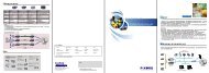
2. P500 Network CameraCOM/ GPIOLAN PortReset holeAudio Line OutUSB PortsPower JackCamera LensBuilt-In Microphone- 5 -
Chapter 3Installation1. Hardware connectionPhysical connection of P1500 video server1. Prepare a PC with Ethernet link to the network2. Connect P1500 device to a network hub/switch with standard pass through (CAT5) cable, orconnect directly to PC with a cross over cable.3. Connect the video output of a CCD camera using standard 75 Ω coaxial cable terminated withBNC connector.4. Connect power jack- 6 -
5. Ensure the power adapter specification matches the power system (110V or 220V). Connectthe adapter to the outlet.6. Check both LEDs (Power/Network); ensure they are light on after the steps above.Follow the same steps as connecting P1500 video server except step 3, to perform the P500connections.Physical connection of P500 Camera2. Software InstallationThe following software is necessary for the proper display and use of the P500/1500 from the Web site.- 7 -
The software will be taken from the Software Package CD.IP InstallerThe IP Installer is used to locate and configure network cameras and video servers on the LAN. Thisutility is useful for conveniently configuring the network settings of the device, or for finding a device oncethe network settings have been modified.To install the IP Installer, from the Software Package CD UI, select IP installer, then follow the on screeninstructions.Component InstallerThe ActiveX component is used by our devices for video display and device configuration. Usually, whenyou connect to the P500/1500 via IE browser, the ActiveX component will be installed automatically. If thecomponents can not be installed, install this software from the Software Package CD.XVID CodecAn MPEG-4 codec is applied for displaying the video stream and playing the recoded AVI files. If thevideo stream can’t be displayed or the recorded AVI files can be play on PC, install this software from theSoftware Package CD.VLCThough not necessary, this can be used for viewing the streaming without a Web browser.- 8 -
3. Network ConfigurationIP Installer is a utility that provides an easier, more efficient way to configure the IP address and networksettings of the devices. It even provides a convenient way to set the network settings for multiple devicessimultaneously using the batch setting function. Moreover, IP Installer can save the network settings forall devices as a backup and restore them when necessary.Preparation before IP Assignment1. Always consult your network administrator before assigning an IP address to your server in order to avoidusing a previously assigned IP address.2. Ensure the P500/1500 is powered on and correctly connected to the network.3. MAC Address: Each device has a unique Ethernet address (MAC address) shown on the label of thedevice as the serial number (S/N) with 12 digits (e.g. 000429-XXXXXX).*0004290000B14. Although the IP Installer is able to find and configure any P500/1500 on the LAN except those that arebehind a router, it is a good idea to set the host PC to the same subnet. In order to connect to theWeb-based user interface of P500/1500, the host PC must be in the same subnet. For more informationabout subnets, please consult your network administrator.Using IP Installer to Assign an IP Address to P500/15001. Once IP Installer has been successfully installed on the PC, double click the IP Installer icon on thedesktop, or select it from Start > Programs > IP Installer > IP Installer > Launch IP Installer.- 9 -
2. Click the menu bar Tool > Search Network Device to search the device in the LAN.3. From the list, select the device with the MAC Address that corresponds to the P500/1500 that is to beconfigured. The MAC Address is identical to the unit’s S/N (Serial Number).4. Double click the item to open the Property Page for the selected device or click the menu bar View >Property.- 10 -
5. After filling in the properties, click [Synchronize] button to complete the configuration settings in theremote P500/1500 while saving configuration in the PC. If click [OK] button, the configuration is only besaved in the PC.Open the Web-based UI of the Selected P500/15001. To access the Web-based UI of the selected unit, run the View > Open Web on the menu bar.2. If the device has been configured correctly, the default Web browser will open to the home page of theselected device.3. If you find your browser is opened and automatically connected to the P500/1500 Home Page, it meansyou’ve assigned an IP Address to the unit successfully. Now you can close the IP Installer and start to useyour P500/1500.- 11 -
Verify and Complete the Installation from Your BrowserWhen browsing the Home Page at the first time with the Microsoft Internet Explorer TM , you must temporarilylower your security settings to perform a one-time-only installation of the ActiveX component onto yourworkstation, as described below:1. From the Tools menu, select [Internet Options]2. Click the [Security] tab and then click [Custom Level] button to see your current security settings.3. Set the security level to Low and click [OK].4. Type the URL or IP address of your P500/1500 into the Address field.5. A dialog box will pop up asking if the ActiveX control should be installed. Click [Yes] to start theinstallation.6. Once the ActiveX installation is complete, return the security settings to their original value, as notedabove.- 12 -
Chapter 4Using the Web UIStart your Web browser and enter the URL or IP address in the Address field. The Home page of theP500/1500 is now displayed.The status of thevideo streamThe display of channel information can beconfigured in the OSD setting, includingvideo status, channel number, camera title,frame rate and transfer speed (bit rate).Note: Please notice to install the version of XVID codec and recommends V1.1 above, it can be found in theCD package.- 13 -
1. Live ViewFunctions in live view pageThe following are the available keys in the Live View mode:ButtonDescriptionSelect the display language for web user interfaceCheck “Actual Size” to display the video stream at the actual resolutionCheck “Audio” to enable audio recording.Click “Rotation” to rotate the selected video on 90 degrees clockwise direction.Click “Record” to start/stop recording.Click “PTZ” to show up a panel for the PTZ operation.- 14 -
Click “Deinterlace” to expend the option of deinterlace On/OffUsers need to set the file path before taking the snapshot. Click on [BMP] or [JPEG]to take an image with the bmp or jpeg file format respectively.Set the recording parameters including the recording path, file name, total filespace, maximum file length, enabling/disabling cycle recording and synchronize totimestamp. Click on “Setting” to apply the change.Go to the Playback page for search and play back recorded video fileNote: The user that log in with user account* can’t use the Playback functionGo to the Configuration page for setupNote: The user that log in with user account* won’t have an access to this page* P500/1500 user setting can be categorized in three groups, the Admin, operator and user. Detaildescription can be found in Configuration page > System > User.- 15 -
P/T/Z Control for Dome CameraThe following are the available keys to control the PTZ dome camera:ButtonDescriptionSelect the preset point for quick view or setupClick on the arrow buttons to move the camera to that directionClick on the rectangle button to stop the movementZoom out the videoZoomZoom in the videoStop the adjustmentOpen the iris and reduce glareIrisOpen the iris and brighten the pictureStop the adjustmentThe target will become fartherFocusAuto PanSaveThe target will become nearerStop the adjustmentActivate the auto pan functionStop the auto pan functionClick this button will save the current data as a preset point- 16 -
2. PlaybackTo play back the recorded file, click the button in Home pageButtonDescriptionThis will be displaying playback status include the speedof playing, playing mode and name of the controlling user.Select “Record HDD” or “Backup HDD” to search for therecorded file. Click [Search] button to open the Searchpanel, see Figure 1.Click this button to expand a setting panel for recordingthe playback stream to the client PC, see Figure 3.Click this button back to the Live View modeGo to the Configuration page for setupNote: only 1 user can control play back streaming in a meantime. Other than the first user will be able to seethe playing only (not to control) and who is controlling.For the first user (must at least have an operator authority) going to start playback:1. Select the hard disk that will be searched for.2. Click Search button to open the Date/Time panel for choosing.3. Select by Date/Time in the calendar. To know the usage of the calendar, just move the cursor on thebutton, the tips for the button will appear.4. After select the Date/Time, click on [Begin Playback] button to playback all recorded video from theselected time or [Event list] button to choose the recorded video files from events list, see figure 1& 2.For other clients (even logged in as an administrator)As one user is controlling the playback, the other clients must wait until the user stops the playback function.During the waiting time these clients can only view the streaming of playback.- 17 -
Close this panelThe start and end time of the all video recordingStatus of control playbackThe event type of the recording you can select to playThe start time of the recording you can manual inputor click calendar to playYou can click this to change play timeYou can click this to increase of number or press buttonof “Shift” and click this to decrease of numberYou can click button of “Begin Playback” to play time orclick “Event List” to play event listFigure 1Current page Total page “Next“” buttonEvent ListItemChannelEvent TypeDurationEvent TimeEvent DateFigure 2- 18 -
Playback ScreenController’s ViewOther clients’ View- 19 -
The following are the available keys to control the playback:ButtonDescriptionRotation: Rotate the playback images.Record: Record the playback video while viewing.Click “Deinterlace” to expend the option of deinterlace On/OffSame operation as in live page. Snapshot the playback video.Play / Pause / Resume the playbackBack to 1X speed for playbackStop the playback and exit the Playback functionFast forward / Rewind the playback. 1X ~ 32X speedsselectable.Playback in slow motion. After pause, select the speed from1X ~ 1/32X.Show the status of playback.Click [Search] button to search and play back the recorded video.See Remote Record Playback Stream for detail.Click this button back to the Live View modeGo to the Configuration page for setup- 20 -
Remote Record Playback StreamThe playback stream can also be saved to a client PC while viewing. This is a handy function for thatwhen a user is far away from P500/1500 but needs an actual copy of recorded video file.1. Set a path to store the video. Click on [Record setting] button. A setting panel will be expanded andshown. See below figure.2. Press on the red button [Record], the playback video will be saving to the path set previously.3. Besides save playback video, user can also snapshot an image from the video. The operation isidentical to operating in the live page.- 21 -
3. Configuration pageClick “Config” icon to open the Configure Page.- Video: Set up the resolution and quality for recording and live view, and the schedule recording- Camera: Setup video parameters, PTZ settings for cameras- Event: Setup for event trigger- System: Setup for system including date/time, user, COM port and commands etc.- Network: Setup for network- Storage: Setup for recording storage and schedule.- Home: Back to the Home PageThe detail descriptions / configurations are in the following chapter.- 22 -
Chapter 5Configure the Settings with Web UI1. Sub itemsVideo:Camera:Event:System:Network:Storage:- 23 -
2. Video Setup (Available for Administrator only)Video SetupVideo system: Configuration of video system in NTSC, PAL or Auto for auto detection of connectedcamera. This option only applies (presents) to video setup page of P1500 video server.Total IPS: Decide each “Total IPS” in Day, Night and Weekend of time for this channel, up to 30 for eachtime period. When stream2 is enabled, the total IPS can be shared by both streams.Stream 1 IPS: Set distributed IPS for Stream1 out of 30.Stream 2 IPS: Set IPS for Stream 2 out of a number the rest IPS after occupied by Stream 1.- 24 -
Stream 1:- Resolution: Streaming / Recording resolution can be selected from 352X240 (SIF), 720X240(Half D1) and 720X480 (Full D1).- GOP: Define a duration that a GOP (Group of Pictures) will present. Options start from 1/2 to 1,2, 3 and 4 FPS. The images will be from clearer to less clear accordingly, the required recordingspace will be relatively increasing in the choice of smaller number.- MPEG4 Profile: Selection of SP (Simple Profile) or ASP (Advanced Simple Profile).- Video Mode: Choose video encoding mode between VBR (Variable Bit Rate) and CBR(Constant Bit Rate)- Video Quality: When VBR mode is set, the video quality can be set from 31 levels (1~31, high~ low). Note: when resolution is set to Full D1, the quality level can only be set from 5 to 31.- Video Bitrate: When choosing CBR for the video mode, video bitrate can be selected among64 Kbps, 128 Kbps, 256 Kbps, 512 Kbps, 768 Kbps, 1 Mbps, 1.5 Mbps, 2 Mbps, 3 Mbps and 4Mbps.- Event action: Choose Motion (motion detection), Sensor (sensor triggering) or Both (enableboth types) for the event action. The configurations hereafter titled with “Event” will take effectswhen any event action is selected; no effects when None is selected.- Event max IPS: Select the maximum IPS that will be applied when there is an event.- Event Mode: Choose encoding mode (VBR/CBR) when there is an event.- Event Quality: Choose image quality when there is an event.- Event Bitrate: Select the video bitrate when there is an event. The CBR must be selected forevent mode to enable this selection.Stream 2:- Dual stream enable: Set the second stream On/Off.- Stream format: The stream format can be set to “MJPEG” or “MPEG4”.- MPEG4 Profile: Selection of SP (Simple Profile) or ASP (Advanced Simple Profile).- Resolution: Streaming resolution can be selected from 352X240 (SIF), 720X240 (Half D1) and720X480 (Full D1).- Video Mode: Choose VBR or CBR for stream2 video encoding mode.- Video Quality: When VBR mode is set the stream2 video quality can be set from 31 levels(1~31, high ~ low) in MPEG4 format or 100 levels (1~100, low ~ high) in MJPEG. Note: whenresolution is set to Full D1, the quality level can only be set from 5 to 31 in MPEG4 mode, orfrom 1 to 90 in MJPEG.- Video Bitrate: Choose Stream2 video bitrate when video mode is CBR.- Apply: Confirm the settings.- 25 -
3. Camera SetupGeneral Setup- Brightness / Contrast / Saturation / Hue: Adjust the values from -100 to +100.- BLC: Enable/disable BLC (Back Light Compensation) function.- AES: Enable/disable AES (Auto Electronic shutter) function.Note: The BLC and AES functions will not appear in this page when connecting to a video server,P1500 (showonly in camera P500 setting page)- Camera Title: Input the camera title to shown on the screen.- Stream time: on/off the time displaying on the live video.- Stream title: on/off the title displaying on the live video.- Stream text: when stream title is set off, this filed can be input some texts for displaying on the video.- Load Default: Restore to the default settings.- Apply: Confirm the settings.- 26 -
PTZ Setup- PTZ Setting:Remove: No dome camera is connected to this channel.Add: A dome camera is connected to this channel.- PTZ Protocol: Various protocols can be selected, including PELCO P, PELCO D, LI-LIN andDynacolor.- PTZ ID: The ID number must match the ID address set by the dome camera.- Speed: Select the control speed from 1 ~ 10.- Apply: Confirm the settings.- 27 -
OSD Setup- OSD Display: Check the check box to display the following messages on the video of each channel.Note: The settings work with this client PC only; it won’t affect/change the settings of this device.- Status Display: Display the video status (Live or Playback video).- Channel Display: Display the channel number.- Title Display: Display the camera title.- Frame rate Display: Display the frame rate and bit rate.- Apply: Confirm the settings.Status DisplayChannel DisplayFrame rate DisplayTitle Display- 28 -
4. Event SetupGeneral Setup- Event Icon: M / S displaying on the screen indicates respectively motion detection or GPIN istriggered. Set this function “On” to enable displaying the two icons.- Event Duration: Set the duration time for recording after the event goes away. Available selectionsare 5, 10, 15, 20, 25 and 30 seconds.- Pre Alarm: When an event is triggered, a video clip will be sent with Email or saved to FTP site. Youcan adjust this option to determine the beginning time of video clip before the event is triggered. Theunit is in second.- Apply: Confirm the settings.- 29 -
Triggers ConfigMotion trigger: Define parameters for actions responding to detected motion.- Motion Detect: Set the Motion Detect feature for each channel to “ON” or “OFF”.- Alarm Out: Enable a relay output that will respond to a detected motion.- Pass Alarm: Adjust this option to determine the end time of a video clip after the triggeredevent. The value is counted in second.- Email Notice: Enable or disable the Email notice when motion detection is triggered.- Email Attachment: Set whether attach the video clip with the Email notice when motiondetection is triggered.- FTP Storage: Enable or disable whether send the video clip to FTP site when motion detectionis triggered.- CGI Alert: Enable or disable to send CGI alert when motion detection is triggered.- Period Time / Week: Select the period that the motion detection should be activated. Day、night、 weekday、 weekend or all the time.- Sensitivity: Set the sensitivity of motion detection.- 30 -
GPIN trigger: Apply the sensor relays as trigger. Define the actions/parameters responding to an event- Alarm in: enable the GPINs as a sensor for the event triggering.- Alarm Out: Enable a relay output that will respond to a triggered sensor.- Normal state: set the relays’ initial status.- Pass alarm: as described in motion config.- Email notice: send email responding to a sensed event- Email attachment: send email with attached video file.- FTP storage: send video file to FTP server responding to a sensed event.- CGI alert: enable the CGI alert responding to a sensed event.- Period time / week: select the period of time/day in a week that the sensor will be activated.- 31 -
Video loss trigger: Set actions responding to an event which the video is missing. For instance, line hasbeen cut or camera has been crashed.- Video loss detect: on/off this function.- Email notice: as described in previous two items.- CGI alert: as described in previous two items.- 32 -
Motion Area SetupMove mouse cursor to point the area, left-click mouse to set the area for motion detection; left-click theselected area again will clear the area.- Select All: Clear all areas for motion detection.- Clear All: Select all areas for motion detection.- Set: Confirm the settings.- 33 -
GPIO Setup- GPIO Input Status: Displays the current GPIO input status- Relay Settings: Displays the output relays’ status. The relays can be forced open or closed.- 34 -
5. System SetupGeneral Setup- Unit Name: Assign a name for the device.- Model: The model name of the device.- Hardware Version: The version of the hardware.- Software Version: The version of the software.- Firmware Version: The version of the firmware.- Apply: Confirm the settings.35
Date/Time SetupSet the year, date and time for the device.- DST Enable: If your region use daylight saving time, set the item to “ON”.- Bias: Set the amount of time to move forward from the standard time for daylight saving time.- Start: Set the beginning date/time of the daylight saving.- End: Set the ending date/time of the daylight saving.- NTP Enable: Set to “ON” if you wish to connect to a NTP server, this will synchronize the time withthe time server via network.- GMT: Set the time zone.- NTP Server: Input the IP address of the NTP server.- Set <strong>Manual</strong>ly: Set the time manually. You can select the time from the calendar.- Apply: Confirm the settings.36
User Password Setup (Available for Administrator only)- Enable Authentication: Select “YES” to enable the password authentication.- User name / Password: Up to 15 accounts can be added for accessing this device. The accountname and password can be flexible (but restricted in 8 characters long of any combination of 0-9, a-zor A-Z).- Group: A user should also be configured into a group (Administrator, Operator, User) for differentlevel of authority, in addition, the rights on access to the device (the capabilities of viewing live video,controlling PTZ cameras or none/both of them) if it is not set to the administrator group.- Apply: Confirm the settings.37
COM Port Setup- COM Status: Set COM port for PTZ, RS-232 or RS-485.- PTZ ID: The number must match the ID address set by the dome camera.- Baud Rate: Set the value if necessary.- Data Bit: Set the value if necessary.- Stop Bit: Set the value if necessary.- Parity: Set the value if necessary.- Flow Control: Set the value if necessary.- PTZ Protocol / Status: Display the PTZ protocol and the status of the connected dome camera.- Apply: Confirm the settings.38
System Commands (Available for Administrator only)- Factory Default: Restore the settings to the factory defaults.- Reboot: Restart the device.39
System InformationDisplay the information of this device. Information includes video port, resolution video type, bit rate, PTZmodel/status, motion status, sensor status and ActiveX version.40
System AudioSystem audio enable and adjustment: Mute check box for silence, Volume for the sound volumeadjustment.41
6. Network SetupGeneral Setup- Ethernet Mode: If using static IP, set to “Static” and then setup the following settings. If there is a DHCPserver on the network, set to “DHCP”, the device will get the following settings from the serverautomatically.- IP Address: Set the IP address of the device.- Subnet Mask: Set the subnet mask.- Gateway: Set the IP address of the gateway on the network.- MAC Address: Shows the MAC address of the device.- HTTPS: on/off the HTTPS option.- HTTP Port: Change the port if necessary.- RTSP Port: Change the port if necessary. Default port is recommended.- RTSP Start: Change the port if necessary. Default port is recommended.- RTSP End: Change the port if necessary. Default port is recommended.- DNS1 / DNS2: Set the IP address of the DNS server.- Apply: Confirm the settings.42
DDNS SetupDynamic DNS Settings 1:- DDNS Enable: DDNS allows the dynamic IP address to be registered so others can connect to it by a domainname. If you wish to use DDNS service and set to “ON”.- Host Name: Assign a host name for the device, this name will be the domain name.- Port: Change the port if necessary.- DDNS Server: Input the domain name of the DDNS server.- Router Incoming Port: If the device is connected to a router, change the port to match the Port Forwarding settingin the router.- Update Time: Set the interval time to detect the IP address and update to the DDNS server. The time setting mustbe in the range 600~86400 seconds.- Response: After confirm the settings; a message will appear for check the DDNS status.- Apply: Confirm the settings.43
Dynamic DNS Settings 2:- DDNS Enable: As in settings 1 mentioned.- Host Name: As in settings 1 mentioned.- Account ID: For the server needs an account to log in, the field here is then for the account identification.- Password: password for the account to log in.- Update Time: As in settings 1 mentioned.- Response: As in settings 1 mentioned.- Apply: Confirm the settings.44
Email Setup- Email via SMTP: Set to “ON” if use a SMTP server to send the Email.- SMTP Server: SMTP server IP address.- SMTP Port: Change the port if necessary. Default is recommended.- Authorization: Set to “ON” if the Email service needs account and password.- SMTP Account / Password: If the SMTP server has enabled authentication function. You have to fill up theAccount and Password to pass through the authentication.- Email to Address: The Email address to receive the Email.- Email from Address: The Email address that send the Email.- Apply: Confirm the settings.45
FTP Setup- FTP enable: Set to “ON” if use a FTP server to receive the event notification.- Server IP: Enter the IP address of the FTP server.- User Name / Password: The account name and password to login the FTP server.- Storage Path: Path of the FTP site to put the file.- Apply: Confirm the settings.46
PPPoE Setup- PPPoE enable: Enable/disable PPPoE function.- User name / Password: Account authentication; enter user name and password for the PPPoEaccount.- Apply: Confirm the settings.47
7. Storage SetupStorage USB SetupDisplay the information and status of the storage devices that connected to P500/1500.- Active: represents the disk will act as a “Record” or “Backup”, or “Off” as taking no action.- Action: shows the disk’s mounting status, Add/Remove.- Priority: Set the priority in number if there is more than one disk. The number is counted from 0 to 8;0 indicates the top priority while 8 is the lowest. Disk with higher priority will always be taken to actunless it is full.- Type: the disk will be formatted with EXT file system if “Record” is taken active, while EXT or FAT filesystem can be applied for “Backup” activity- Format: Format the disk with these conditions.48
Storage Record Setup- Start Schedule Record: When set to “ON”, the recording will depend on the set day and night time,or weekend time.- Day Time Start: Set the beginning time of the day.- Night Time Start: Set the beginning time of the night.- Weekend Schedule: When set to “ON”, the weekend schedule will be enabled.- Weekend Start Week / Time: Set the beginning day and time of the weekend.- Weekend End Week / Time: Set the ending day and time of the weekend.- Overwrite Recording: When set to “ON”, if the record HDD is full, the recording will overwrite theearliest recorded file in the HDD.- Audio Recording: When set to “ON”, both video and audio will be recorded.- Apply: Confirm the settings.- “Record Hard Disk setting error!” This message shows when there is no storage to be set active.49
Appendix ASpecifications1. P500P-500SystemVideo CompressionEmbedded Linux, 32-Bit RISC Processor, 8MB Flash ROM, 64MB SDRAMMPEG-4 ASP / MJPEG, Dual streamingFull D1: NTSC = 720 x 480; PAL = 720 x 576Video ResolutionHalf D1: NTSC = 720 x 240; PAL = 720 x 288CIF: NTSC = 352 x 240; PAL = 352 x 288Frame RateImage DeviceLens TypeHorizontal ResolutionUp to 30(NTSC) / 25(PAL)1/3” Sony SuperHAD CCDCS mount, Fixed iris, Focal Length 6.0mm, F1.6; With DC-iris jack to support auto iris lensMore than 480 TV LinesMinimum Illumination 0.5 Lux at F2.0White BalanceBacklight CompensationAuto Electronic ShutterAutoON / OFF selectableON / OFF selectableEvent SystemLocal StorageNetwork InterfaceProtocolsAudio CapabilityPower SupplyTriggerActionGPIN, Motion detection,GPOUT, FTP, Email and alert messageSupport schedule / event recording via external USB2.0 port10/100 Base-T EthernetOptional IEEE 802.11b/g wireless LAN via USB (to be upgraded)TCP(UDP)/IP, HTTP, FTP, Telnet, SMTP, DHCP, NTP, DDNS, RTSP, RTP/TCP(UDP)1x Built-in Microphone, 1x 2.5mm Line out jack (to be firmware upgraded)DC switching power adapter, output: DC 12V/1.5AOptional built-in PoE IEEE 802.3afOperation TemperatureOperation HumidityDimension (L x W x H)Net Weight5 o C ~ 45 o C20% ~ 80% RHG135mm x 85mm x 40mm600 g (approximately)50
2 x USB 2.0 Host ports for external storage or USB wireless LAN (to be firmware upgraded)I/O Connectors1 x Mini-DIN for RS-485 / Photo-coupled GPIN / Relay GPOUT / Video out1 x Reset hole to restore factory defaults1 x RJ-45 Ethernet connector with 2 LEDs (power/status)Package Contents1 x DC In connector1 x CD (manual and software), 1 x Ethernet cable, 1 x Mini Din to Terminal block extend cable,1x Stand for mount, 1 x ACDC Power Adapter (Not included with PoE model)51
2. P1500P-1500SystemVideo CompressionEmbedded Linux, 32-Bit RISC Processor, 8MB Flash ROM, 64MB SDRAMMPEG-4 ASP / MJPEG, Dual streamingFull D1: NTSC = 720 x 480; PAL = 720 x 576Video ResolutionHalf D1: NTSC = 720 x 240; PAL = 720 x 288CIF: NTSC = 352 x 240; PAL = 352 x 288Frame RateAnalog Video Input / OutputPan / Tilt / Zoom ControlUp to 30(NTSC) / 25(PAL)2 x BNC (1 video input, 1 x video out)Yes, supports Peloco-P, Pelco-D, Lilin, Dynacolor protocolsEvent SystemLocal StorageNetwork InterfaceProtocolsAudio CapabilityPower SupplyTriggerActionGPIN, Motion detection,GPOUT, FTP, Email and alert messageSupport schedule / event recording via external USB2.0 port10/100 Base-T EthernetOptional IEEE 802.11b/g wireless LAN via USB (to be upgraded)TCP(UDP)/IP, HTTP, FTP, Telnet, SMTP, DHCP, NTP, DDNS, RTSP, RTP/TCP(UDP)1x 3.5mm Line in jack, 1x 3.5mm Line out jack (to be firmware upgraded)DC switching power adapter, output: DC 12V/1.5AOptional built-in PoE IEEE 802.3afOperation TemperatureOperation HumidityDimension (L x W x H)Net Weight5 o C ~ 45 o C20% ~ 80% RHG119mm x 142mm x 46mm510 g (approximately)2 x BNC connectors for analog video in / out2 x Line jacks (Audio In/Out)I/O Connectors2 x USB 2.0 Host ports for external storage or USB wireless LAN (to be firmware upgraded)1 x Mini-DIN for RS-485 / Photo-coupled GPIN / Relay GPOUT / Video out1 x Reset hole to restore factory defaultsPackage Contents1 x RJ-45 Ethernet connector with 2 LEDs (power/status)1 x CD (manual and software), 1 x Ethernet cable, 1 x Mini Din to Terminal block extend cable,1 x ACDC Power Adapter (Not included with PoE model)52
Appendix BThe Mini Din ConnectorThe mini-din connector provides control signal input and output, which including GPIO input, GPIO outputas Relay connection and one RS-485 port multiplex with COM port. It also provides connection of PTZdevice and external console to control the device.COM / GPIO MINI-DINPIN FUNCTION1 GPIN2 RXD (Receive Data)3 TXD (Transmit Data)4 RS-485A5 GND (System Ground)6 GPOUT- Relay NO7 GPOUT- Relay COM8 RS-485B9 Video OutGPIN: Input high when opening the connection; input low when sinking more than 10mA orshorting to pin 5 (GND).RXD (COM Port Receive Data)TXD (COM Port Transmit Data)RS485A/RS485B: To connect with external PTZ devices, please contact your dealer/distributorto get the information of the supported PTZ models.GND (System Ground): System Ground is also connected to chassis as frame ground.GPOUT-Relay NO/COM: When there is a triggered event, this can be a response that pin 6 isshort to pin 7 and enables an alarm device.Video Out: directly output the analog video signal.53
Mini-Din to Terminal block extended cableThis cable within the product package is provided for an easier application/connection. See below figure.54
Appendix CFAQ1. How can I set factory default?ANS:1. Unplug the power jack to turn off the power of P500/1500.2. Insert a pin into the reset hole as circled with red in the below figures. Sense a button and keepit pressed until instructed to release.3. Plug in the power jack to turn on P500/1500, in about 20 seconds the network LED circled inblue will be flashing4. Release the button (remove the pin from the reset hole).5. The P500/1500 should now be back to factory default. Have an access to the device bychanging to the attempt IP address from the default 192.168.0.200.P500P150055
Note:1. When P500/1500 can be scanned by IPInstaller with this IP “192.168.0.200” after factorysetting, it means the reset process is successful.2. There will be totally 9 On-Off flashings, within this period the reset progress will be launched. Ifthe inserted pin is removed before or after flashings, the system wouldn’t take any effect; thereset will be unsuccessful. Redo from step 1 for another chance.3. Do not remove power any time in the reset process, the flash memory inside the device can bedamaged otherwise.56
2. How to change the TV standard (P1500 only)ANS:1. Unplug the power jack to turn off P1500, and then set the DIP Switch in the front panel:- NTSC: set the switch 1 to the up position.- PAL: set the switch 1 to the down position.2. Plug in the power jack to turn on P1500, the video output of P1500 will meet the TV standard.57
3. How to upgrade firmware for the device?ANS:Download the newest software and unzip it into your local driver, for example "C:\temp". Then, confirmthe "flash.bin" (or flash_all.bin) file exists in this directory.Restart the device by clicking on the button on Configuration page -> System -> Commands.Caution: You must reboot the device before doing the following procedures; otherwise, someoccasional internal conflicts may endanger the Flash devices.Start the FTP session and log in to the P500/1500.For example, in our case for Windows XP:Enter DOS by " Start > All Programs > Command Prompt."Change to the directory where the latest flash.bin exists.Start ftp session by enter “ftp Enter "root" for USERNAME, "pass" for PASSWORD as default administrator; you will have to use youradministrator's USERNAME and PASSWORD to login if you ever added a user with administratorauthority.Set FTP to binary mode using the command "bin".In FTP session window, enter "bin"Upload the software into the device by FTP "put" command.In FTP session window, enter "put flash.bin"In FTP session window, enter "bye" to quit FTP session.FTP session may freeze for around 1~2 minute to transfer and automatically upgrade the software.Use “ping” to check whether the device is accessible. If you get replies after pinging, you then shouldbe able to access the device via Web interface. The figure of Command Prompt below shows anexample of the whole operation.58
Note: Flash products can become damaged if the updating operation is not performed correctly. So pleasefollow up above procedures carefully.59
4. Why ActiveX remains in old version after upgrading to new versionfirmware?ANS:Launch an IE browser and click on “Tools” -> “Internet Options”. The Internet Options window thenshows up.60
In Temporary Internet files, click on Delete Files.Press “OK” to confirm deletion.61
Re-open IE browser and access to the device. You will this time be prompt to install newer version ofActiveX control. After installation, you should see the new version installed.62