CSA-32e.pdf 1289KB May 02 2006 12:07:50 PM - DCC Supplies
CSA-32e.pdf 1289KB May 02 2006 12:07:50 PM - DCC Supplies
CSA-32e.pdf 1289KB May 02 2006 12:07:50 PM - DCC Supplies

You also want an ePaper? Increase the reach of your titles
YUMPU automatically turns print PDFs into web optimized ePapers that Google loves.
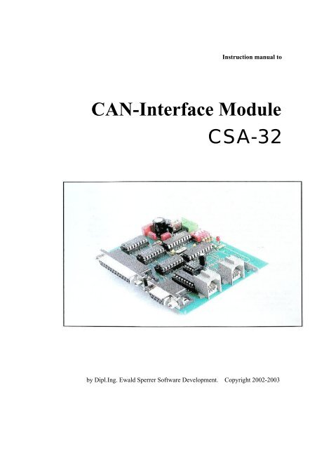
Instruction manual toCAN-Interface Module<strong>CSA</strong>-32by Dipl.Ing. Ewald Sperrer Software Development. Copyright 20<strong>02</strong>-2003
License AgreementNoteRevisionsAuthorSoftware that is part of this product as well as this documentation may bepassed to others only in its original condition. All rights (software anddocumentation) remains in any case with the author. The sale andcommercial use of this software and documentation without writtenpermission of the author is prohibited.The use of the software contained or supplied with this product (eitherstored or programmed in CPU’s) is only allowed in conjunction with theproduct itself.This manual as well as the hardware module <strong>CSA</strong>-32 was produced withgreat care. Should you have any comments, corrections or suggestions tothe manual or the module please forward them to the address below.Basic knowledge about electronic components and soldering skills are aprerequisite before attempting the assembly of this module. If needed,consult appropriate literature about this subject first.When operating this unit, please follow the relevant safety rules. Noguarrantee or restitution for damage or subsequent damage caused by thisproduct will be made. Any warranty will be void if this manual isn’tstrictly followed.We can’t guarrantee that this module works with every hardware andsoftware combination due to the number of possibilities. After inspectingthis product, you as end user or licencee respectivaly, will acept it “as is”.1. Edition V1.0, March 20032. Edition V1.1, June 2003Dipl.-Ing. Ewald SperrerSoftware developmentWeissenberg 23A-4053 HAIDAustriaBrand NamesCopyright“WINDOWS”, MS-WINDOWS and “MS-DOS” are brand names ofMicrosoft. All other product or company names are brand names orcopyright protected by the respective manufacturer.20<strong>02</strong>-2003 by E. Sperrer. All rights reserved. The copying of thisdocumentation or the products software for the commercial use withoutwritten permission of the author is prohibited.
Content1. General Notes...................................................................11.1 Safety precautions......................................................................................................11.2 Module description....................................................................................................21.3 Application.................................................................................................................32. Module Assembly.............................................................52.1 Parts list......................................................................................................................52.2 General assembly hints........................................................................................... ...72.3 Module assembly........................................................................................................82.4 Inspection...................................................................................................................113. Operation..........................................................................113.1 Module addresses.......................................................................................................113.2 Hook - up and wiring schematic................................................................................<strong>12</strong>3.3 Digital inputs and outputs..........................................................................................143.4 Initial power-up and testing with CANView.............................................................163.5 Inclusion in STP.........................................................................................................203.6 Problem solving..........................................................................................................214. Appendix...........................................................................224.1 Specifications.............................................................................................................224.2 Schematic...................................................................................................................234.3 Operating environment...............................................................................................234.4 Warranty.....................................................................................................................24
1. General Notes1.1 Safety notesFollow the safetyguidelines andregulationsapplicable in yourarea whenworking withelectricalappliancesPlease keep this instruction manual in a safe place for future reference.• Before you operate this module make sure it is intended for that purpose.• Install this module in an appropriate housing before operating it toprevent electrical shock .• Examine all attached wiring for breaks or insulation failure. Repair suchdefects immediately.• Before opening electrical equipment or working on them usingappropriate tools, ensure that the power cord is pulled first and any storedenergy is discharged.• When installing electronic components, choose them according to thespecifications given in the manual supplied with the equipment.• Contact a professional or the manufacturer if any explanation in thismanual is unclear.• Any error in assembling or operating this unit is your responsibility andno restitution of any damage will be made.• All semi conductors, especially IC’s, are susceptible to static discharge.Make sure your body is not electrically charged, by touching a metalbody first such as a copper water pipe.Wearing a ground strap or working on a ground mat is highlyrecommended.1
1.2 DescriptionThe <strong>CSA</strong>-32 module is a digital input/output device containing a CAN businterface. It is designed for the control of model railroads with a ZIMO<strong>DCC</strong> system using their CAN bus parameters (<strong>12</strong>5Kbit/sec transfer rate).Up to 64 bulbs orLED’s can beoperated by onePLV-32; thePTP-64 boardmanages up to 64push buttons.The module can be configured via CAN bus to act either as an input oroutput device with a bias voltage of +5V or 0V.The number of in/outputs can be raised to 192 by using the PLV-32 and/orPTP-64 boards; also available from us. The <strong>CSA</strong>-32 module contains thelogic for communication and control of these boards.Fig. 1. In/Outputs of CV-32 moduleA DIP switch is provided to assign an address between 1 and 15 to themodule. A maximum of 15 <strong>CSA</strong>-32 modules are allowed on one CAN bus.Power is supplied from either an external source (8-24V DC or AC) ordirect from the ZIMO CAN bus connector. The power required for othermodules, like the PLV-32 or PTP-64, can in both cases be supplied by the<strong>CSA</strong>-32 module.The module is controlled by a PIC16F627 micro controller, is included inthis kit and already programmed. An LED indicates whether the module isin the programming or operations mode and whether it is sending orreceiving data.2
1.3 ApplicationsThe main purpose of the <strong>CSA</strong>-32 module is the control of light bulbs orLED’s and as an input device for push buttons, as is commonly used inmodel railroading for signals and switch boards.Even though bulbs andLED’s can be connected directly to a <strong>CSA</strong>-32 module, one or severalPLV-32 or PTP-64 boards are usually used to increase the numbers ofconnections and thereby bringing the cost down. Each <strong>CSA</strong>-32 moduleaccepts up to six PLV-32 or three PTP-64 boards but not mixed at the same<strong>CSA</strong>-32 module! A total of 192 bulbs/LED’s or 192 push buttons may beconnected to each <strong>CSA</strong>-32 module.Furthermore, occupancy detectors may be connected provided the detectorscan indicate an occupied state permanently, using a +5V input signal (notmomentary switches). 24 detectors may be connected to each <strong>CSA</strong>-32module. A separate ground circuit is required between the detectors and the<strong>CSA</strong>-32 module.Please note thatSTP doesn’tsupport the directconnection of pushbuttons and bulbsto a <strong>CSA</strong>-32module, withoutthe use of PLV-32or PTP-64 boards.The STP software which beginning with version 4.3 supports the <strong>CSA</strong>-32modules for the above applications, controls the modules. Furtherinformation regarding the configuration of the STP software in conjunctionwith <strong>CSA</strong>-32 modules can be found in the STP manual (page 4-30).When powering a module up for the first time, a flashing LED indicatesthat it is not configured for a specific task yet. That is, whether themodule’s task is to check for occupancy, control lights or accept pushbutton inputs. The configuration is done in STP via CAN-bus and isconfirmed a success when the LED stops flashing and remains lit. Theconfiguration is permanently stored and the LED is on steady when the unitis powered up the next time. Even so, the configuration may be changed atany time.Please note that the control of this module by Zimo components only (MX1and MX2 w/o PC) is not possible at this time. The application of thismodule in other areas is conceivable but strictly at the users own risk! TheCAN-bus protocol is available at the request from the manufacturer.3
This page is left blank on purpose4
2. Module Assembly2.1 Parts ListQty Code Description Value Conrad # Reichelt #1 BR1 Bridge rectifier B80C1<strong>50</strong>0 <strong>50</strong>1441 B80C1<strong>50</strong>0Rund1 C1 Electrolytic condenser 470uF, 35V 472530 RAD 470/351 C2 Styroflex condenser 0.47uF, 100V 4581<strong>12</strong> MKS-4 470n2 C3, 4 Ceramic condenser 18pF 457159 KERKO 18p1 C5 Styroflex condenser 0.01uF, 63V 455334 MKS-2 10n1 D1 LED 3mm, red LED 184560 LED 3mm ST-rt1 D2 Diode IN4001 162213 IN 40011 ICI Voltage regulator 7805 179205 uA78051 IC2 CPU PIC16F627-04 1) 1)1 IC3 CAN-bus driver MCP2510-I/P 165113 2)4 IC4-7 I2C I/O interface PCF8574AP 2) PCF8574P1 IC8 CAN bus driver 82C2<strong>50</strong> 2) PCA 82C2<strong>50</strong>1 J1 2-pin socket K1X2 732416 STIFTL. 36G1 K1, 82-pin socket, 3.5mmpin configuration +suitable connectorsPTRX2729892 +729833AKL 182-<strong>02</strong> +AKL 169-<strong>02</strong>1 K3 SUB-D 25-pin socket D-SUB25 7413611 K4 SUB-D 9-pin socket D-SUB9 741345D_SUB BU 25USD_SUB BU 09US2 K6, 7 RJ<strong>12</strong> socket, 6-pin WESTERN-6P 2) MEBP 6-61 K9 Spade terminal 1X01 732745 FS-PW-6.351 Q1 Oscillator 4MHz 182087 4-HC49U-S5
Qty Code Description Value Conrad # Reichelt #5 R1-5 Resistor 10kO, ¼ W 403377 ¼ W 10K1 R6 Resistor 470O, ¼ W 403210 ¼ W 47<strong>02</strong> R7, 8 Resistor 10kO, ¼ W 403377 ¼ W 10K1 S1 Quad DIP-switch SCHIEB4 704776 NT042 -- 18-pin IC socket IC_SOCK18 189537 GS184 -- 16-pin IC socket IC_SOCK16 189529 GS161 -- 8-pin IC socket IC_SOCK8 1895<strong>02</strong> GS81 C6 Electrolytic condenser 10uF, 63V 3) 3)1 C7 Electrolytic condenser 10uF, 63V 3) 3)1 C11 Styroflex condenser 100nF, 63V 3) 3)3 C8-10 Electrolytic condenser 10uF, 63V 3) 3)1 IC9 Interface IC MAX232CP 3) 3)1 K5 9-pin socket D-SUB9 3) 3)1) Is included with this kit2) This part was not available from this supplier at time of printing3) This part is not needed for the module as described in this manual (Spring 2003)Addresses for above mentioned suppliers:Conrad ElectronicReichelt Elektronik e.KfrKlaus-Conrad-Strasse 1 Elektronikring 1D-92240 Hirschau D-26452 SandeTel. 09622/30-0 Tel. 04422/955-333Fax: 09622/408848 Fax: 04422/955-111www.conrad.dewww.reichelt.deConrad Electronic and Reichelt Elektronik are well known electronic parts suppliers in Europe.They can be found on the Internet. Parts are also available from other suppliers and arefrequently sold with the same part numbers or can be crossed over to the numbers used by them.6
2.2 General Assembly HintsBefore beginning with the assembly of this module, it is recommended tohave the following tools ready:• A heat resistant work base• A small side cutter• A small wire stripper• Tweezers to handle small parts• A soldering iron with a small tip• A soldering iron holder and a sponge• Solder, 0.5mm diameter• Wire with a minimum of 0.25mm diameterThe following are a few tips for the proper use of a soldering iron. Feel freeto skip this section if your soldering skills are sufficient:• Use a small soldering iron, maximum 30Watt. To ensure a speedy heattransfer to components, the soldering tip should be kept clean. Wipe thetip on a moist sponge every time before starting to solder.• Use exclusively solder designed for electronic work, such as: SN60PB(60% tin, 40% lead) containing flux.• Don’t use any other solder paste or liquid to solder electroniccomponents. They may contain acid, which will destroy components andcopper traces on circuit board.• Components can also be destroyed if the solder process takes too long.Other components may be de-soldered and copper traces lifted off thecircuit board if excess heat is applied.The solder time should be limited to 5 seconds especially when dealingwith semi conductors, LED’s, electrolytic condensers and IC’s, toprevent above problems.• Hold the solder tip to the work so that both parts to be joined aretouched. Add a little solder. Remove the solder wire as soon as it starts toflow. Hold the soldering iron for a few more seconds to allow the solderto flow evenly around the components legs and then remove the iron.• Don’t move the soldered components for about 5 seconds. A clean, shinysolder joint should be the result.• Cut the components legs just above the solder joint using a small sidecutter. Excess solder can be liquefied again, by applying heat with aclean solder tip. The solder will flow back to the tip of the soldering iron.7
2.3 Module AssemblyLocate all the components on the layout diagram before starting. Arrangethe components according to their type. The different component typeshave different peculiarities that need to be considered during installation.Resistors (R1 - R8)Resistors limit current flow. The resistor’s value is indicated with colorbands. Here a couple of examples:Value470ohm10kohmColor BandYellow-pink-brown (gold)Brown-black-orange (gold)The color shown in brackets is the allowed tolerance (5 or 10%). A resistorcan be installed in either direction.8
Condensers (C1 - C5)There are different kinds, the ordinary (ceramic, styroflex) and theelectrolytic condenser. The latter are polarity sensitive and can only beinstalled in a specific direction. The negative side is marked with a line andis also indicated in the schematic.Diodes / LED’s (D1, D2)Diodes are like one-way valves and are to be installed in a specificdirection also. One end of the diode is marked with a line which representsthe direction (exit side) current is allowed to travel. This line is also shownin the diagram.LED’s have two connecting legs of different lengths for polarity indication.The longer leg is the anode, which is shown in the diagram with twoarrows pointing up.IC’s (IC1 - IC7)The notch on an IC indicates the installation position. Again, this markingis also shown in the schematic. Sockets are soldered to boards to facilitatethe easy exchange of an IC. The voltage regulator (ICI) is to be installedwith the heat sink (metal bracket) pointing to the right, in direction of IC2.Rectifier (BR1)Rectifiers are used to convert AC power to DC. Check the schematic forthe proper installation position.Oscillator (Q1)The crystal generates a frequency of 4 MHz for the operation of the CANbus IC’s. No specific installation position.Switch (S1)A quad-DIP switch is used to set the address of the <strong>CSA</strong>-32 module. Itshould be installed so that the 4th rocker is closest to the board’s edge. Theswitches are closed (on) in the initial position.9
Sockets (K1, K3, K4, K6, K7, K8, K9, J1)The <strong>CSA</strong>-32 has a number of sockets at its disposal for power supply (K1,K8), CAN-bus (K6, K7) and in/outputs (K3, K4). They all make a secureand solder free connection possible. Depending on the CAN-bus sockettype (there are unfortunately several different styles on the market), thenose on the backside of the bottom CAN-bus socket (K6) may need to becut off with a side cutter. Otherwise there may not be enough room for theIC7. It may also be necessary to cut the two locator pins of both CAN-bussockets if their position differs from the holes in the board.The spade terminal (K9) is for the additional ground connection to theMX1 and should be used when occupancy detectors are employed (theholes may need to be enlarged a little). The CPU (central processing unit)may be reset by briefly connecting the two pins of connector J1 together.____________________________________________________________Important Note: The components C6, C7, C8, C9, C10, C11, IC9 and K5are not used with this version of the <strong>CSA</strong>-32 module and are not to beinstalled.____________________________________________________________AssemblyThe installation ofthe sockets mayneed some extrahelp when pushinghome the plasticpins of K6 and K7.There areunfortunately twodifferent styles ofsockets. You mayhave to cut thoseplastic pins off.The assembly in general starts with the smallest and ends with the tallestcomponent. Therefore start the assembly with the diode and the levelmounted resistors (R5-R8). The diode is also installed level with the board.Note the polarity marking on the diode.Solder the components from the other side of the board and cut-off theremaining legs as short as possible with a side cutter. After that, solder inthe IC socket, rectifier and oscillator, followed by the vertically mountedresistors (R1-R4).Continue with the condensers (smaller ones first, note polarity withelectrolytic’s) and the switch. At last, solder the voltage regulator (IC1,heat sink toward IC2), LED D1 (note polarity, long leg towards R6!) andthe sockets in place. Socket K8 (next to K1) should only be mounted if youactually plan to supply power to other modules, in order to prevent amix-up and subsequently connecting the power lead to the wrong socket.Now you are ready to insert the IC’s. Note the polarity markings and makesure you are not statically charged when doing this. Also, be very gentle soas not to bend any of the many IC legs.Please note: Electrolytic condensers, diodes, rectifiers and IC’s have to beinstalled according to their polarity! If they are installed with reversedpolarity, they could be damaged when powered up. In the worst case thewhole module may be damaged.10
2.4 InspectionDon’t power-up the module just now. There is a chance of injury due tofaulty or incorrectly installed parts.Remove the sharp edges that may have been left behind after cutting off thecomponents legs. Excess solder, pieces of wires or legs may still be stuckon the board. Check both sides of the board and remove such debris.Ensure that all components are installed and that the polarity is correct.Also make sure there are no bridges between component legs and coppertraces caused by excess use of solder. If there are, remove them as theycould destroy components. If everything checks out OK, continue withchapter 3.3. Operation3.1 Module addressesThe DIP switchhas to be installedon the board sothat switch #1 is onthe IC2 side andswitch #4 on theboards edgeBefore a module can be operated it has to have its own unique address (1 -15). This is what the DIP-switch is for (see Fig.2 on page 11).The switch settings for the different addresses are shown in the table below.Note that switch address 0 is reserved and can note be used as a moduleaddress.Address DIP Switch 2) Address DIP Switch 2)0 1) on-on-on-on 8 on-on-on-off1 off-on-on-on 9 off-on-on-off2 on-off-on-on 10 on-off-on-off3 off-off-on-on 11 off-off-on-off4 on-on-off-on <strong>12</strong> on-on-off-off5 off-on-off-on 13 off-on-off-off11
Address DIP Switch 2) Address DIP Switch 2)6 on-off-off-on 14 on-off-off-off7 off-off-off-on 15 off-off-off-off1) Address 0 may not be used.2) The DIP switch sequence is from left to right S1-S2-S3-S4.Address 7 for instance is set like this:Note: Address changes will only be read during power-up or during reset.Moving switches while the module is powered up will not change theaddress.3.2 Wiring schematic and module hook-upThe module requires 8 - 24V DC or AC to function properly. Power can besupplied by either the socket K1 or one of the CAN-bus sockets (K6, K7).The CAN-buscable also providessuitable power forthe module.____________________________________________________________Important Note: Under no circumstances is it allowed to use both, K1 andK6/K7, for power supply simultaneously; also socket K8 may not be usedfor power input!____________________________________________________________It is recommended to refrain from using the CAN-bus connector at theinitial hook-up and supply power to K1 exclusively.Socket K8 may be used to supply rectified power to other modules. This isstill unregulated power though, that is, it is taken before the 5V regulator(IC1) of the <strong>CSA</strong>-32 module. Because the voltage is relatively high (@40V), it is limited as power supply for other modules and adequate coolingof the voltage regulators is required!<strong>12</strong>
Details for wiringthe CAN-bus canbe found in theZimo and STPmanuals.As already mentioned, the CAN-bus is connected to sockets K6 and/or K7.It doesn’t matter which socket is used since they are internally wired inparallel.To increase the reliability of data transmission and to take the load of theground circuit in the CAN-bus cable, install a separate ground wirebetween the MX1 command station (connection marked as “Masse”) andthe K9 spade terminal.Connecting the 2 pins of the jumper J1 causes the <strong>CSA</strong>-32 to reset tofactory default values. This action is not needed under normalcircumstances. A reset can also be carried out by disconnecting the powerfor at least 5 seconds.13
3.3 Digital Inputs and OutputsOccupancy detectors, PLV-32 and PTP-64 modules are connected tosockets K3 and K4. These sockets are chosen as SUB-D because wires andconnectors are reasonable in price.SUB-D connectorsand sockets areused for the serialconnection to thePC.The <strong>CSA</strong>-32 module can be used in 5 different operating modes, which canbe activated via CAN-bus, e.g. using a PC with STP software. The 5 modesare:1. 32 digital input2. 32 digital output (this mode is not supported by STP)3. Controls up to six PLV-32 amplifier modules, for a total of 192bulbs/LED’s4. Controls up to six PTP-64 amplifier modules, for a total of 192 pushbuttons5. 32 digital input but invertet voltage levels (+5V = 0. 0V = 1)The 32 in and outputs are assigned to two sockets as follows:In/output 1 - 24: socket K3, pin #1 - 24Ground: socket K3, pin #25In/output 25 - 32: socket K4, pin #1 - 8Ground: socket K4, pin #9The pin numbers are printed on the sockets.Mode 1 and 5 may be used for occupancy detectors which indicateoccupancy according to the following logic:Mode 1: +5V = occupied, 0V = unoccupiedMode 5: +5V = unoccupied, 0V = occupiedPlease note that STP at the moment supports only 24 occupancy detectorsper <strong>CSA</strong>-32 module, connected to pins #1-24 of socket K3. Pin #25 isground and connected to each detector as well.14
Mode 2 is for testing purposes with custom software and small powerconsuming items like LED’s. Maximum output current is limited (seespecifications on page 22).Mode 3 and 4 increases the number of bulbs/LED’s or push buttons if usedtogether with booster modules PLV-32 or PTP-64. Please consult theappropriate manual regarding the wiring to the <strong>CSA</strong>-32 (these instructionsare equally valid for the older PSA-32 module ). Also note, that on a<strong>CSA</strong>-32 module either PLV-32 or PTP-64 modules may be connected butnot both.__________________________________________________________Important Note: The 64 diodes on the PTP-64 board have to be installedin opposite direction than is shown in the manual, if it is connected to aPSA-32 module.______________________________________________15
3.4 Power-up and testing with CANViewIt is recommended, that with the initial power-up no leads are connected tothe module other than the power leads to socket K1.Set the DIP switch to address #1 (off-on-on-on). Turn power on. The LED(D1) must be flickering fast. If it doesn’t, turn the power off immediately.The module may bealready set for anoperating mode ifthe module’s LEDis lit rather thanflashing . Programthe module toaddress 0, turn theunit off and backon and set the newaddress.The flashing diode indicates that the CPU started up correctly and is nowwaiting for a command on the CAN-bus as to which operating mode toengage (see section 3.3 in this manual).To test the CAN-bus communication, turn the power off and connect themodule with a CAN-bus cable directly to the CAN-bus interface at thecomputer. There should be no other modules connected to the CAN-bus forthis test.The picture below shows the pin-out of a PC CAN-bus connector. Connectonly CAN-L and CAN-H with the <strong>CSA</strong>-32 module!Power for this testhas to be suppliedby socket K1 only.Start the PCANView program. You’ll find the program on the STPV5 CDor on the floppy that came with the CAN-bus interface, if it isn’t alreadyinstalled on your PC. If you have an older CAN-bus interface, you can alsodownload a new driver from PEAK ( www.peak-system.com). Set the baudrate to <strong>12</strong>5 Kbit/sec.After the program started, turn the power to the <strong>CSA</strong>-32 module back on.The program window should look similar to the one below:16
In the Message column of the Receive pane, the address of the connectedmodule is shown (3E1, for module address 1). See table below.We will now send a command to set the module to operations mode 1 (for32 inputs).With the left mouse key, click anywhere on the Transmit pane and pushthe Insert key on the keyboard. A window opens up in which you enter thevalues 3D1 (ID), 1 (Length) and 01 (Data). The data value is the mode youwant to select:• 01 = mode 1 (32 inputs)• <strong>02</strong> = mode 2 (32 outputs)• 03 = mode 3 (PTP-64 control)• 04 = mode 4 (PLV-32 control)• 05 = mode 5 (32 inputs as in mode 1 but with inverted logic, that is logic1 is reported as 0 and vice a versa).Note that the ID (3D1) is for a module with address 1 (DIP switch setting).Use the table below to find the ID for other addresses:17
The “New Transit message” window looks as follows if module address 1is used:Setting the addressto 0 (all DIPswitches to on)resets the presentmode (to 0). Themodule has to bepowered off andon to take effect.Click on OK. A corresponding CAN command appears in the Transmitpane and can now be sent to the CAN-32 module by double clicking on thiscommand line.The LED D1 should now be lit steady, except for short flashes whilesending or receiving data. This indicates that the module accepted the moderequest. This mode is now permanently stored and the LED D1 will be litsteadily when powered up the next time.Moreover a new message is shown in the Receive pane:In operating mode5, theconfirmation datais 00 00 00 00 (allinputs inverted).In the data field the values FF FF FF FF are now shown which is theconfirmation signal from the module that all 32 pins are now set as inputs,mode1. All input pins are set to logic 1 (high) as long as they remain18
“open”, that is as long as nothing is connected to them.Now take a 10kohm resistor and connect one end to socket K9, which isground. Every time you connect the other end of the resistor to a pin on thesocket K3 or K4 (except for pins 25 on K3 or pin 9 on K4) the LED D1should turn off briefly and a new value should appear in the data field ofthe Transmit pane. Remove the resistor from the input pin again andFF FF FF FF should return.To see whether the module also operates the pins as outputs, select mode 2.Click again in the Transmit pane and hit the Insert key on the keyboard.Enter the values 3D1 (ID), 1 (Length) and <strong>02</strong> (data) and click on OK.Double click on the new line in the Transmit pane (for modules withdifferent addresses consult above table for proper ID). The module shouldconfirm this with 3E1 (ID), 1 (length) and <strong>02</strong> (Data). All outputs shouldnow be set to logic 0 (ground).You can now set each output to any bit setting by sending the followingcommand: 3D1 (ID), 4 (Length) and four values of your choice (from 00 toFF). For example: to set the outputs to “on” and “off” alternatively (Bitsettings 10 10 10......), send the following command: 3D1 (ID), 4 (Length),AA AA AA AA (Data). After the module’s LED flashed once the outputsat K3 and K4 should be configured as intended. Use a voltmeter to verifythe output voltages (a bit value of 1 sets the corresponding output to +5V. Avalue of 0, to 0V). In this example, output 1 (pin 1 of K3) should have 0V,output 2: +5V, output 3: 0V, output 4: +5V and so on.____________________________________________________________A CAN-bus command can be 8 bytes long. Each byte contains 8 bits.Rather than describing a byte as a chain of 8 zeros and ones, a system wasdeveloped that divides a byte in two groups of 4 bits. For each group anumber or letter is assigned according to its value. This is referred to ashexadecimal notation.Binary to hexadecimal conversion table:0000 = 0 0100 = 4 1000 = 8 1100 = C0001 = 1 0101 = 5 1001 = 9 1101 = D0010 = 2 0110 = 6 1010 = A 1110 = E0011 = 3 0111 = 7 1011 = B 1111 = FA group of 0000 is indicated with a 0 where 1111 = F. A byte such as10101010, separated in two groups 1010 and 1010 becomes AA inhexadecimal. Binary code 1111 1111 becomes FF.The (Length) 4 in our example indicates how many bytes are being sent(E.g. AA AA AA AA = 4 bytes at two groups each).____________________________________________________________19
3.5 Inclusion in STPSTP can use <strong>CSA</strong>-32 modules currently in four different ways:Setting the moduleto the moderequired is doneautomatically bySTP whenswitching to“Online” mode.• As interface for occupancy detectors (track section module)• To control signals (accessory module)• To control switch board indicator bulbs (switch board module)• As input device for switchboard push buttons (switch board module)For the last three operating modes (signal control, indicator bulbs and pushbutton inputs), the use of PLV-32 or PTP-64 modules respectively are aprerequisite, that is the bulbs/LED’s and push buttons are not connecteddirectly to the <strong>CSA</strong>-32 module. Please note that STP currently supportsonly 24 inputs for occupancy detectors, socket K4 cannot be used for thispurpose.____________________________________________________________Important Note: Every <strong>CSA</strong>-32 module connected to the same CAN-busrequires ist own unique address (DIP switch S1), even if not used with STP.<strong>CSA</strong>-32 modules including its address have to be entered in the STP“Parameter” window, according to the intended application (see above) aseither:<strong>CSA</strong>-24 as track section module, PLV-32/C as accessory module,<strong>CSA</strong>-32/T192 as switch board module using PTP-64 or <strong>CSA</strong>-32/L192 asswitchboard module using PLV-32. Only one entry for each <strong>CSA</strong>-32module is allowed.The numbering of track sections, when used as occupancy detectorinterface, is shown at the bottom of the track section modules parameterwindow (e.g. “This module uses sections 17-40”). The individual sectionnumber is given by the connecting pin of the <strong>CSA</strong>-32 module (the detectorconnected to pin one would be STP section #17, pin 2 would be #18 etc., inthe example above).More informationregardingaddresses can befound in the STPmanual.The address to be entered in STP for signals, switch board lights or pushbuttons comprises the <strong>CSA</strong>-32 address followed by a dot and by theconnecting pin number of the bulbs/push buttons (1 -192). For example: Alight bulb connected to output <strong>12</strong> of the second PLV-32, that is connectedto a <strong>CSA</strong>-32 module with address #3 is entered as 3.44 (3 is the <strong>CSA</strong>-32address, 44 is the <strong>12</strong>th pin of the second PLV-32 module, since thismodule’s pin numbers range from 33 to 64.For push buttons, an alternative method to writing the address is simply tooperate the button and the address will be automatically read by STP andregistered in the address field (needless to say that the affected <strong>CSA</strong>-32module has to be powered up).20
3.6 Trouble shootingHere are a few hints in closing in on problem areas, should the module notfunction as expected.If after powering up the module the LED doesn’t light up, remove thepower immediately and check the following:• Are all IC’s inserted all the way?• Is the installed position of IC’s correct (esp. IC1 & IC2)?• Is rectifier (BR1) and condenser (C1) installed with correct polarity?• Is the input voltage in the allowed range?• Is the LED (D1) installed with correct polarity?FAQ (Frequently asked question):Q: A component gets hot and smokesA: This or another component is installed in inverted position. Removepower immediately and check/replace component(s).Q: The LED is not flashing when powered up for the first time but rather litconstantly.A: Presumably, the module is already set to a specific operating mode. Setthe module address to 0 (all switches of the DIP switch S1 to “on”), turn thepower on (the LED should now be flashing) and off again. The operatingmode is now reset to 0. Set your original address again.Q: Some in/outputs can not be changed, they are stuck as either logic 1 or0.A: It is possible that one of the driver IC’s (PCF8574) is defective. TheIC’s are assigned to the following output pins: IC4 = K3 pin 1 - 8, IC5 = K3pin 9 - 16, IC6 = K3 pin 17 - 24, IC7 = K4 pin 1 - 8. Swap two of the IC’sto see whether the problem follows one of them.Q: The LED of the module flickers when turned on but no informationappears in the PCANView Receive window.A: Check the CAN-bus cable to the PC. Connect the MX1 in place of the<strong>CSA</strong>-32 to the CAN-bus and see if any information appears on the screen.If no, the problem is in the configuration of the CAN-bus interface or theCAN-bus cable. Also, check that the data transmission rate of PCANViewis set to <strong>12</strong>5Kbit/sec.21
Q: Even though the module starts up as it should, it doesn’t react to anycommands issued.A: With PCANView, find out which ID the module sends on the CAN-busduring start-up. The last digit or letter is the address (1 - F), which has to bepart of the ID when sending a command as well.4. Appendix4.1 SpecificationsDimensions:80 x 100mm (sockets may project past the edge ofthe board)Input voltage: 8 - 24V DC or AC; can also be supplied byCAN-bus connectorCurrent consumption: 25 mAMax. Output current: LOW: 25 mAHIGH: 300 mAAmbient temperature: 0 - 60 CMax. Humidity: 85%22
4.2 SchematicThe exact component description can be found in the parts list on page 5.The components IC9, K5, C6, C7, C8, C9, C10 and C11 are not used withthis module version.4.3 Operating environmentThe following conditions apply for a trouble free operation of the <strong>CSA</strong>-32module:• Not to be used outside or in damp rooms• The contact with water or other liquids must be prevented• The unit may not be turned on should there be combustible gases in thearea.• Should the module have come in contact with water (e.g. condensation),get it inspected first by a qualified expert.• The specified voltage ranges on the supply as well as the input/outputside have to strictly adhered to.• The ambient temperature may not be outside the range of 0 to +40C• The module is to be protected against heat and cold23
• The module is to be operated only with a qualified adult present.• Only original parts are to be used for repairs• The power to the module is to be turned off when not in use.Please note that the warranty is lost if above conditions are not met.4.4 WarrantyA 2-year warranty applies to this product. The warranty covers the freerepair or replacement of components supplied, provided the failure is adirect result of poor material or workmanship. Our liability is limited to thismodule and we will not be responsible for any subsequent damage to othercomponents that this unit is wired to, since we have no control of theassembly and connection of this module.We reserve the right to eitherrepair, upgrade, replace the unit or reimburse the purchase price.The warranty expires if:• an unfit soldering iron; solder, solder past or flux is used containing acid.• the assembly and soldering work is the cause of the products failure• the installation manual and the schematic is not followed• changes and repairs are attempted to this kit or a component• unauthorized alterations to the component layout and wiring is attempted• the boards current traces are destroyed or damaged• parts installed with wrong polarity• damaged by overloading the module• connected to wrong power source• damaged by unauthorized personnel• misused• damaged by electro static discharge24