Phase 4 â Wire L.T. Solid State ( Static) Whole Current ... - WBSEDCL
Phase 4 â Wire L.T. Solid State ( Static) Whole Current ... - WBSEDCL
Phase 4 â Wire L.T. Solid State ( Static) Whole Current ... - WBSEDCL
- No tags were found...

You also want an ePaper? Increase the reach of your titles
YUMPU automatically turns print PDFs into web optimized ePapers that Google loves.
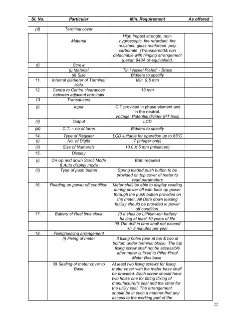
Sl. No. Particular Min. Requirement As offered(d)Terminal coverMaterial(f)Screw(i) Material(ii) Size11. Internal diameter of TerminalHole12. Centre to Centre clearancesbetween adjacent terminals13 TransducersHigh Impact strength, nonhygroscopic,fire retardant, fireresistant, glass reinforced polycarbonate (Transparent)& nondetachable with hinging arrangement(Lexan 943A or equivalent).Tin / Nickel Plated - BrassBidders to specifyMin. 9.5 mm13 mm(i) Input C.T provided in phase element andin the neutral.Voltage: Potential divider (PT less)(ii) Output LCD(iii) C.T. – no of turns Bidders to specify14. Type of Register LCD suitable for operation up to 65 o C(i) No. of Digits 7 (integer only)(ii) Size of Numerals 10.0 X 5 mm (minimum)15. Display(i) On Up and down Scroll ModeBoth required& Auto display mode(ii) Type of push button Spring loaded push button to beprovided on top cover of meter toread parameters16. Reading on power off condition Meter shall be able to display readingduring power off with back up powerthrough the push button provided onthe meter. All Data down loadingfacility should be provided in poweroff condition.17. Battery of Real time clock (i) It shall be Lithium-ion batteryhaving at least 10 years of life(ii) The drift in time shall not exceed+/- 3 minutes per year18. Fixing/sealing arrangement(i) Fixing of meter(ii) Sealing of meter cover toBase3 fixing holes (one at top & two atbottom under terminal block). The topfixing screw shall not be accessibleafter meter is fixed to Pilfer ProofMeter Box base.At least two fixing screws for fixingmeter cover with the meter base shallbe provided. Each screw should havetwo holes one for fitting /fixing ofmanufacturer’s seal and the other forthe utility seal. The arrangementshould be in such a manner that anyaccess to the working part of the22