Phase 4 â Wire L.T. Solid State ( Static) Whole Current ... - WBSEDCL
Phase 4 â Wire L.T. Solid State ( Static) Whole Current ... - WBSEDCL
Phase 4 â Wire L.T. Solid State ( Static) Whole Current ... - WBSEDCL
- No tags were found...
Create successful ePaper yourself
Turn your PDF publications into a flip-book with our unique Google optimized e-Paper software.
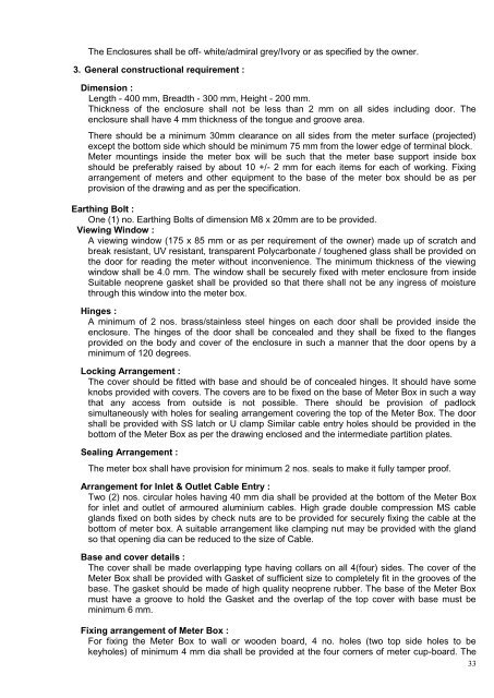
The Enclosures shall be off- white/admiral grey/Ivory or as specified by the owner.3. General constructional requirement :Dimension :Length - 400 mm, Breadth - 300 mm, Height - 200 mm.Thickness of the enclosure shall not be less than 2 mm on all sides including door. Theenclosure shall have 4 mm thickness of the tongue and groove area.There should be a minimum 30mm clearance on all sides from the meter surface (projected)except the bottom side which should be minimum 75 mm from the lower edge of terminal block.Meter mountings inside the meter box will be such that the meter base support inside boxshould be preferably raised by about 10 +/- 2 mm for each items for each of working. Fixingarrangement of meters and other equipment to the base of the meter box should be as perprovision of the drawing and as per the specification.Earthing Bolt :One (1) no. Earthing Bolts of dimension M8 x 20mm are to be provided.Viewing Window :A viewing window (175 x 85 mm or as per requirement of the owner) made up of scratch andbreak resistant, UV resistant, transparent Polycarbonate / toughened glass shall be provided onthe door for reading the meter without inconvenience. The minimum thickness of the viewingwindow shall be 4.0 mm. The window shall be securely fixed with meter enclosure from insideSuitable neoprene gasket shall be provided so that there shall not be any ingress of moisturethrough this window into the meter box.Hinges :A minimum of 2 nos. brass/stainless steel hinges on each door shall be provided inside theenclosure. The hinges of the door shall be concealed and they shall be fixed to the flangesprovided on the body and cover of the enclosure in such a manner that the door opens by aminimum of 120 degrees.Locking Arrangement :The cover should be fitted with base and should be of concealed hinges. It should have someknobs provided with covers. The covers are to be fixed on the base of Meter Box in such a waythat any access from outside is not possible. There should be provision of padlocksimultaneously with holes for sealing arrangement covering the top of the Meter Box. The doorshall be provided with SS latch or U clamp Similar cable entry holes should be provided in thebottom of the Meter Box as per the drawing enclosed and the intermediate partition plates.Sealing Arrangement :The meter box shall have provision for minimum 2 nos. seals to make it fully tamper proof.Arrangement for Inlet & Outlet Cable Entry :Two (2) nos. circular holes having 40 mm dia shall be provided at the bottom of the Meter Boxfor inlet and outlet of armoured aluminium cables. High grade double compression MS cableglands fixed on both sides by check nuts are to be provided for securely fixing the cable at thebottom of meter box. A suitable arrangement like clamping nut may be provided with the glandso that opening dia can be reduced to the size of Cable.Base and cover details :The cover shall be made overlapping type having collars on all 4(four) sides. The cover of theMeter Box shall be provided with Gasket of sufficient size to completely fit in the grooves of thebase. The gasket should be made of high quality neoprene rubber. The base of the Meter Boxmust have a groove to hold the Gasket and the overlap of the top cover with base must beminimum 6 mm.Fixing arrangement of Meter Box :For fixing the Meter Box to wall or wooden board, 4 no. holes (two top side holes to bekeyholes) of minimum 4 mm dia shall be provided at the four corners of meter cup-board. The33


