Radio Science Bulletin 313 - June 2005 - URSI
Radio Science Bulletin 313 - June 2005 - URSI
Radio Science Bulletin 313 - June 2005 - URSI
- No tags were found...

You also want an ePaper? Increase the reach of your titles
YUMPU automatically turns print PDFs into web optimized ePapers that Google loves.
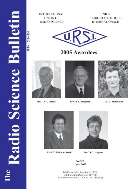
<strong>Radio</strong> <strong>Science</strong> <strong>Bulletin</strong>ISSN 1024-4530INTERNATIONALUNION OFRADIO SCIENCE<strong>2005</strong> AwardeesNo <strong>313</strong><strong>June</strong> <strong>2005</strong>UNIONRADIO-SCIENTIFIQUEINTERNATIONALEProf. I.V.I. Lindell Prof. J.B. Andersen Dr. D. MassonnetProf. Y. Rahmat-SamiiProf. S.C. HagnessThePublié avec l’aide financière de l’ICSU<strong>URSI</strong>, c/o Ghent University (INTEC)St.-Pietersnieuwstraat 41, B-9000 Gent (Belgium)
ContentsEditorial .......................................................................................................................3<strong>URSI</strong> Accounts 2004 ................................................................................................... 5<strong>URSI</strong> AWARDS <strong>2005</strong> .................................................................................................. 9Guest Editors’ Remarks ........................................................................................... 11Definition and Classification of Ultra-Wideband Signals and Devices................ 12Quantitative Comparison Between Matrix Pencil Method and State-Space-Based Methods for Radar Object Identification ............................................... 27An Ultra-Compact Impulse-Radiating Antenna.................................................... 39Triennial Reports Commissions .............................................................................. 49XXVIIIth General Assembly ................................................................................... 732004 Electromagnetics Prize Awarded.................................................................... 75Conferences ............................................................................................................... 76News from the <strong>URSI</strong> Community ........................................................................... 87List of <strong>URSI</strong> Officials ............................................................................................... 90Information for authors ......................................................................................... 115Front cover: At the XXVIIIth <strong>URSI</strong> General Assembly in New Delhi (India), the scientists whose pictures feature on the frontcover were presented with the <strong>URSI</strong> Awards. Fore more information, please turn to page 9 of this bulletin.EDITOR-IN-CHIEFEDITORIAL ADVISORY BOARDEDITOR<strong>URSI</strong> Secretary GeneralFrançois LefeuvreW. Ross StonePaul Lagasse(<strong>URSI</strong> President)840 Armada TerraceDept. of Information TechnologyW. Ross StoneSan Diego, CA92106Ghent UniversityUSASt. Pietersnieuwstraat 41 PRODUCTION EDITORSTel: +1 (619) 222-1915B-9000 Gent Inge HeleuFax: +1 (619) 222-1606BelgiumInge LievensE-mail: r.stone@ieee.orgTel.: (32) 9-264 33 20SENIOR ASSOCIATE EDITORFax : (32) 9-264 42 88J. VolakisE-mail: ursi@intec.ugent.beP. Wilkinson (RRS)ASSOCIATE EDITORSP. Banerjee (Com. A)M. Chandra (Com. F)C. Christopoulos (Com. E)G. D’Inzeo (Com. K)I. Glover (Com. F)F.X. Kaertner (Com. D)K.L. Langenberg (Com. B)R.P. Norris (Com. J)T. Ohira (Com. C)Y. Omura (Com. H)M.T. Rietveld (Com. G)S. Tedjini (Com. D)For information, please contact :The <strong>URSI</strong> Secretariatc/o Ghent University (INTEC)Sint-Pietersnieuwstraat 41, B-9000 Gent, BelgiumTel.: (32) 9-264 33 20, Fax: (32) 9-264 42 88E-mail: info@ursi.orghttp://www.ursi.orgThe International Union of <strong>Radio</strong> <strong>Science</strong> (<strong>URSI</strong>) is a foundation Union (1919) of the International Council of Scientific Unions as direct and immediatesuccessor of the Commission Internationale de Télégraphie Sans Fil which dates from 1913.Unless marked otherwise, all material in this issue is under copyright © 2004 by <strong>Radio</strong> <strong>Science</strong> Press, Belgium, acting as agent and trustee for theInternational Union of <strong>Radio</strong> <strong>Science</strong> (<strong>URSI</strong>). All rights reserved. <strong>Radio</strong> science researchers and instructors are permitted to copy, for non-commercialuse without fee and with credit to the source, material covered by such (<strong>URSI</strong>) copyright. Permission to use author-copyrighted material must be obtainedfrom the authors concerned.The articles published in the <strong>Radio</strong> <strong>Science</strong> <strong>Bulletin</strong> reflect the authors’ opinions and are published as presented. Their inclusion in this publication doesnot necessarily constitute endorsement by the publisher.Neither <strong>URSI</strong>, nor <strong>Radio</strong> <strong>Science</strong> Press, nor its contributors accept liability for errors or consequential damages.2The<strong>Radio</strong> <strong>Science</strong> <strong>Bulletin</strong> No <strong>313</strong> (<strong>June</strong>, <strong>2005</strong>)
Editorial<strong>June</strong> in December?Yes, this is the <strong>June</strong> issue of the <strong>Radio</strong><strong>Science</strong> <strong>Bulletin</strong>, and it’s coming to you inDecember. This issue and the September andDecember issues of the <strong>Bulletin</strong> will be late, I’mafraid, and the responsibility is mine. I’m sorry.As one way of getting the <strong>Bulletin</strong> back onschedule, for the next few issues I will not bedoing the same level of editing on the materialwe publish as I have been.We have included in this issue material from the NewDelhi General Assembly, and all of the normal end-of-theyear listings of <strong>URSI</strong> radio scientists’ contact information,which would usually go into the December issue. Hopefully,we’ll be back on schedule by the spring.The XXVIIIth <strong>URSI</strong> GeneralAssemblyThe XXVIIIth General Assembly of <strong>URSI</strong> in NewDelhi, India, was a wonderful success. We had more than1400 attendees, and the quality of the technical sessions andposter presentations was outstanding. Equally outstandingwas the hospitality shown to all in attendance by our Indianhosts. As just one example, the banquet transformed thelawn and grounds of the National Physical Laboratory intoa wonderland of lights; food booths, with something forevery taste; wandering performers; handicraft booths; stageshows with puppets, live actors, acrobats, and dancers; anda pair of elephants giving rides at the entrance! Theinvolvement of the President of India in the openingceremony, presenting one of the General Lectures, andhosting a most elegant tea for the Young Scientists made thewhole experience of the General Assembly even morespecial. Heartfelt thanks go to Dr. A. P. Mitra, Dr. V.Kumar, Dr. P. Banerjee, Dr. M. K. Goel, and all of theircolleagues on the Local and National OrganizingCommittees, as well as their many colleagues at the NationalPhysical Laboratory, for the years of effort that made all ofthis possible. Special thanks, too, go to Prof. Gert Brussaard,the Coordinator for the Scientific Program, who led theorganization of the scientific program, and whose ability toadapt the organization to the changing needs of the GeneralAssembly as it was happening made the whole experienceso very excellent.The Council voted to hold the XXIXth <strong>URSI</strong> GeneralAssembly in Chicago, Illinois, August 9-16, 2008. Prof.George Uslenghi, incoming Chair of the US NationalCommittee for <strong>URSI</strong>, is the Chair of the OrganizingCommittee, and will be the AssociateCoordinator for the Scientific Program. Dr.M. K. Goel, of India, will be the Coordinatorfor the Scientific Program.Special Section HonoringCarl E. BaumThis issue and the March issue of the<strong>Radio</strong> <strong>Science</strong> <strong>Bulletin</strong> contain special sectionshonoring Carl E. Baum on his 65th birthday.We have two guest Editors for these special sections, JürgenNitsch and Frank Sabath, and they have provided an excellentintroduction to the special section, this time focusing onsome of the more personal aspects of Carl Baum and hiscontributions outside of science and engineering.What is “ultra-wideband?” This is the basic questionone of our Guest Editors, Frank Sabath, and his coauthors,E. L. Mokole, and S. N. Samaddar, address in their paper.Ultra-wideband signals and systems have come into widespreadusage in recent years. However, what constitutes an“ultra-wideband” signal or system varies from applicationto application, field to field, and even among emergingstandards. The authors identify and explain the majordefinitions and usage of the term, and also explain thedifferences among these. They then suggest some furtherresearch and discussion that could lead to a commondefinition and a classification scheme that could be widelyapplicable.Model-based parameter estimation is the process offitting a model to a set of data, and determining the parametersof the model that best fit the data. A very simple example isthe fitting of a polynomial curve to a two-dimensional plotof some data. The parameters involved are the coefficientsof the polynomial. In the case of trying to identify scatteringobjects from radar data, it can be very useful to fit a modelbased on a sum of complex exponentials. There are severalmethods of doing this, and a comparison of three of thesemethods is the topic of the paper by Seongman Jang,Wonsuk Choi, Tapan Sarkar, and Eric Mokole. Theyconsider the Matrix Pencil Method and two methods ofretrieving harmonics using a state-space approach. Theycompare the ability of these three methods to accuratelydetermine the poles of the models for five canonicalelectromagnetic scatterers. While the three methods performsimilarly when the data are smooth, they produce differentresults when the data are not smooth, and when there issignificant noise present. There are also significantdifferences in the computational requirements for the threemethods.The<strong>Radio</strong> <strong>Science</strong> <strong>Bulletin</strong> No <strong>313</strong> (<strong>June</strong>, <strong>2005</strong>) 3
Leland Bowen, Everett Farr, Dean Lawry, and ScottTyo describe the design of a very compact impulse-radiating(ultra-wideband) antenna in their paper. The design isspecifically intended for use on a low-Earth-orbit satellite.One of the interesting aspects of this paper is that it tracesthe development of the ultimate design for the antennathrough three evolutions, with measured data and experiencewith the mechanical-design aspects being presented foreach. The antenna uses a collapsible design, with a metalliccoveredfabric forming the surface of the reflector. Thedescriptions of the development of the mechanism fordeploying the antenna, as well as for supporting the reflectorsurface, provide interesting insight into what is necessaryfor space-based applications. The final resulting antennaachieved many of the design goals, and is capable ofsupporting either single- or dual-polarization operation.Our Reviews of <strong>Radio</strong> <strong>Science</strong> papers will resumewith the next issue of the <strong>Bulletin</strong>.Best Wishes for the New Year!This will reach our readers in December, or shortlyafter the new year. At the end of one year and the beginningof the next, there are many opportunities to reflect on whatwe have received in the year past. I’m thankful for the honorand fun of being able to work with all of the wonderfulpeople associated with <strong>URSI</strong>, and particularly, with the<strong>Bulletin</strong>: Paul Lagasse, Inge Lievens, Inge Heleu, JohnVolakis, Phil Wilkinson, our Associate Editors, and the<strong>URSI</strong> Board (this time, both new and old). These people doa wonderful job, are very tolerant of an Editor’sshortcomings, and are very professional. Thank you!I wish all in the radio science community a mosthappy, healthy, safe, and prosperous New Year!Subscribe now !If you were not able to attend the <strong>URSI</strong> General Assembly inNew Delhi (India) last October, please fill in the form on theback cover of this issue and pay your <strong>Radio</strong>scientist fee as soonas possible with VISA or MASTERCARD, so that you willreceive the <strong>Radio</strong> <strong>Science</strong> <strong>Bulletin</strong> in the next triennium also.Please note that we do not accept cheques.4The<strong>Radio</strong> <strong>Science</strong> <strong>Bulletin</strong> No <strong>313</strong> (<strong>June</strong>, <strong>2005</strong>)
<strong>URSI</strong> Accounts 2004In 2004, a year preceding a General Assembly, the<strong>URSI</strong> balance already reflects some costs related to theGeneral Assembly, such as the meeting of the CoordinatingCommittee. We also observe increased expenditures due toincreased activities of the Commissions. The totalexpenditures were about 74 kEuros higher than in 2003. Atthe same time, the income was small, about 167 kEuros lessthan in 2003, mainly because in 2004 the member committeespaid only 79% of their dues. This resulted in a deficit ofabout 63 kEuros. The Treasurer suggests to act upon Article9 of the <strong>URSI</strong> Status and consider those member committeeswhich do not pay their dues for more than 2 years as havingresigned from the <strong>URSI</strong> and give them a possibility to applyfor the Associate Membership of the Union.In spite of the fact that the <strong>URSI</strong> assets shrunkcompared to the previous year, partly due to the turmoil atthe stock market and unfavourable US dollar-Euro exchangerate, the market value of our investments has increased byabout 14 kEuros.Nevertheless the <strong>URSI</strong> finances are sound and we arewell prepared for GA <strong>2005</strong> in New Delhi.Andrzej W. WernikTreasurerBALANCE SHEET: 31 DECEMBER 2004ASSETS EURO EURODollarsMerrill Lynch WCMA 3,169.09Fortis 4,162.71Smith Barney Shearson 67.78_________7,399.58EurosBanque Degroof617.02Fortis 128,185.32_________128,802.34InvestmentsDemeter Sicav Shares 17,187.24Rorento Units 84,425.18Aqua Sicav 48,333.83Merrill-Lynch Low Duration (305 units) 2,350.66Massachusetts Investor Fund 209,219.10_________361,516.01684 Rorento units on behalf of van der Pol Fund 9,407.03_________370,923.04Short Term Deposito 50,832.14Petty Cash 366.75__________Total Assets 558,323.85Less CreditorsIUCAF 9,865.71ISES 9,889.28_________(19,754.99)Balthasar van der Pol Medal Fund (9,407.03)__________NET TOTAL OF <strong>URSI</strong> ASSETS 529,161.83The<strong>Radio</strong> <strong>Science</strong> <strong>Bulletin</strong> No <strong>313</strong> (<strong>June</strong>, <strong>2005</strong>) 5
The net <strong>URSI</strong> Assets are represented by: EURO EUROClosure of SecretariatProvision for Closure of Secretariat 90,480.00Scientific Activities FundScientific Activities in 2004 32,045.00Publications in 2004 60,320.00Young Scientists in 2004 39,585.00Administration Fund in 2004 64,090.00I.C.S.U. Dues in 2004 6,032.00_________202,072.00XXVIII General Assembly <strong>2005</strong> Fund:During 2003-2004-<strong>2005</strong> 188,500.00_________Total allocated <strong>URSI</strong> Assets 481,052.00Unallocated Reserve Fund 48,109.83_________529,161.83Statement of Income and expenditure for the year ended 31 December 2004I. INCOME EURO EUROGrant from ICSU Fund and US NationalAcademy of <strong>Science</strong>s 0.00Allocation from UNESCO to ISCU Grants Programme 0.00UNESCO Contracts 0.00Contributions from National Members 152,403.00Contributions from Other Members 0.00Special Contributions 0.00Contracts 0.00Sales of Publications, Royalties 0.00Sales of scientific materials 0.00Bank Interest 950.29Other Income 0.00_________Total Income 153,353.29II. EXPENDITUREA1) Scientific Activities 87,802.47General Assembly <strong>2005</strong> 27,720.19Scientific meetings: symposia/colloqiua 55,634.85Working groups/Training courses 0.00Representation at scientific meetings 4,447.43Data Gather/Processing 0.00Research Projects 0.00Grants to Individuals/Organisations 0.00Other 0.00Loss covered by UNESCO Contracts 0.006The<strong>Radio</strong> <strong>Science</strong> <strong>Bulletin</strong> No <strong>313</strong> (<strong>June</strong>, <strong>2005</strong>)
EURO EUROA2) Routine Meetings 7,315.82Bureau/Executive committee 7,315.82Other 0.00_________A3) Publications 29,159.62B) Other Activities 7,530.23Contribution to ICSU 3,530.23Contribution to other ICSU bodies 4,000.00Activities covered by UNESCO Contracts 0.00_________C) Administrative Expenses 85,029.71Salaries, Related Charges 61,970.59General Office Expenses 13,126.00Office Equipment 3,129.57Accountancy/Audit Fees 5,006.38Bank Charges 1,797.17Loss on Investments 0.00_________Total Expenditure: 216,837.85Excess of Income over Expenditure (63,484.56)Currency translation difference (USD => EURO) - Bank Accounts (863.64)Currency translation difference (USD => EURO) - Investments (42,192.84)Currency translation difference (USD => EURO) - others 66,325.73Accumulated Balance at 1 January 2004 569,377.14_________529,161.83Rates of exchange:January 1, 2004December 31, 2004$ 1 = 0.8420 EUR$ 1 = 0.7540 EUREUROBalthasar van der Pol Fund684 Rorento Shares: market value on December 31, 2004(Aquisition Value: USD 12.476,17) 27,277.92Market Value of investments on December 31, 2004Demeter Sicav 57,145.44Rorento Units (1) 518,440.00Aqua-Sicav 79,094.21M-L Low Duration 2,336.50Massachusetts Investor Fund 163,524.80_________820,540.94(1) Including the 684 Rorento Shares of the van der Pol FundThe<strong>Radio</strong> <strong>Science</strong> <strong>Bulletin</strong> No <strong>313</strong> (<strong>June</strong>, <strong>2005</strong>) 7
I. INCOMEAPPENDIX: Detail of Income and ExpenditureEUROEUROOther IncomeIncome General Assembly <strong>2005</strong> 0.00__________0.00II . EXPENDITUREGeneral Assembly <strong>2005</strong>Organisation 27,720.19Vanderpol Medal 0.00Expenses officials 0.00Young scientists 0.00_________Symposia/Colloquia/Working Groups:Commission A 2,824.97Commission B 9,000.00Commission C 6,000.00Commission D 6,500.00Commission E 5,299.88Commission F 1,750.00Commission G 3,500.00Commission H 3,000.00Commission J 9,000.00Commission K 7,260.00_________27,720.1955,634.85Contribution to other ICSU bodiesFAGS 2004 2,000.00IUCAF 2004 2,000.00_________4,000.00Publications:Printing ‘The <strong>Radio</strong> <strong>Science</strong> <strong>Bulletin</strong>’ 12,281.66Mailing ‘The <strong>Radio</strong> <strong>Science</strong> <strong>Bulletin</strong>’ 16,877.96_________29,159.628The<strong>Radio</strong> <strong>Science</strong> <strong>Bulletin</strong> No <strong>313</strong> (<strong>June</strong>, <strong>2005</strong>)
<strong>URSI</strong> AWARDS <strong>2005</strong>The <strong>URSI</strong> Board of Officers decided at their May <strong>2005</strong> meeting in Ghent to follow the recommendations of the Awards Paneland to give the <strong>2005</strong> Awards to the following distinguished scientists:The Balthasar Van der Pol GoldMedalThe Balthasar Van der Pol Gold Medal was awarded toProf. Ismo V.I. Lindell with the citation :“For the development of newmethods and solutions inelectromagnetic field theoryand for exceptional skills.”John Howard Dellinger GoldMedalThe John Howard Dellinger Gold Medal was awarded toProf. Jorgen B. Andersen with the citation:“For significant contributionsto the theory of antennacharacteristics and scattering,wave propagation andinhomogeneous areas in mobilecommunication, and interactionbetween electromagneticfield and biologicaltissue.”Appleton PrizeAfter considering the views submitted by the AwardsAdvisory Panel, the Board of Officers submitted a short listof candidates in order of preference, with reasons for theorder, to the Royal Society.The Council of the Royal Society approved therecommendation of the <strong>URSI</strong> Board to award the <strong>2005</strong>Appleton Prize to Dr. DidierMassonnet, with the citation:“For his outstandingwork on radar imaging andsatellite radar interferometry,a technique combininghigh frequencies, propagationand digital signalprocessing.”The Awards were presented at theOpening Ceremony of the XXVIIIthGeneral Assembly, at the Siri FortAuditorium in New Delhi, India, onSunday 23 october <strong>2005</strong> at 4 p.m.Booker Gold MedalThe Booker Gold Medal was awarded to Prof. YahiaRahmat-Samii with the citation :”For fundamental contributionsto reflector antennadesign and practice, nearfieldmeasurements and diagnostictechniques,handheld antennas and humaninteractions, geneticalgorithms in electromagnetics,and the spectraltheory of diffraction.“Koga Gold MedalThe Koga Gold Medal was awarded to Prof. Susan C.Hagness, with the citation :“For contributions to the developmentof enhanced finitedifferencetime-domainmethods in computationalelectromagnetics, and ultrawidebandmicrowave imagingtechniques for early breastcancer detection.”The<strong>Radio</strong> <strong>Science</strong> <strong>Bulletin</strong> No <strong>313</strong> (<strong>June</strong>, <strong>2005</strong>) 9
Address at the inauguration of the <strong>URSI</strong>GA in New Delhi by Dr. A.P.J. AbdulKalam, the President of IndiaThe <strong>URSI</strong> Award winners had the opportunity to personally meet with the president of IndiaGroup picture taken at the Opening Ceremony with Dr. A.P.J. Abdul Kalam, thePresident of India, Dr. A.P. Mitra, Chair of the Indian National OrganisingCommitee, Shri Kapil Sibal, Indian Minister of <strong>Science</strong> & Technology and OceanDevelopment, R.A. Mashelkar, President of INSA, the <strong>URSI</strong> Board of Officers andthe <strong>URSI</strong> Awardees.10The<strong>Radio</strong> <strong>Science</strong> <strong>Bulletin</strong> No <strong>313</strong> (<strong>June</strong>, <strong>2005</strong>)
Guest Editors’ RemarksOn February 6, <strong>2005</strong>, Dr. Carl Edward Baumcelebrated his 65th birthday. To commemorate this occasion,the March and <strong>June</strong>, <strong>2005</strong>, issues of the <strong>URSI</strong> <strong>Radio</strong> <strong>Science</strong><strong>Bulletin</strong> are dedicated with special sections in honor of thisoutstanding scientist and engineer for his unique personalityand his excellent scientific achievements in the field ofelectrical engineering. Some of his friends, former andpresent colleagues, and collaborators chose the publicationof these two special issues to express their affection, highesteem, kudos, gratitude, and pleasure to their partner andfriend. In particular, the two guest Editors have had a close,amicable, long-term, scientific collaboration with Dr. Baum.We hope that you, the reader, will derive as much pleasureand scientific benefit from reading the papers as thecontributing authors had preparing their interesting andvaluable contributions. Further, we want to inform thereader that although the figures in the printed version of theMarch and <strong>June</strong> issues will appear with figures in black andwhite, color versions are also available in the downloadablefiles on the <strong>URSI</strong> Web site (http://www.ursi.org).Since the first of the dedicated papers in the Marchissue dealt with Dr. Baum’s remarkable career, we restrictourselves here to mentioning selected characteristicproperties of his personality. On viewing his long list ofoutstanding technical achievements and musicalcompositions, one naturally expects an individual whopossesses highly focused, goal-oriented, scientific,managerial, and organizational qualities. The numeroushonors and awards recognizing Dr. Baum attest to the factthat he excels in these qualities. With an extraordinarydedication to his profession and through the sheer force ofhis personality, he has promulgated and expounded hisscience with an almost evangelic fervor in many countries.In addition to significant contributions to generalelectromagnetic problems, his name stands out within thenuclear electromagnetics (NEM) community. In particular,NEMP simulators, which are located all over the world, arecalculated, designed, and constructed on the advice of CarlBaum. Even former adversaries – now friends – respectfullyacknowledge his contributions to EMP simulators andrelated topics. In recent times, Dr. Baum’s efforts haveconcentrated on the invention and improvement of ultrawidebandtechnologies and their deployment in the field.He developed electromagnetic models for the transientradiation of impulse radiating antennas as well as theirapplication. Beside his own outstanding scientific work, heinitiated the development and investigation of ultrawidebandsystems, particular antennas, impulse-formingdevices, and signal-processing methods.While Dr. Baum dedicates much of his time to technicalendeavors, he has an avocation that deserves mention. Notonly is he an accomplished pianist and trombone player, buthe also is an outstanding composer of classical and religiousmusic. For decades, he conducted a religious choir andcomposed numerous hymns. Symphonic groups in the USand Europe have played his compositions, and a number ofCDs of his music have been recorded. His mathematicalinsight, which is so useful for his EM research, is alsoapparent in the highly complex structure and rich content ofhis music.The authors, Editors, colleagues, and friends dedicatethe subsequent two issues of the <strong>URSI</strong> RSB to Carl EdwardBaum on the occasion of his sixty-fifth birthday. We wishhim health, enduring creative power, and success in thecoming years, and hope that our modest tribute to thisextraordinary, distinguished scientist conveys our deepgratitude, affection, and admiration.Jiirgen NitschFrank SabathJiirgen Nitsch is with the Institrite of Fundamental ElectricalEngineering and EMC, Otto-von-Guericke-University,Universitiitsplatz 1, D-39106 Magdeburg, Germany;Tel: +49 (391) 671-8387; Fax: +49 (391) 671-1236;E-mail: juergen.nitsch@et.uni-magdeburg.deFrank Sabath is with the Electromagnetic EffectsBranch of the Federal Armed Forces ResearchInstitute for Protective Technologies, Humboldtstrasse 1,D-29633 Munster, Germany; Tel: +49 (5192) 136 606;Fax: +49 (5192) 136 355; E-mail: FrankSabath@bwb.org.The<strong>Radio</strong> <strong>Science</strong> <strong>Bulletin</strong> No <strong>313</strong> (<strong>June</strong>, <strong>2005</strong>) 11
Definition and Classification ofUltra-Wideband Signalsand DevicesF. SabathE.L. MokoleS.N. SamaddarAbstractOne commonly used way to classify signals anddevices is based on frequency coverage or bandwidth.Three somewhat similar, but significantly different, ultrawideband(UWB) classification schemes from the openliterature are presented. These classification schemes differin how they define bandwidth and categorization criteria. Acomparison of the categorization criteria associated withthe three schemes is followed by the authors’ presentationof a partially codified classification scheme that merges theexisting schemes so that the merged scheme partially satisfiesthe criteria of each individual scheme. The second half ofthe article focuses on a detailed discussion of several of thenumerous bandwidth definitions in the literature. Theinconsistencies inherent in the three classification schemesare illustrated by applying six of the bandwidth definitionsto four test signals, and comparing the results. The articleconcludes by suggesting further topics of discussion thatcould result in a common bandwidth definition and auniform classification scheme.1. IntroductionThe last fifteen years have witnessed increased interestin ultra-wideband (UWB) systems, particularly in the areasof radar, communications, electromagnetic interference,and high-power directed energy. Since 1996, the significantdevelopment of UWB communications systems in thecommercial sector has led to a definition of UWB by the USFederal Communications Commission (FCC). In attemptingto characterize UWB systems in a meaningful way,researchers in each diverse area have formulated their ownpreferred definitions of bandwidth and UWB technologiesthat reflect the specific needs and viewpoints of theirrespective communities. Unfortunately, these definitionsare not mutually consistent, which has created discourseabout establishing universal UWB definitions and standards.To motivate further intercommunity discussion, this papercompares three UWB classification schemes for sixdefinitions of bandwidth. For each bandwidth definition,the inconsistencies, advantages, and disadvantagesassociated with the three UWB definitions are illustrated byapplying these definitions to four ideal real-valuedwaveforms.According to the panel jointly formed by the USOffice of the Secretary of Defense and the Defense AdvancedResearch Projects Agency (OSD/DARPA) [1], a UWBradar system has a bandwidth that is considerably greaterthan that usually associated with conventional radar and, byextrapolation, with communications and other high-powerelectromagnetic systems. To discuss the meaning of UWBat a sufficient depth, a more precise UWB definition,general enough to be useful for the various techniques thatare employed to achieve extremely wide bandwidth, isdesirable: this requires a common definition of bandwidth.Currently, at least three groups within the engineering andscientific communities (the OSD/DARPA panel, the USFCC [2], and the International Electrotechnical Commission(IEC) [3]) have articulated definitions for UWB systemsand signals. Each group has attempted to define a measureof the width, B, of a spectral density, and appropriateclassification criteria by using this spectral measure, tocategorize signals and systems in a meaningful way. Theinconsistencies among these non-coincident definitions,influenced by the differing needs and viewpoints of therespective communities, are discussed in Sections 2 and 3.From an engineering perspective, a single unifyingdefinition of UWB may be desirable but may not beadvisable, because it may not be possible to combine thevarious device and signal definitions of UWB into onecohesive, consistent definition. Nonetheless, careful analysesand discussions should be conducted before definitions ofUWB are established and inserted into the standards of thevarious technical communities. To avoid the confusion andmisunderstanding that currently exist, each definition ofF. Sabath is a member of the Electromagnetic EffectsBranch, Federal Armed Forces Research Institute forProtective Technologies and NBC-Protection,Humboldstrasse, 29623 Munster, Germany;E-mail: Frank.Sabath@ieee.org.E. L. Mokole is a member of the Radar Division, US NavalResearch Laboratory, 4555 Overlook Avenue SW,Washington, DC 20375, USA;E-mail: mokole@radar.nrl.navy.mil.S. N. Samaddar is a consultant for SFA, Inc., 9315 LargoDrive West, Suite 200, Largo, MD 20774, USA.12The<strong>Radio</strong> <strong>Science</strong> <strong>Bulletin</strong> No <strong>313</strong> (<strong>June</strong>, <strong>2005</strong>)
UWB and the corresponding signal parameters (likebandwidth) should be minimally consistent with otherUWB definitions. In addition, any deviations amongdefinitions should be driven only by technical needs, andthe reasons for the differences should be explained and welldocumented.Defining UWB signals and systems unambiguouslyrequires: (1) a definition of bandwidth, and (2) acategorization scheme in terms of bandwidth. Afteranalyzing the differences and goals of the three existingclassification schemes, a broader and hopefully more unifiedclassification scheme, which may suit the requirements offour specific communities (radar, communication, directedenergy, electromagnetic interaction), is obtained for realvaluedcausal signals by partially merging the definitionsand criteria in Section 3. Even if this proposed mergedscheme is unsuitable for all communities, it may provide afoundation for defining UWB radar.As the definition of bandwidth is a crucial aspect of allclassification schemes, six of the numerous bandwidthdefinitions are discussed in Section 4. Prior to detaileddescriptions of the definitions, properties of real-valuedsignals that are of interest from a practical standpoint andbasic axioms of bandwidth are discussed. In Section 5, sixbandwidth definitions and three classification schemes areapplied to a set of four test signals to illuminate theadvantages, disadvantages, issues, and problems of thesedefinitions and classification schemes. Although thebehaviors of more realistic and less-well-behaved signals –beyond the four well-behaved test signals – will causeproblems for most of the bandwidth measures presented,space limitations force discussions of other signals to bepostponed to future publications. Section 6 provides a briefoutlook on some challenging problems with the articulatedbandwidth measures of this article.2. Historical BackgroundThe rapid development and postulated benefits ofUWB radar led the US Office of the Secretary of Defenseand DARPA to establish a UWB Radar Review Panel toassess UWB technology in the late 1980s. With a focus onUWB radar, the panel introduced the notion of the “fractionalbandwidth” of a radar system as the ratio of its energybandwidth to its center frequency (The OSD/DARPA Paneldefined the energy bandwidth as the frequency range withinwhich some specified fraction, for example, 90% or 99%,of the total signal energy lies.) Based on this parameter, thepanel agreed on the following definition:An [sic] UWB radar is any radar whose [sic] bandwidthis greater than 0.25 regardless of the center frequency orthe time-bandwidth product.Although the panel observed that the choice of 0.25 asthe defining value was largely arbitrary, their definition ofUWB radar does, in some sense, represent the demarcationbetween conventional narrowband techniques and the needto employ special (UWB) techniques. In this sense, impulseradars are a special class of UWB radars that typically havevery high peak powers and short pulse durations.In response to the rapid development of UWBcommunications of the past decade, the US FCC reviewedthe CFR Part 15 rules with regard to UWB transmissionsystems. Although the OSD/DARPA recommendationswere evidently used as a basis, the FCC proposed thefollowing somewhat different definition for UWBtransmitters ([1], p. 768, §15.503):A UWB transmitter is an intentional radiator that, at anypoint in time, has a fractional bandwidth equal to orgreater than 0.20 or has a bandwidth equal to or greaterthan 500 MHz, regardless of the fractional bandwidth.In the FCC definition, the bandwidth is the frequencyband bounded by the points that are 10 dB below the highestradiated emission, as based on the complete transmissionsystem, including the antenna. The FCC and OSD/DARPAdefinitions differ on three points: (1) the selection of 0.20instead of 0.25 as the threshold separating UWB andconventional systems, (2) the additional 500 MHz constraint,and (3) the definition of bandwidth. The difficulty with theFCC definition is that it classifies the WARLOC radar [4]– which has a 600 MHz bandwidth at a center frequency of94 GHz – as UWB, whereas the radar community considersWARLOC to be narrowband because the fractionalbandwidth is 0.0064. Moreover, the FCC definitionimplicitly assumes that the upper and lower 10 dB pointsexist and are unique, which is not always the case. Forexample, UWB communication systems use signals withspectra that have gaps in the signal band to protect othernarrowband services. Consequently, such spectra havemore than two 10 dB points. In contrast, a directed-energysystem developer is interested in impulse-like waveformsthat contain significant spectral amplitudes at 0 Hz. If onlypositive frequencies are considered, the FCC definitionfaces the problem that only one (the upper) 10 dB pointexists. Because the 10 dB bandwidth definition divergesfrom the commonly used filter/signal definition of bandwidth(3 dB points), the FCC definition, which seems to bemarket driven, is inconsistent with well-establisheddefinitions and standards. Moreover, the FCC’s threechanges in UWB criteria from the OSD/DARPA definitionshave greatly increased the number of unlicensedradiofrequency systems that can be called UWB, whicheffectively has opened spectrum usage to many moreintentional radiators.Through the International ElectrotechnicalCommission (IEC), the high-power directed-energycommunity has been formulating a standard (IEC 61000-2-13) with an alternate classification scheme for UWB [3].The IEC scheme uses a modified version of the OSD/DARPA definition that is based on the community’sexperiences with impulse-radiating systems. Since manyimpulse waveforms have fractional bandwidths exceedingThe<strong>Radio</strong> <strong>Science</strong> <strong>Bulletin</strong> No <strong>313</strong> (<strong>June</strong>, <strong>2005</strong>) 13
1.9 (the theoretical maximum is 2), the IEC is currentlyproposing a four-band classification scheme, which usesthe band ratio, b r ( = fh ÷ fl) as the parameter forcategorizing devices/signals. In this standard, the high ( f h )and low ( f l ) frequencies are defined by the energy content:that is, 90% of the energy must lie between f h and f l .Although the IEC definition was derived with uneven andnot-so-well-behaved spectra in mind, it has problems inuniquely defining f h and f l for many waveforms, includingthose with spectra having constant amplitude, multiplepeaks, or significant sidebands. As a simple counterexample,consider the time-domain signal sin( at) ( π t), which is aversion of the well-known ubiquitous “sinc” function insignal processing. This function has a rectangular spectrumthat is unity for frequencies between − a ( 2π) and a ( 2π ),and is zero otherwise. Pairs of frequencies { fl,f h}thatcontain 90% of the signal’s energy are completely specifiedby { a( λ− 5) ( 10 π), a( λ+ 4) ( 10π)}for 0≤λ≤ 1.Although the bandwidth can be uniquely determined to bea π , the band ratio is not unique and hence is undefinedunder the IEC 90% energy criterion, because it can take anuncountably infinite number of values.3. UWB DefinitionAs noted earlier, defining UWB devices and UWBsignals unambiguously is a two-step process: (1) the notionof bandwidth must be clearly specified, and (2) the signal ordevice must be categorized in terms of its bandwidth. In thissection, the task of categorizing the bandwidth of devicesand signals is addressed under the assumption of a commonuniversal definition of bandwidth for devices and signals.The notion of bandwidth and its impact on device/signalcategorization is postponed until the next section.A typical response to the question of what is meant bya UWB system is, “A UWB system is one that has abandwidth considerably greater than that usually associatedwith conventional systems” [1]. Although this statementrequires further elaboration on the meaning of bandwidth,it touches on two essential aspects that are germane to therest of this paper: the extent of the occupied bandwidthshould be the essential feature that distinguishes UWB andconventional systems/signals (that is, the designation ofUWB should not be restricted to short-duration phenomena);and the term UWB should characterize systems that requirethe application of special and advanced techniques.For applications like intentional electromagneticinterference, short-pulse techniques are the popular way toimplement UWB systems. However, many other techniquescould possibly be used to achieve extremely largebandwidths, such as frequency modulation, pseudo-randomphase coding, chaotic modulation, and random noise.Consequently, the spectra of UWB systems or signals arenot required to completely occupy a frequency band.Specifically, a system that sweeps over the band, or uses atime-delayed mixture of narrowband signals, should bedesignated UWB, as well as a system that instantaneouslycovers the whole band (for example, short-pulse systems).Some of the just-mentioned non-impulsive techniquescannot be implemented with existing technology. Forexample, a very broadband signal with a high centerfrequency cannot currently be generated by linear frequencymodulation (the so-called chirp) with the existing technologyin conventional systems, because the bandwidth is limitedby the ability to maintain signal information when convertinganalog signals to digital data streams in radar systems.The OSD/DARPA notion that a defining property ofUWB is the need for special techniques to overcomechallenging problems facing conventional systems andtechniques when attempting to operate over a broad rangeof frequencies must be interpreted liberally, since thechallenges often depend on the frequency band. For example,UWB technology (sources, switches, etc.) that supportshigh-power radar transmissions with high pulse repetitionrates are available at 150 MHz, but are not yet feasible at10 GHz. On the other hand, some hardware limitations andmethods of signal generation/processing may havebandwidth limitations that are independent of frequency.This may explain why the US UWB communicationscommunity implemented the 500 MHz lower bound on theabsolute bandwidth in the FCC’s Part 15 rules.The FCC and OSD/DARPA classification schemesuse the fractional bandwidth, B ,BFB f 12h − fl b2r −= = = ,f f + f b + 1FC h l ras a frequency-independent dimensionless quantity tocategorize signals and systems. One may interpret B F as abroad indicator of the technological challenge presented byUWB radiating and receiving systems. Alternately, the IECTechnical Committee 77C has suggested using the bandratio, b r ,lF(1)fh2 + BbFr = = ,(2)f 2 − Bas another normalized frequency-independent quantity. InEquations (1) and (2), f h and f l denote the upper andlower limits, respectively, of the band [ fl,f h], f C is thecenter frequency of the band, and the bandwidth, B, isfh− fl. The exact determination of these frequencies ispart of the bandwidth definition, and is discussed in the nextsection.Since the relationship between B F and b r isstraightforward, they are used interchangeably. Theadvantage of B F is that its values are limited to the interval[ 0, 2 ] so that its range can easily be divided intosubcategories. On the other hand, that b r lies in [0,+∞ )enables a more detailed characterization of impulse-likesignals and impulse-based systems. The boundary between14The<strong>Radio</strong> <strong>Science</strong> <strong>Bulletin</strong> No <strong>313</strong> (<strong>June</strong>, <strong>2005</strong>)
Radar / CommunicationsBand TypeElectromagnetic InterferenceFractional BandwidthBF=f − ff + f2 h lhlBand Ratio 1fhbr=flNarrowband (NB) Hypoband (NB) 0.00 < B F ≤ 0.01 0.00 < b r ≤ 1.01Wideband (WB) Mesoband (MB) 0.01 < B F ≤ 0.25 1.01 < b r ≤ 1.29Ultra-Wideband (UWB)Sub-Hyperband (SHB) 0.25 < B F ≤ 1.50 1.29 < b r ≤ 7.00Hyperband (HB) 1.50 < B F < 2.00 7.00 < b r < ∞Table 1: Modified Classification Scheme for Devices/Signals based on Bandwidthconventional systems and UWB systems is more a smoothtransition than a hard limit. Since this transition cannot bequantified with mathematical exactitude or by a frequencydependenttechnological step for most applications, everydemarcation threshold has to be chosen somewhat arbitrarilyrelative to existing heuristic knowledge of pertinentstandardization committees or scientific communities. Forexample, under the following three-band classificationscheme, the OSD/DARPA Review Panel [1] stated thatsignals having fractional bandwidths greater than 0.25 areUWB:Narrowband, if 0.00 < B F < 0.01;Wideband, if 0.01 < B F ≤ 0.25 ;Ultra-wideband, if 0.25 < B F < 2.00 .Since the basic principle of the above categorization criteriameets the needs of the communications community, theFCC adopted most of it. However, in the most recentversion of the FCC Part 15 rules, the demarcation betweenwideband and UWB was decreased to 0.20.Because practical waveforms of impulse-basedsystems (like impulse-radiating antennas) have fractionalbandwidths exceeding 1.9, the IEC Technical Committee77C, in their most recent draft of electromagneticcompatibilitystandards, suggests a four-band classificationscheme:Narrowband, 0.00 < B F < 0.01,0.00 < ≤ 1.01 ;Mesoband, 0.01 < B F ≤1.001.01 < b r ≤ 3.00 ;Sub-Hyperband, 1.00 < B F ≤ 1.63 ,3.00 < ≤ 10.00 ;b rb rHyperband, 1.63 < B F < 2.00 ,10.00 < br
In the Dictionary of the American National StandardsInstitute (ANSI) [6], the bandwidth of a receiver, an amplifier,or a network was defined as the extent of a continuous rangeof frequencies over which the amplitude (gain) does notdiffer from its maximum value by more than a specifiedamount. This is equivalent to signal-processing definitions,where a signal’s spectrum replaces a device’s transferfunction. The ANSI definition is consistent and, therefore,acceptable when considering a narrowband portion of adevice’s spectrum. However, in a general characterizationof device transfer functions, Giri and Tesche have arguedthat the gain of a device’s transfer function is linearlyincreasing for low frequencies, is linearly decreasing forhigh frequencies, and has resonance behavior at intermediatefrequencies [7]. For the impulse-radiating antennas (IRAs)of the HPEM community, radiation takes place at lowfrequencies, where an impulse-radiating antenna’s transferfunction has linearly decreasing phase and linearly increasinggain: that is, the radiated signal is the derivative of theimpulse-radiating antenna’s input signal. Consequently,the frequency range near the maximum gain (the resonantmode of the antenna) is not usable for HPEM applications.In contrast, the gains of antenna transfer functions associatedwith UWB radars have narrower bandwidths that are centeredabout the resonance region, because the goal of a radarsystem is to maximize the radiated energy in a desireddirection to achieve enough signal-to-noise ratio to detectobjects over a two-way propagation path. Consequently,the behavior of the gain of a device’s transfer function canvary significantly according to the device’s intended use.As the ANSI definition does not account for the specificbehavior of a device, the bandwidth definition can identifythe wrong frequency range and, as a result, give a misleadingbandwidth value – which supports the argument for havingdistinct bandwidth definitions for signals and devices.Since the ANSI definition includes neither the phasebehavior, the dispersion, nor the specific application of adevice, it clearly focuses on the transmission/reception ofmore narrowband signals and, consequently, should not beapplied to UWB devices without appropriate modifications.4.1 DeviceAnother bandwidth definition for devices is found inthe IEEE Standard Definitions of Terms for Antennas(IEEE Std 145) [8], where the bandwidth of an antenna wasdefined to be the range of frequencies within which theperformance of the antenna, with respect to somecharacteristics, conforms to a specific standard. Replacingantenna by device leads to a general definition of bandwidth:The bandwidth of a device, component, or system is thecontinuous range of frequencies over which theperformance, with respect to some characteristics, doesnot differ from some chosen behavior by more than aspecified amount.Since this definition does not provide exactmathematical limits, further interpretation and specificationare needed. To this end, a device can be characterized by theamplitude and phase of its transfer function. Conventionally,the limits of bandwidth are determined by deviations of3 dB in amplitude and 1° in phase (if a phase specificationexists). Note that the preceding bandwidth definition isstrongly related to the specific application or mode ofoperation. For example, an antenna is used in the resonantmode for standard communications and radar applications,or in the differentiating sub-resonant frequency range forHPEM applications. Generally, the bandwidths of bothmodes differ significantly. Although a mathematicallyprecise definition of a device’s bandwidth might be desired,it is difficult to achieve, and is seldom useful for practicalapplications.4.2 SignalThe extreme diversity of signals makes it hard toconstruct a general definition of signal bandwidth thatworks for all signals. Actually, it is far easier to taper asignal and its spectrum in such a way that a particulardefinition makes sense. Most tapered (worst-case) signalsare not physically realizable. As applications of interest(radar, communications, interference) typically transmitreal-valued, causal signals with finite energy, the discussionis restricted to this class of signals.A signal, s, with finite energy can be representedeither as a function of time, t, or as a function, Ŝ , offrequency, f. Both representations are related by the Fouriertransform pair:∞j2() ( )ˆ π fts t = ∫ S f e df,(3)−∞∞ˆ − j2πft( ) ( )−∞S f = ∫ s t e dt . (4)The time-domain function s is called the signal or waveform,and [ 0,2 ] is the corresponding frequency-domain representation(spectrum) [6]. Although s()t and Ŝ( f ) can be complexquantities, specified through an amplitude and a phase orthrough real and imaginary parts, the condition that s bereal-valued implies that∗() (),s t = s t(5)where the asterisk denotes complex conjugation. Moreover,applying Equation (5) to Equation (4) yields the relation( ) ˆ∗( )S ˆ − f = S f(6)for the spectrum at negative and positive frequencies.Hence, for the special case of real-valued signals, only half16The<strong>Radio</strong> <strong>Science</strong> <strong>Bulletin</strong> No <strong>313</strong> (<strong>June</strong>, <strong>2005</strong>)
of the spectrum is required to completely specify the signalwaveform. Consequently, the inverse Fourier transformation(Equation (3)) can be rewritten as [9]⎧⎪⎫2() 2 ˆ js t = R⎨ S( f) e df ⎬⎪⎩⎭∞π ft ⎪∫ , (7)0⎪where R {} x denotes the real part of the argument x. Sincethe signals under consideration have finite energy, themagnitude of Ŝ must have a maximum value that isattained for at least one frequency, f M , that is,for every f.( ) ˆ( )Sˆf ≤ S f M(8)4.2.1 General AxiomsBefore discussing various definitions of signalbandwidth B, three axioms associated with the notion ofspectral width are stated because every appropriate measureof the nominal width of the spectrum Ŝ must comply withthis minimal set of axioms.4.2.1.1 Bandwidth is non-negative:{ ( )}B S ˆ f ≥ 0 . (9)4.2.1.2 Bandwidth is independent of height:{ˆ( )} ˆ( ){ }B kS f = B S f . (10)4.2.1.3 Stretching the argument of Ŝ by a constantfactor c stretches the bandwidth by c:{ˆ( )} ˆ( ){ }B S cf = cB S f . (11)Axiom 4.2.1.2 permits normalization of Ŝ by a constant k,so that kSˆ( f ) has unit area without affecting the bandwidth.Axiom 4.2.1.3 is useful in determining the bandwidth of amodulated signal.4.2.2 Root Mean SquareBandwidthA bandwidth definition that is often used in radarsignal theory is the rms bandwidth, B RMS . The Institute ofElectrical and Electronics Engineers (IEEE) has a standard(IEEE Std 686-1997) [10] that used moment theory todefine B RMS as the second moment of the square magnitudeof Ŝ about a designated frequency, typically 0 or thespectral center, where the integration is taken over allfrequencies ( −∞ < f < +∞ ). Unfortunately, this definitionis ambiguous, and has difficulties when used with UWBsignals. In particular, since the first moment about 0 Hz (themean frequency) is 0 Hz for every real-valued waveform,the notion of spectral center is not very meaningful, even for2narrowband radar signals, since Ŝ (the power spectraldensity or energy density) has a maximum value at nonzerofrequencies. To address this shortcoming, Rihaczek [9]defined the moments over the positive spectrum. Althoughthe IEEE standard is not ambiguous for signals with spectraldensities that have a unique absolute maximum at 0 Hz, theauthors followed Rihaczek’s definitions:BRMS=∞∫0( − ) ⎤ ˆmp ( )∫0( )2 2⎡2πf f S f df⎣⎦∞2 , (12)Sˆf dfwhere the denominator of the radicand is half of the signalenergy, the mean frequency, f , over positive frequenciesmpis given byfmp=∞∫0∞∫0( )( )22f Sˆf dfSˆf df, (13)and the rms band is ⎡max{ 0, fmp− 0.5BRMS}⎣ ,fmp+ 0.5BRMS⎤⎦ , because fmp− 0.5BRMScould benegative. The dimensions of B RMS are radians per second.For well-behaved spectra, f mp is usually very near to thefrequency associated with the maximum value of the energydensity, which is usually the carrier frequency for radiatednarrowband signals.4.2.3 X dB Power-Level Bandwidth[5]The X dB power-level bandwidth, B XdB , is given byBXdB = fh − fl,(14)which is implicitly defined by the lowest ( f l ) and highestf ) frequencies that solve( h( ) ˆ( )Sˆf = S f − X (15)20log10 20log10M( f)2ˆXS−⇔ = 10 102 ,Sˆ( f )MThe<strong>Radio</strong> <strong>Science</strong> <strong>Bulletin</strong> No <strong>313</strong> (<strong>June</strong>, <strong>2005</strong>) 17
for positive X. Practically speaking, B XdB can be determinedquickly and easily by comparing the power spectral densityto a specified level. For example, B 3dB corresponds tovalues of f at which Ŝ( f ) 2is half its maximum value. Formany signals, the horizontal line associated with the specifiedlevel intersects the plot of Ŝ( f ) 2at only two frequencies;however, this is not generally the case. For example, whenŜ( f ) 2has gaps, f l and f h are taken to be the infimum(inf) and the supremum (sup), respectively, of all solutionsto Equation (15), to ensure a unique unambiguousspecification of f l and f h . The existence of f l and f h isguaranteed by the finite-energy assumption.Power-level bandwidths are used in a wide varietyof applications. For example, filter design and controltheory traditionally use B 3dB , the FCC employs B 10dB todefine UWB signals, and the spectrum-managementcommunity uses B 20dB and B 40dB . Note that this powerlevelbandwidth measure is not efficient, because it includesfrequencies where the energy density falls below thespecified threshold. In fact, the bandwidth for a sequence ofwidely separated narrowband tones would be very broad,even though the set of frequencies exceeding the thresholdcomprises a very small percentage of the band as defined byEquations (14) and (15).4.2.4 The X Fractional EnergyBandwidthFor each X in ( ]nonnegative pairs { , }equationfhfl0,1 , let A X be the collection off f of real numbers that satisfy thelh2 ∞2( ) = ˆ( )Sˆf df X S f df∫ ∫ . (16)The X fractional energy bandwidth is0{( ) { } }B = inf f − f : f , f in A . (17)XEB h l l h XAlthough A X may contain more than a single pair offrequencies, B XEB is unique. For example, if the spectralmagnitude is a rectangular function, the X fractionalbandwidth is a single value, even though A X contains aninfinite number of distinct pairs. Generally, determiningB XEB in closed form for a specific signal and choice of Xis not as easy to accomplish as obtaining the power-levelbandwidth B XdB . In fact, evaluating the integrals ofEquation (16) in closed form may not be possible.Consequently, one is forced to apply numerical methods indetermining each pair { fl,f h}, which can be very timeconsuming and computationally intensive.The fractional energy bandwidth provides goodinformation on how the signal energy is distributed in thefrequency domain. This quality makes B a usefulXEBmeasure for characterizing signals in terms of their spectraloccupancy (spectrum management) and electromagneticinterference with other sources (directed-energy systemsand electromagnetic hardening).5. ExamplesWhen an equation in the literature requires anexpression for bandwidth, a particular bandwidth might beindicated, the bandwidth might be unspecified, or one maywish to substitute one bandwidth measure for another. Inany case, the choice of bandwidth can be problematic,because the selection or substitution could change theclassification of a signal or device. To illustrate this issue,six often-used bandwidth measures are now applied to a setof four, idealized, well-behaved test signals: (1)exponentially damped sine; (2) Gaussian; (3) half-cyclesines; (4) linear frequency modulated (LFM) sine. Each ofthe four analytical test signals is ideal in some sense. Theexponentially damped sine and the Gaussian are notphysically realizable, since they have infinite temporalextent. Although the half-cycle and LFM sinusoids havefinite duration, their analytical representations are not exactlyrealizable, because these waveforms, their first derivatives,and their second derivatives are not all zero at the endpointsof the temporal support [11]. The bandwidth measures andbrief rationales for their selection are as follows:• B : This is the traditionally used bandwidth definition3dBin electrical engineering. The −3dB power-levelbandwidth has its origin in filter design, and is related tothe quality factor, Q, of a damped sinusoidal waveform.( Q = fc÷ B3dB, where f c is the carrier frequency,with lower-case c, which is distinct from the centerfrequency, f C , with upper-case C.• B 10dB : The −10dB power-level bandwidth is used byFCC Part 15 rules.• B 20dB : The frequency management manual [12] definesB 20dB as the necessary bandwidth for radar systems.• B RMS : The rms bandwidth is often used in signal theoryand signal processing as a result of its mathematicallydesirable properties.• B 90EB : The OSD/DARPA Review Panel and the IECTC 77C Group recommended the 90% fractional energybandwidth.• B 99EB: The 99% fractional energy bandwidth is sometimesused to characterize the spurious emissions of radar andcommunications transmitters.In the next four subsections, the normalized timedomainsignal and the normalized energy density are plottedfor each test signal. In the plots of energy density, horizontalgrid lines at the −3dB, −10dB, and −20dB power levelsare included as references. In addition, tables that comparethe classification results for the six bandwidth measures areprovided. The tables include f l , f h , B F , and the relativeenergy, E rel . The relative energy of the test signal is theratio of the in-band energy – as determined by the particularbandwidth measure – to the total energy.18The<strong>Radio</strong> <strong>Science</strong> <strong>Bulletin</strong> No <strong>313</strong> (<strong>June</strong>, <strong>2005</strong>)
Bandwidths f l / GHz f h / GHz B F Classification E relB 3dB 0.998 1.002 0.003 NB 50 %B 10dB 0.995 1.005 0.010 NB 80 %B 20dB 0.984 1.016 0.032 MB 94 %B RMS 0.859 1.141 0.280 UWB / SHB 99 %B 90EB 0.990 1.010 0.020 MB 90 %B 99EB 0.870 1.080 0.220 MB 99 %Table 2. Classification of the exponentially damped sine with Q = 314.47 ,β = 10 MHz, and f = 1GHz, for six bandwidth definitions.c5.1 Exponentially Damped SineA classical representative function for narrowbandand wideband waveforms is the damped sine,−βt() ( π ) σ()s t = s0e sin 2 f t t , (18a)Sˆ( f)=s02πfβ + j2π f + 4πf( )cc2 2 2c, (18b)where σ () t is the unit step function and f c is the carrierfrequency. The behavior of the power spectral densitydepends on the ratio, β f c , of the damping factor to thecarrier frequency. Specifically, for β f c less than thethreshold ⎡ 2 24π( 8π−1) ⎤1/2≅0.712, the maximum,⎣⎦f M ,is approximately equal to f c , and the spectrum for positivefrequencies is essentially symmetric about f M . As β f cincreases to this threshold, the spectrum becomesincreasingly asymmetric over the positive frequencies, andf M migrates towards dc (0 Hz), which it reaches whenβ f c = 0.712 . To illustrate these behaviors, the waveformand power spectral density are plotted for two representativevalues of β f c : one much less than the threshold (0.01),and one less than but near to 0.712 (0.60).In the case of a low damping factor relative to f c( β = 10 MHz and f c = 1GHz, that is, a medium qualityfactor of Q = 314.47 ), the time-domain representation, s,consists of a large number of cycles (Figure 1a), and thespectrum is essentially symmetric about fc ≅ fM(Figure 1b). Consequently, all bandwidth definitions arewell defined for this signal (Table 2). Many engineersclassify the damped sinusoidal waveform that is depicted inFigure 1 as wideband. With the exception of classificationsthat use B 3dB or B 10dB , which identify the signal asnarrowband, the bandwidth definitions agree with thispopular view.Increasing β f c (decreasing Q) reduces the numberof effective cycles in the time domain and increases the lowfrequencycontent of the spectrum. By taking this to theextreme, the spectrum of the damped sine can be madeUWB with a significant power level at dc. For example,2when β = 0.6 GHz and f c = 1GHz,S ˆ >−20dB for0 Hz ≤ f ≤ 1.7 f c and fM ≅ fc(Figure 2). For this type ofwaveform, the spectrum is no longer symmetric about thepeak frequency, f M . For some bandwidth definitions( B 20dB , B RMS , B 99EB ), the lower frequency, f l , goes tozero, and the fractional bandwidth is two (Table 3). Sincethe calculation of b r would require dividing by zero in thatsituation, b would not be defined for this waveform,rFigure 1a. A time-domain representation of an exponentiallydamped sine for β = 10 MHz and f c = 1GHz.Figure 1b. A frequency-domain representation of anexponentially damped sine for β = 10 MHz and f c = 1GHz.The<strong>Radio</strong> <strong>Science</strong> <strong>Bulletin</strong> No <strong>313</strong> (<strong>June</strong>, <strong>2005</strong>) 19
Bandwidths f l / GHz f h / GHz B F Classification E relB 3dB 0.89 1.09 0.19 MB 50 %B 10dB 0.65 1.25 0.64 UWB / SHB 82 %B 20dB 0.00 1.70 2.00 UWB / HB 98 %B RMS 0.00 2.05 2.00 UWB / HB 99 %B 90EB 0.45 1.40 1.03 UWB / SHB 90 %B 99EB 0.00 1.85 2.00 UWB / HB 99 %Table 3. Classification of the exponentially damped sine with Q = 5.15 ,β = 0.6 GHz, and f = 1GHz, for six bandwidth definitions.cwhich is why the IEC TC 77 C recommended imposing thecondition that fl≥ 1 Hz. To avoid this difficulty, themodified classification of Table 1 requires b r to equal f hfor 0 Hz ≤ f l ≤1Hz. Consequently, b r takes the value off h for waveforms with significant power levels at dc, likehigh-damping-factor or impulse signals.Generally, for all values of the damping factor, theB 3dB and B 10dB bands respectively contain 50% andapproximately 80% of the signal energy. Due to the dominantand relatively sharp peak in the spectrum, the B 20dB bandcontains at least 90% of the signal energy. Therefore,B 20dB can be used as a rule-of-thumb approximation forB .90EB5.2 Gaussian PulseThe Gaussian pulse is a widely used mathematicalmodel for impulse and impulse-like signals. In this article,the Gaussian pulse is used to stress the behavior of bandwidthdefinitions with regard to impulse, transient, and shortpulsesignals. The Gaussian transform pair is given by()s t21⎛t ⎞− 2⎜t⎟⎝ p ⎠0= s e2S ˆ ( f)= s0tp2 π e − π, (19a)2( ) 2tpf. (19b)Plots of the time-domain signal and its Fourier transformare displayed in Figure 3. For positive frequencies, thespectrum is a strictly monotonically decreasing functionwith a peak at f = 0 Hz (Figure 3b). Thus, all six bandwidthdefinitions, regardless of whether they are based on powerlevel or energy content, yield f l = 0 Hz (Table 4), whichimplies that the center frequency, f C , is f h 2 . Similarlyto the previous example, b r = f h by the footnote to Table 1.Essentially, B F is two for all impulse signals withf > 1 kHz.hTo elaborate further, consider two Gaussian signalst = ps and 1 s. Both pulses are classified as UWBB = . However, the 100 ps short-pulse signal iswith 100 pbecause 2 FFigure 2a. A time-domain representation of a dampedsine for β = 0.6 GHz and f c = 1GHz.Figure 2b. A frequency-domain representation of adamped sine for β = 0.6 GHz and f c = 1GHz.20The<strong>Radio</strong> <strong>Science</strong> <strong>Bulletin</strong> No <strong>313</strong> (<strong>June</strong>, <strong>2005</strong>)
Figure 3a. A time-domain representation of aGaussian pulse for arbitrary t p .Figure 3b. A frequency-domain representationof a Gaussian pulse for arbitrary t p .far more technologically challenging. With this in mind, theIEC defined b r to distinguish between technologicallychallenging UWB signals and other UWB signals. Themodified classification scheme of Table 1 retains this featureof sub-categorizing UWB signals.Even though the Gaussian pulse is a non-causalsignal, the monotonicity and significant asymmetry of theGaussian spectrum over the positive frequencies (Figure 3b)cause problems for the B RMS definition. Equations (12)and (13) yield a mean frequency, f mp , of 1 ( 2t p π π ),which differs substantially from the peak frequency, f M ,of 0 Hz, and an rms band of0, f ( ) ( ) 1/2mp + ⎡⎣ π − 2 2 π ⎤⎦ ( 2 tp) .{ }5.3 Finite Half-Cycle SineA waveform that has been discussed in connectionwith UWB radar is n half cycles of the sine function [11].The mathematical representation of this waveform and thecorresponding Fourier transform are() 0 sin ( 2 ⎡ ⎛ ns t = s π fct) ⎢σ()t −σ⎜t−⎣ ⎝ 2 f⎡ˆ s0fnS( f) =−c ⎢1−( −1)e2π2 2f − f ⎢c ⎢⎣cf− jnπf⎞⎤⎟⎥, (20a)⎠⎦c⎤⎥⎥. (20b)⎥⎦In contrast to the previous two waveforms, the spectrum ofthis waveform is characterized by the nulls of its powerspectral density,2 20 c2 22ˆ s f ⎡ n ⎛ fS( f)= ⎢1−( −1)cos⎜nπ2π⎣⎝ fwhich occur at2 2( f − fc)c⎞⎤⎟⎥,⎠⎦Bandwidths f l t p f h t p B F Classification E relB 3dB 0.00 0.132 2.00 UWB / HB 76.0 %B 10dB 0.00 0.242 2.00 UWB / HB 96.8 %B 20dB 0.00 0.342 2.00 UWB / HB 99.8 %B RMS 0.00 0.303 2.00 UWB / HB 99.3 %B 90EB 0.00 0.185 2.00 UWB / HB 90 %B 99EB 0.00 0.290 2.00 UWB / HB 99 %Table 4. Classification of a Gaussian pulse for six bandwidth definitions.The<strong>Radio</strong> <strong>Science</strong> <strong>Bulletin</strong> No <strong>313</strong> (<strong>June</strong>, <strong>2005</strong>) 21
fkm∈{ 0,1,2, !} − { }, = 2 ,m ∈{ !}{ 0,1,2, !} { }, 2 1,m { !}⎧ 2k k m n m⎪ f c,⎪ 2 mand 1,2,3, ,= ⎨⎪ 2k+ 1 k∈ − m n = m+⎪fc,⎩2m+ 1 and ∈ 0,1,2, .As the locations of the nulls indicate, the behavior of Ŝdepends on whether one is considering full cycles ( n = 2m)or half cycles ( n = 2m+ 1) of the sine function inEquation (20a). In either case, the power spectral densityhas a value of ⎡⎣ns( ) 20 4 f c ⎤⎦ at f c , which is close but notequal to a local maximum. For very broadband signals( n ≤ 10 ), the local maximum differs significantly from f c ,although it lies between f c and one of its two nearest nullfrequencies. As n increases, the local maximum approachesf c . In particular, this local maximum is the global maximum,f M , for even n, and f M is 0.837470 f c for n = 2 (onecycle), 0.998480 f c for n = 20 (10 cycles), and0.999985 f c for n = 200 (100 cycles). When n is odd2( = 2m+ 1),Ŝ has a dc component of ⎡⎣s( ) 20 π fc⎤⎦ ,which is significant for small m. Specifically, the ratio of22Ŝ at 0 Hz to Ŝ at f c is 1.62 (2.1 dB) for m = 0 , is 0.18( −7.4dB) for m = 1 , and is 0.06 ( −11.9dB) for m = 2 . Asm increases, the dc component becomes negligible, and theglobal maximum approaches f c .2The portion of the plot of a power spectral densitybetween two nulls that don’t include f M is called a sidelobe.The height of each sidelobe is a function of n and the orderof the sidelobe (that is, first, second, third, etc., sidelobes).In some cases, one or more sidelobes exceed the chosenpower threshold, resulting in multiple pairs of crossingpoints at the threshold. If only the crossing points nearestthe global maximum are used to determine f l and f h , theresulting bandwidth will not accurately represent thefrequency band occupied by this signal. For widebandsignals ( n ≤ 10 ), a significant part of the spectrum would belost by filtering above the first null, which would severelydegrade the information content of the signal. In contrast toa spectrum consisting of a superposition of narrowbandsignals, the notches in the spectrum of a wideband signal donot separate the spectra of sub-signals. Actually, someapplications of UWB communication (for example,broadband over power lines) intentionally design thesenotches to protect other narrowband signals and services.Consequently, the lowest and the highest crossing points,{ f } and sup{ f }inf lh , may be appropriate for determiningthe power-level bandwidth to avoid inaccuratelycharacterizing the bandwidths of wideband signals andsignals with spectral notches.To make the preceding discussion more concrete, theone-cycle sine (a UWB signal) and its normalized powerspectral density are plotted in Figure 4. The peak powerlevel of the first sidelobe between 2 f c and 3 f c is 18.12 dBbelow the absolute maximum value at 0.837470 f c in themain lobe between 0 Hz and 2 f c . On inspecting Figure 4b,one clearly sees that the −20dB line intersects the curve infour places. Consequently, B 20dB includes a significantportion of the first sidelobe. A similar situation occurs forB 99EB , since the main lobe contains only 98.93 % of thesignal energy (Table 5). On comparing the classificationsin Table 5, one observes that the bandwidth measures formthree groups: Group 1 ( B 3dB and B 90EB ) contains only themain lobe and classifies the signal as UWB/SHB; Group 2( B 20dB , B RMS , and B 99EB ) includes the first sidelobe andclassifies the signal as UWB/HB; and Group 3 ( B 10dB ) actslike an interface between Groups 1 and 2, since it classifiesthe signal as UWB/HB but contains only the main lobe.The preceding example illustrates thatcharacterizations of wideband and UWB signals in thefrequency domain require more parameters than narrowbandsignals. For narrowband signals, one can assume that asingle peak, containing almost the entire signal energy,dominates the spectrum. In contrast, the signal energy ofwideband/UWB signals is spread over an extremely widerange of frequencies, wherein the amplitude can varysignificantly (notches and multiple peaks). Consequently,using only the calculated bandwidths of wideband andFigure 4a. A time-domain representation of a onecyclesine.Figure 4b. A frequency-domain representationof a one-cycle sine.22The<strong>Radio</strong> <strong>Science</strong> <strong>Bulletin</strong> No <strong>313</strong> (<strong>June</strong>, <strong>2005</strong>)
Bandwidths f l / f c f h / f c B F Classification E relB 3dB 0.410 1.30 1.04 UWB / SHB 79.05 %B 10dB 0.170 1.65 1.63 UWB / HB 97.18 %B 20dB 0.050 2.62 1.93 UWB / HB 99.58 %B RMS 0.000 2.24 2.00 UWB / HB 99.04 %B 90EB 0.305 1.445 1.30 UWB / SHB 90 %B 99EB 0.051 2.215 1.91 UWB / HB 99 %Table 5. Classification of the one-cycle sine for six bandwidth definitions.UWB signals provides incomplete and fragmentarycharacterizations of the signals. Therefore, additionalparameters, like the waviness (ripple), which characterizesthe variation of the amplitude in the specified band, areneeded for a more complete understanding of signalcharacterizations.5.4 Linear Frequency-ModulatedSine (Chirp)2⎧ ( f − fc)− jπ⎪ fcµ⎨e ⎡⎣−C( x1) − jS( x1) + C( x2) + jS( x2)⎤⎦⎪⎩2( f + fc)⎫jπfcµ⎪−e ⎡⎣C( x3) − jS( x3) − C( x4) + jS( x4)⎤⎬ ⎦ ,(21b) ⎪⎭A classical radar signal is the linear frequencymodulated(LFM) waveform, which is implemented bymodulating the sine function to increase the signalbandwidth. This waveform and pulse compression in aradar receiver are used to simultaneously obtain the energyof a long-duration signal and the resolution of a high-energyshort-duration signal. Pulse compression “is implementedin high-power radar applications that are limited by voltagebreakdown if a short-pulse were to be used” [13]. The linearfrequency-modulated waveform, also called chirpmodulation, sweeps linearly over a frequency band duringa given time interval, and is given by [14]⎡ ⎛ 1 2 ⎞⎤s() t = s0sin ⎢2π fc⎜t+ µ t ⎟ ⎡σ() t −σ( t−Tn)⎤2⎥⎣ ⎦,⎣ ⎝ ⎠⎦(21a)with the pulse durationTn1 ⎛ nµ⎞= − 1+ 1+µ ⎜f ⎟,⎝c ⎠where n is the number of half cycles, s 0 is the nominalamplitude, and m is the chirp rate. For 0 ≤t≤ Tn, theinstantaneous frequency, f () t , is f c + µ t , which variesfrom f c (the carrier and starting frequency) to fc+ µ Tn.Evaluating the Fourier transform yields1Sˆ( f ) =2j 2f c µwith2cf − f + nfcµx1 = 2,f µxx3 2cf − f= ,f µ2 2cc2cf + f + nfcµ= ,f µxcf + f= ,f µ4 2ccwhere C()x and S()x are the Fresnel integralsx⎛π2 ⎞C() x = ∫ cos⎜ y ⎟dy⎝ 2 ⎠,0x⎛π2 ⎞S( x) = ∫ sin ⎜ y ⎟dy.⎝ 2 ⎠0The relatively constant run of the in-band magnitudespectrum is the main advantage of the linear frequencymodulatedwaveform for practical applications. TheThe<strong>Radio</strong> <strong>Science</strong> <strong>Bulletin</strong> No <strong>313</strong> (<strong>June</strong>, <strong>2005</strong>) 23
Figure 5a. A time-domainrepresentation of a linearlyfrequency-modulated waveformfor n = 800 andµ = 0.01 f c .steepness of the edges and the waviness of the in-bandspectrum are functions of the number, n, of half cycles. Bothn (the duration of the signal) and µ (the modulation factor)determine the width of the occupied frequency band. Sincebandwidth provides a measure of the spectral occupancy,one expects the value of an appropriately defined bandwidthto be closely related to the width of the rectangular part ofthe spectrum. For the example depicted in Figure 5, thismeans that the calculated bandwidth is close to 2 f c ,fl≅ fc, and fh≅ 3 fc. With the exception of B RMS , thebandwidth definitions under consideration roughly satisfythis expectation, since f l and f h of Table 6 differ from theexpected values by less than ± 0.17 f c (by less than ± 0.04 f cfor B 3dB and B 10dB ). As a result of the sharp gradients atthe spectral edges, B RMS significantly overestimates theoccupied band, by a factor of two.The linear frequency-modulated waveform is ofinterest in the context of this article because theapproximately rectangular form of the spectrum creates aspecial classification problem if B 90EB is used. That is, onecannot uniquely determine a frequency band, althoughB 90EB is well defined. In the example ( n = 800 andµ = 0.01 f c ), at least two pairs of high and low frequencies,{ 1.06,2.84 } and { 1.16,2.94 }, satisfy the requirement that90% of the signal energy lies between them for the minimalwidth of 1.78 f c ( = B90EB). The pair { fl,f h } cannot beuniquely defined, since at least two intervals exist thatcontain 90% of the signal energy and have the identicalminimal width.Figure 5b. A frequency-domainrepresentation of a linearlyfrequency-modulated waveform forn = 800 and µ = 0.01 f c .24The<strong>Radio</strong> <strong>Science</strong> <strong>Bulletin</strong> No <strong>313</strong> (<strong>June</strong>, <strong>2005</strong>)
Bandwidth f l / f c f h / f c B F Classification E relB 3dB 1.04 2.96 0.96 UWB / SHB 97.21 %B 10dB 0.97 3.02 1.03 UWB / SHB 99.16 %B 20dB 0.83 3.14 1.16 UWB / SHB 99.83 %B RMS 0.18 3.82 1.82 UWB / HB 99.91 %B 90EB 1.06 2.84 0.92 UWB / SHB 90 %1.16 2.94 0.87 UWB / SHB 90 %B 99EB 0.98 3.02 1.01 UWB / SHB 99%Table 6. Classification of the LFM waveform with n = 800 and µ = 0.01 f cfor six bandwidth definitions.6. Challenging QuestionsAlthough the four test signals evaluated in this paperare considered well behaved, they pose challenging problemsfor the articulated bandwidth definitions and classificationschemes. For example, two very different signals can beclassified as hyperband (UWB): (1) an impulse-like 10 psGaussian signal with a bandwidth, B, in the tens of GHz anda lower frequency of 0 Hz (set t p = 10 ps in Table 4); and(2) an extremely long duration pulse with a nearly flatmagnitude spectrum and B on the order of a few Hz (a linearfrequency-modulated signal with a very large number, n, ofhalf cycles and a very low chirp rate, µ ). That these twoextremes would belong to the same category perhapssuggests the need for a general classification scheme withmore than one parameter to distinguish signal types, if ascheme is to be applicable for arbitrary signals andapplications. Typically, UWB has been associated withshort-pulse signals only: a large number of articles andstandardization publications discuss UWB only with regardto short-pulse signals. In contrast, the proposed UWBdefinition and classification scheme does not require thefrequency range to be completely occupied and,consequently, non-impulsive signals may be UWB.Many bandwidth definitions suffer from not beingwell defined for an arbitrary waveform. It is unclear whethera specific bandwidth definition exists for each waveform.In the case of a rectangular spectrum with a beginningfrequency f b and an ending frequency f e , the energybandwidth B 90EB is equal to 0.9( fe − fb), because anyinterval with a width of 0.9( fe − fb)contains 90% of thesignal energy. However, the power-level bandwidth BXdBis not defined for X > 0 , since no horizontal line intersectsthe power spectral density, except for X = 0 . AlthoughB 90EB is uniquely determined, the fractional bandwidthand the band ratio are not defined, because many f l inf , f 0.9ff − f = 0.9 f − f .[ + ] satisfy ( ) ( )b b eh l e bAnother problematic issue arises when signal spectrawith notches or multiple peaks cause trouble for the powerlevelbandwidth definitions, since the chosen power levelmay intersect the magnitude spectrum at more than twopoints. Even if the fractional energy bandwidth is uniquelydefined for this kind of signal spectrum, its interpretation isnot without problems. Specifically, a nonuniformdistribution of the notches and peaks can induce a nonuniformenergy distribution over the frequency band, andconsequently signals with identical energy-bandwidth valuescould significantly differ. For example, the notches of onesignal could match the peaks of a second signal, and visaversa. One means for addressing this issue would be tointroduce a parameter (peak-to-valley ratio) that describesthe ripple content or waviness of the magnitude spectrumwithin a specified band.Finally, a parameter that has been ignored by UWBdefinitions and classification schemes is the phase spectrum.This omission may be acceptable for the classification ofsignals, but phase plays an important role in describing andcharacterizing devices. In this vein, one might want toquantify the goodness of a UWB device by specifying howclosely the magnitude and phase of the device’s transferfunction approximate constant and linear functions,respectively. This goodness criterion is equivalent toquantifying how closely a device’s output matches its input.One possible means of quantifying this goodness is tocalculate the fidelity [15] between the input and outputsignals.Deeper discussions of these challenging questions,as well as treating less ideal signals like spectra with wideenergy spreads and medium strong peaks, are the subject offuture research.7. SummaryThis article has discussed the definition andclassification of UWB signals and devices in terms offrequency coverage and bandwidth. Three apparently similarUWB classification schemes have been compared, and thedifferences in how they define bandwidth and categorizationcriteria have been highlighted. After analyzing theThe<strong>Radio</strong> <strong>Science</strong> <strong>Bulletin</strong> No <strong>313</strong> (<strong>June</strong>, <strong>2005</strong>) 25
differences and goals of these classification schemes, moreunified categorization criteria, which may suit therequirements of some technical communities (radar,communication, electromagnetic interaction, directedenergy), have been proposed for real-valued causal signalsby partially merging the definitions and criteria of the threeschemes. The new categorization criteria are formed bytaking the OSD/DARPA criteria as the kernel and byrealigning the OSD/DARPA ranges for Wideband andUWB to match the IEC scheme, with a couple ofmodifications to IEC thresholds. The Mesoband regime isreduced to agree with the OSD/DARPA Widebanddesignation ( 0.01 < B F ≤ 0.25 ); the UWB regime is splitinto Sub-Hyperband ( 0.25 < B F ≤ 1.50 ) and Hyperband(1.50 < < 2.00 ).B FThe second component of creating a viableclassification scheme is appropriately defining bandwidth.Many of the inconsistencies inherent in the threeclassification schemes and the associated challenges havebeen illustrated by applying six of the many bandwidthdefinitions in the literature to four ideal test signals, and bycomparing the results. Since the signals under considerationare real-valued, these bandwidths are defined for nonnegativefrequencies only, and fall into three classes: power-levelbased ( B 3dB , B 10dB , B 20dB ); energy based ( B 90EB ,B 99EB ); and moment based ( B RMS ). When the parametersof the four signals are chosen so that they are consideredUWB in some sense, only the impulse-like signal (Gaussian)is uniquely classified (Hyperband UWB) for all sixbandwidths under the new categorization criteria. In contrast,the exponentially damped five-cycle sine has the widestvariety of classifications: Wideband by B 3dB ; Sub-Hyperband UWB by B 10dB and B 90EB ; and HyperbandUWB by B 20dB , B RMS , and B 99EB . On averaging over thesix bandwidths, the signals in order of decreasing spectralwidth are: Gaussian (most broadband); single-cycle sine;exponentially damped five-cycle sine; and linear frequencymodulated(least broadband). Although some pros and consof these six bandwidth definitions have been discussed, noconclusion on whether one bandwidth definition is preferableover the others has been reached. This begs the question ofwhether using additional parameters would permit a uniqueclassification of real causal signals across all bandwidthdefinitions.Even if additional parameters are not useful inproviding a unique signal classification over the variousbandwidth measures, they certainly could be useful forevaluating devices. For example, phase plays an importantrole in describing and characterizing devices. Consequently,quantifying how closely the phase and magnitude of adevice’s transfer function approximate constant and linearfunctions, respectively, will indicate how accurately thedevice replicates its input signal.Although the authors feel that the proposedcategorization criteria offer a good compromise to existingcriteria (OSD/DARPA, IEC, FCC), the new classificationscheme is incomplete because a bandwidth definition hasnot been selected. This is the more difficult aspect ofspecifying a useful, unambiguous, and possibly broadclassification scheme. It may well be that a new classificationscheme must include several definitions of bandwidth, ormay have to be sufficiently vague to permit broadinterpretation. In any case, additional investigations ofother bandwidth definitions are needed before resolvingwhether a new classification scheme is possible. Given theopen questions associated with spectrally based classificationschemes for signals and devices, one should exercise greatcare in attempting to define terms like UWB radar.8. References1. OSD/DARPA, Ultra-Wideband Radar Review Panel, “Assessmentof Ultra Wide-Band (UWB) Technology,” Arlington,VA, Defense Advanced Research Project Agency (DARPA),1990.2. US Federal Communications Commission (FCC), Part 15,October 2003, http://www.fcc.gov/oet/info/rules.3. International Electrotechnical Commission (IEC), Basic EMCPublication 61000-2-13: “Environment – High-power Electromagnetic(HPEM) Environment – Radiated and Conducted.”4. W. M. Manheimer, A. W. Fliflet, K. St. Germain, G. J. Linde,W. J. Cheung, V. Gregers-Hansen, B. G. Danly, and M. T.Ngo, “Initial Cloud Images with the NRL High Power 94 GHzWARLOC Radar,” Geophysical Research Letters, 30, 3, February4, 2003, pp. 3-1–3-4.5. R. A. Scholtz, “How Do You Define Bandwidth?” Proceedingsof the International Telemetering Conference, Los AngelesCA, October 1972, pp. 281-288.6. American National Standards Institute (ANSI), ANSI C63.14-1998, American National Standards Dictionary for Technologiesof Electromagnetic Compatibility (EMC), ElectromagneticPulse (EMP), and Electromagnetic Discharge (ESD),October 1998.7. D. V. Giri and F. M. Tesche, “Classification of IntentionalElectromagnetic Environments (IEME),” IEEE Transactionson Electromagnetic Compatibility, 46, 3, August 2004, pp.322-328.8. Institute of Electrical and Electronics Engineers (IEEE), IEEEStd 145-1993, IEEE Standard Definitions of Terms for Antennas,March 1993.9. A. W. Rihaczek, Principles of High-Resolution Radar, NewYork, McGraw-Hill, 1969, Ch. 2, pp. 10-40.10.Institute of Electrical and Electronics Engineers (IEEE), IEEEStd 686-1997, IEEE Standard Radar Definitions, 16 September1997.11.S. N. Samaddar and E. L. Mokole, “Some Basic Properties ofAntennas Associated with Ultrawideband Radiation,” in C.E.Baum, L. Carin, and A.P. Stone (eds.), Ultra-Wideband,Short-Pulse Electromagnetics 3, New York, New York, PlenumPress, 1997, pp. 147-164.12.Manual of Regulations and Procedures for Federal <strong>Radio</strong>Frequency Management, National Telecommunication andInformation Administration, May 2003 (rev. September 2004).13.M. I. Skolnik, Introduction to Radar Systems, Third Edition,New York, McGraw-Hill, 2001, pp. 341-349.14.C. E. Cook, “Pulse Compression – Key to More EfficientRadar Transmission,” Proc. IRE, 48, March 1960, pp. 310-316.15.D. Lamensdorf and L. Susman, “Baseband-Pulse-AntennaTechniques,” IEEE Antennas and Propagation Magazine, 36,1, 1994, pp. 20-30.26The<strong>Radio</strong> <strong>Science</strong> <strong>Bulletin</strong> No <strong>313</strong> (<strong>June</strong>, <strong>2005</strong>)
Quantitative Comparison BetweenMatrix Pencil Method and State-Space-Based Methods for RadarObject IdentificationS. JangW. ChoiT. K. SarkarE. L. MokoleAbstractApproximating a function by a sum of complexexponentials to identify the nature of electromagneticscatterers is treated with three model-based parameterestimationmethods. In particular, the Matrix Pencil Methodand two State-Space-Based Harmonic-Retrieval methodsare compared quantitatively. It is known that these methodsgenerate very similar results in the absence of noise in thedata and have only minor differences between them whenthe data is contaminated by noise. Since a quantitativecomparison of the three methods has not been reported inthe literature, this paper compares them by determininghow accurately and quickly they predict the poles of thetransient impulse responses of five electromagnetic systems:thin wire; perfectly conducting sphere; finite closed cylinder;dielectric sphere; composite metallic-dielectric sphere. It isimportant to note that these techniques are applied directlyto the data and not to the covariance matrix, as noisestatistics require additional information that is not availableand the noise in electromagnetic scenes is generated typicallyby undesired signals in the form of a base-line shift in themeasurement hardware instead of thermal background noise.1. Introductioninterest. The natural resonances are the poles of the impulseresponse of an object, which correspond to the generalizedeigenvalues of a pertinent Hankel matrix for the MatrixPencil Method (MPM) and to the zeroes of an appropriatedeterminant for the State-Space Methods.The accuracies of the methods vary with the amountof noise in the data. To ascertain the speed and accuracy ofthe methods, scattering data from three types of objects(three perfect conductors, a dielectric, a composite metallicdielectric) are simulated with a known electromagneticscode. Each method approximates the real time-domainscattered field with a finite sum of complex exponentials.An essential question is how many sinusoids are needed tocharacterize the scatterer accurately.These Matrix Pencil and State-Space Methods,sometimes called direct-data-domain (DDD) methods,derive the resonances from the transfer function of a discretetimerepresentation of the impulse response. Approximatinga function by a sum of complex exponentials has beenfrequently used for identification. Usually, the kth sampley()k of the time-domain electromagnetic scattered field isrepresented by a finite sum of damped sinusoidsy() k = x() k + n()kIn this paper, methods that directly estimate radarsignals from scattered data, as opposed to methods that usea covariance matrix, are compared. The key discriminatorsin the comparisons are the speed and accuracy of themethods. In particular, three model-based parameterestimationtechniques, the Matrix Pencil [1-6] and twoState-Space Harmonic-Retrieval Methods [7,8], are selectedfor analysis. The fundamental parameters to be estimatedare the natural resonances of the scattering structure ofM[( αm+ jωm) kTs+jφm]∑ cme n()k (1)= +m=1M∑m=1km m()= R z + n kSeongman Jang, Wonsuk Choi, and Tapan K. Sarkar arewith the Department of Electrical Engineering andComputer <strong>Science</strong>S yracuse University, 121 Link Hall,Syracuse,NY 13244 USA; E-mail: sejang@syr.edu;wchoi01@syr.edu; tksarkar@syr.edu.Eric L. Mokole is with the Naval Research Laboratory,Radar Division, 4555 Overlook Avenue SW, Washington,DC 20375 USA; E-mail: mokole@radar.nrl.navy.mil.The<strong>Radio</strong> <strong>Science</strong> <strong>Bulletin</strong> No <strong>313</strong> (<strong>June</strong>, <strong>2005</strong>) 27
for k = 0,1, …, N − 1 , where N is the number of timesamples, x()k is the noise-free data, is the noise sequence,cmand are the amplitudes and phases of the sinusoids,αmand ω m are the damping factors and angular frequencies,M is the number of complex exponentials to be determined,and T s is the sampling period. To express y()k in terms ofpoles z m in the z-domain (right side of (1)), definej mm = (2)mR c e φThese three methods and the procedures for obtainingthe associated time-domain impulse-response sequencesare summarized. Then the accuracies and execution timesof the methods are compared by considering five examples:a thin conducting wire structure; a perfectly conductingsphere; a finite closed cylinder; a dielectric sphere; and acomposite metallic-dielectric sphere.2. Total Least Squares MatrixPencil Method (TLS-MPM)( m j m)Tsm = +(3)z e α ωwhere R m are complex residues. Since (1) approximatesthe complete discrete time-domain response (which includesboth early-time and late-time responses) by superposingdamped sinusoids, the complex resonant poles of (3) can bedifferent from the poles determined with a numerical solutionof the corresponding electric-field integral equation (EFIE),which seeks complex values of the frequency that make thedeterminant of the impedance matrix zero.In this paper, we are interested in the minimum orderof the approximation in terms of accuracy and running time.It is well known that the Matrix Pencil and State-SpaceMethods generate very similar results for the exact-datacase, have minor differences for the noisy-data case [7], andare equivalent to a first-order approximation [1] in thevalues of the variance of the poles from additive noise in thedata. Both methods use the properties of a Hankel matrixand the singular value decomposition (SVD), which play animportant role in many signal-processing applications. Themost pertinent feature of the Hankel matrix is that its rankfor the ideal case reflects the order of the correspondingsystem – hence the number of nonzero singular valuescorresponds to the rank of the matrix. Consequently, the setof singular values will be used to determine the rank, as wellas to estimate the deviation of the matrix from a lower rankone [8].Although many variations of the Matrix-Pencil andState-Space Methods appear in the literature, only threeapproaches are chosen for this study: the Total Least SquaresMatrix Pencil Method (TLS-MPM) [9]; the normal statespaceapproach (SS1) using SVD [8]; and the state-spaceapproach (SS2) using the Extended Impulse ResponseGrammian [10-12]. In the selected state-space approaches,Markov parameters (which are related to the impulseresponse of the system) are used to obtain the poles of thesystem. In contrast to traditional signal processing, eachmethod is applied directly to the data and not to a covariancematrix – that is, this methodology is deterministic ratherthan statistical. The allure of a deterministic model is thatthe parameters of interest have smaller Cramer-Rao boundsthan a stochastic model [13] in the presence of backgroundnoise.The TLS-MPM approach is an efficient and robustmethod to fit noisy data with a sum of complex exponentials[9]. To implement the TLS-MPM, one forms the matrix[] Y ,[] Y =() 0 () 1 " ()() 1 ( 2) " ( + 1)⎡ y y y L⎢⎢y y y L⎢ # # #⎢⎢⎣y N L y N L y N( − −1) ( − ) " ( −1) ⎥⎦( N− L ) × ( L+1)from the N samples { () ( )}y 0 ,…,y N-1 of the input y,where the pencil parameter L is less than N. For efficientnoise filtering, L is chosen between N/3 and N/2. Then theSVD of [ Y ] is given by [14]⎤⎥⎥⎥⎥(4)[] Y = [][][] U Σ VH(5)In (5), [ U]is an ( N -L) ( N -L)columns are the eigenvectors[ Y][] Y H , [ ]( L 1) ( L 1 )HY Y , []× unitary matrix whoseV is an+ × + unitary matrix whose columns are theeigenvectors[ ][] Σ is a diagonal matrix containingthe r positive singular values of [] Y , and r is the rank ofY . The superscript H denotes conjugate transpose and[]() ( ) ()s 1 ≥ s 2 ≥…≥ s r > 0.At this stage, the number of exponentials isdetermined by the ratio of the smallest singular value s()rto the largest one s () 1 . For a singular valueσ c , considerthe relationσ cs() 1− p≈ 10 , (6)where p is the number of significant decimal digits in thedata. Equation (6) is used to cull the singular values. Forexample, if the data is accurate to 3 significant digits, thenthe singular values for which the ratio in (6) is less than10 -3 are essentially noise singular values, and they will notbe used.28The<strong>Radio</strong> <strong>Science</strong> <strong>Bulletin</strong> No <strong>313</strong> (<strong>June</strong>, <strong>2005</strong>)
Next, construct the ‘filtered’ matrix [ V ′],[ V ] [ v v ]′ = 1 , ! , , (7)Mso that it contains only the M dominant right singularvectors of [ V ]; that is, the L+ 1-Mright singular vectorsfrom M + 1 to L + 1 corresponding to the small singularvalues, are discarded. Therefore,[ Y ] [ U][ ′][ V′]H1 1[ Y2] [ U][ ′][ V2′]where [ V 1′ ] is obtained from [ 1]of[ V 1′ ], [ 2]and [ ′]= Σ , (8)H= Σ , (9)V ′ by deleting the last rowV ′ is obtained by removing the first row of[ V 1′ ],Σ is obtained from the M columns of [] Σcorresponding to the M dominant singular values. The polesof the signals are given by the nonzero eigenvalues of{[ ]H +V1 } [ V2]H′ ′ , (10)which are the same as the eigenvalues ofH{ }H[ V ] [ V ]2 1+′ ′ . (11)The + superscript denotes the pseudo-inverse of a matrix[14].zm = m + j m TSareknown for 1 ≤m≤ M , the residues R m are solved from thefollowing least-squares problemOnce the M poles exp( α ω )⎡ y()0 ⎤⎡ 1 1 " 1 ⎤⎡ R1⎤⎢ ⎥⎢⎥y()1 z1 z2 z⎢M R⎥⎢ ⎥⎢" ⎥ 2= ⎢ ⎥.⎢⎢ ⎥# ⎥⎢ # # # ⎥⎢ # ⎥⎢ ⎥ ⎢⎣y( N −1)⎥⎦ N−1 N−1 N−1Rz M1 z2z⎢⎣ ⎥⎢ ⎦⎣" M ⎥⎦(12)The sampling time T S is typically assumed to be unity in adigital system. However, for real data, one needs to specifya value for T S . The damping coefficients αmand frequenciesωmin the continuous s domain are related to the discretepoles z m in the z domain by sm = αm + jωmz = exp sT .and ( )S3. State-Space Approach 1 (SS1)Consider a stable, linear, time-invariant, discretetimesystem of degree n described by the minimal realizationx( k + ) = [ A] x() k + [ B] u()k() = [ ] ⎡ () ⎤,⎡⎣ 1 ⎤⎦ ⎡⎣ ⎤⎦,y k C ⎣x k ⎦(13)where ⎡⎣x()k ⎤⎦is the length-n state vector at discrete time kand [ A ] is the n× nstate transition matrix. Generally, theinput u and output y can be vectors, the well knownmultiple-input multiple-output (MIMO) problem. However,for the sake of brevity, u()k and y()k are scalars in thisdiscussion. The poles of the system are then the eigenvaluesof the state-space matrix[ A ]. In addition, [ B]and [ C]areauxiliary matrices of dimension n × 1 and1× n , respectively.Therefore, for a single-input single-output system, thescalar Markov parameters { h()k }, which essentially arethe samples of the impulse response of the system, are givenbyk−1= (14)hk ( ) [ C][ A] [ B].{ ⎤}Define the sequence of Hankel matrices ⎡Mq( k,l)(equation 15 - see below)where the index q is a nonnegative integer and K× L is thedimension of M q . The elements of each M q represent theimpulse response of the system [7,8].For a minimal realization of the matrices[ A ], [ B ],and [ C ] of degree n and N time samples ( N ≥ 1 ), the rthorderreduced model is obtained by using the followingprocedure. First, generate the square Hankel matrix⎡⎣M1 ( N + 1, N + 1)⎤⎦ and perform an SVD of this matrix to⎣⎦q,h() q h( q+ 1) " h( q+ l) " h( q+L)( + 1) ( + 2) " ( + 1+ ) " ( + 1+)⎡⎤⎢⎥⎢h q h q h q l h q L⎥⎢ # # # # # # ⎥⎡⎣Mq( k,l)⎤=⎦ ⎢ ⎥⎢h( q+ k) h( q+ k + 1) " h( q+ k+ l) " h( q+ k+L)⎥⎢ # # # # # # ⎥⎢⎥⎢⎣h( q+ K) h( q+ K + 1) " h( q+ K + l) " h( q+ K + L)⎥⎦(15)The<strong>Radio</strong> <strong>Science</strong> <strong>Bulletin</strong> No <strong>313</strong> (<strong>June</strong>, <strong>2005</strong>) 29
obtainof the reduced system,wherewith[ M ] [ U][ ][ V]1H= Σ , (16)[] Σ = Diag ⎡s() ! s() r e( r + )!e( N + )⎣1, , , 1, , 1 ⎤⎦,() ( ) () ( ) ( )s 1 ≥ s 2 ≥…≥ s r ≥ e r+ 1 ≥…≥ e N + 1 ≥0.V are the right and the, respectively. It is assumed1 has r dominant singular values and the remaining1+ N -rsingular values are close to zero and are considerednoise. So, if ⎡⎣M1 ( N + 1, N + 1)⎤⎦ has an effective rank r,then all the singular values ei () should be zero. When thesingular values ei () are small nonzero values, the rank of[ M 1]is not too far from r. The second step consists ofrearranging (16) such thatThe orthogonal matrices [ U ] and [ ]left singular vectors of [ M 1]that [ M ]where[ ]M ⎣U⎦⎣V⎦1 = ⎡ ⎤⎡ ⎤,[ U][ ] 1/2and 1/2⎡V⎤=Σ[] [] V .⎡⎣U⎤= ⎦ Σ⎣⎦(17)Finally, ⎡⎣U⎤⎦ and ⎡ ⎣ V ⎤ ⎦ are used to obtain the filtered statespacematrices[ A r], [ B r], and[ C r]. Specifically, thereduced state-space matrices are[ A ] = ⎡U1⎤ ⎡U2⎤=⎡V1⎤ ⎡V2 ⎤ ,r+ +⎣ ⎦ ⎣ ⎦ ⎣ ⎦ ⎣ ⎦[ B ]r[ C ]r= ⎡⎣V⎤⎦= ⎡⎣U⎤⎦(1),(1),(18)(19)(20)where⎡⎣U 1 ⎤⎦is the first N block rows and the first r columnsof ⎡⎣U⎤⎦ , ⎡⎣U 2 ⎤⎦ is the last N block rows and the first r columnsof ⎡⎣U⎤⎦ , ⎡⎣V 1⎤⎦is the first r rows and the first N block columnsof ⎡⎣V⎤⎦ , V 2 ⎤⎦is the first r rows and the last N block columnsof ⎡⎣V⎤⎦ , () i⎡⎣U⎤⎦ is the ith block row and the first r columnsof ⎡⎣U⎤⎦ , () i⎡⎣V⎤⎦ is the first r rows and the ith block columnof ⎡⎣V⎤⎦ Ḃy using these state-space matrices, one can generatethe impulse response h and the system transfer function Hk() [ ][ ][ ] 1 ,h k = C A B −(21)−1() [ ][ ] [ ]H z = C zI − A B , (22)r r r rwhere I r is the r× r identity matrix. The n poles z m of thereduced system ( 1 ≤m≤ n)are the eigenvalues of the statematrix [ A r]and correspond to the damping coefficientsand the frequencies in the s domain through the relationship( m j m)Tsm = +(23)z e α ωThis concludes the overview of how the poles are computedin the state-space approaches. Once the poles are obtainedthe residues can be obtained using (12).4. State-Space Approach 2(SS2) with Extended ImpulseResponse Grammian (EIRG)Similar to section 3, consider a stable, linear, timeinvariant,discrete-time, single-input and single-outputsystem of degree n described by the minimal realizationx( k + ) = [ A] x() k + [ B] u()k() = [ ] ⎡ () ⎤.⎡⎣ 1 ⎤⎦ ⎡⎣ ⎤⎦,y k C ⎣x k ⎦The Extended Impulse Response Grammian [ P ]N for a system of degree n is defined as[ P ]NN(24)of order⎡ H H Hhk+ 1hk+ 1 hk+ 1hk+ 2 " hk 1h⎤+ k+N⎢⎥∞ H H H⎢hk+ 2hk+ 1 hk+ 2hk+ 2 " hk+ 2hk+N ⎥= ∑ ⎢ ⎥k=0 ⎢ # # # ⎥⎢ H H Hhk+ Nhk+ 1 hk+ Nhk+ 2 hk+ Nh⎥⎣" k+N⎦(25)for each positive integer N and for every n≤N , whereand { }kk−1[ ][ ] [ ]h = C A B(26)h k is a set of Markov parameters or an impulseresponsesequence. The infinite sum of matrices in (25)exists when the impulse response is stable. In this case, thesummation is equivalent to the matrix of element-wisesummations. Analogous to the decomposition of [ M 1]in(16), the SVD of the Extended Impulse Response Grammian(EIRG) is30The<strong>Radio</strong> <strong>Science</strong> <strong>Bulletin</strong> No <strong>313</strong> (<strong>June</strong>, <strong>2005</strong>)
whereH[ P ] [ U][ ][ V] ,N= Σ (27)[] Σ = Diag ⎡s() s( )! s() r e( r + )!e( N )with⎣1, 2, , 1, , ⎤⎦,() ( ) () ( ) ( )s 1 ≥ s 2 ≥…≥ s r ≥ e r + 1 ≥…≥e N ≥0.As noted earlier, the singular values { e( r + 1 ),!,e( N)}should be zero if the matrix [ P N ] has rank r, and the rankof [ P ] is approximately r when the remaining singularNvalues are very small. Definewhere [ ] j[ ]1 H( ) 4 1[] 4 [ ][ ] [ ][ ]X ≡ U Σ = Σ Ur≡ ⎡ , , ⎤,1 ⎢ ⎣⎥ ⎦2 r 1X ≡ ⎡ X , , X + ⎤,2 ⎢ ⎣⎥ ⎦1[ X] [ X] " [ X][ ] [ ] " [ ]H,(28)X is the jth column block of the matrixX truncated to the first r elements. Although the form of(27) is the same as (5) and (16), the decomposition in (28)differs from (18).In this case, the reduced state matrices [ A r], [ r]and [ C r]are given by[ A ] = [ X ][ X ]+ if and only if[ r][ ]r(1)2 1[ B ] [ X] 1 ,r1 2B ,A X = [ X] ,(29)= (30)−[ U][ ] 1/4 ,⎡C ⎣⎤=⎦Σ(31)[ C ]r(1),= ⎡C ⎣⎤(32)⎦where ⎡C ⎣⎤⎦is the ith block row of matrix [ C ] truncatedto the first r elements. If the reduced state-spacematrices[ A r], [ B r], and [ C r]are known, then the poles ofthe system can be extracted using the outlined procedure forSS1.5. Computation of Poles forTemporal Scattered FieldIn this study, the temporal back-scatteredelectromagnetic fields from five objects are used as impulseresponsesequences for the three direct-data-domain methods(MPM, SS1, SS2). To obtain the simulated scattered fieldsin the time domain, the frequency-domain back-scatteredfields are first calculated with WIPL-D [15], a method-ofmomentscode. WIPL-D uses an electric field integralequation (EFIE) for conducting structures and the PMCHW(Poggio-Miller-Chang-Harrington-Wu) Equation forcomposite structures. The time-domain data is calculatedby computing the inverse Fourier transform of the frequencydomainresult. Before taking the inverse Fourier transformof the frequency domain data, a Gaussian window is appliedto limit the bandwidth of the simulations.The advantages of the Gaussian window are two fold:(1) it provides a smooth roll off in time and frequency; and(2) it is well suited for numerical computation, as it generatesessentially band-limited frequency-domain data. Theexpression for this window in the time domain is [16]with()g t=σ1e2−a( − ),(33)ct ctγ = 0 .(34)σThe parameter c is the speed of light in free space, t 0 is atime delay that represents the peak time shift from theorigin, and σ is the pulse width that can be defined so thatthe peak value has dropped to about 2% at time t forct -ct0=± 2σ. Figure 1(a) shows an example of thetemporal Gaussian pulse, where σ = 1.0 and lm. The unitlm denotes a light meter, which is the length of time for anelectromagnetic wave to travel 1m. When the medium isfree space, 1lm = 3.33564ns. Since the Fourier transform ofa Gaussian function is Gaussian, the Fourier transform of(33) is( )πσ f 21 −( )c − j2πf t=0 (35)G f e ecand the frequency band corresponding to the pulse width isplotted in Figure 1(b).To illustrate the three fundamental data types (smooth,rapidly fluctuating, noise-like), five geometrically simpleobjects are analyzed: a thin conducting wire, a perfectlyconducting sphere, a perfectly conducting finite closedcylinder, a dielectric sphere, and a composite metallicdielectricsphere.5.1 Thin Conducting WireThe first example is a thin-wire scattering element of,The<strong>Radio</strong> <strong>Science</strong> <strong>Bulletin</strong> No <strong>313</strong> (<strong>June</strong>, <strong>2005</strong>) 31
Backward Scattered FieldTime [nsec]Figure 3. Back-scattered field in the time domain for a thinwirescatterer.Figure 1. Plots of a Gaussian incident field in the (a) timedomain and (b) frequency domain that are used forexcitation of the electromagnetic scatterer.length L (= 50 mm) and diameter d (= 0.5 mm), so that theaspect ratio L/d is 100. The wire is excited by a pulse ofelectromagnetic radiation that is incident along a directionthat is 45° from the vertical orientation of the wire, and theincident field is polarized in the θ direction. Here θ is theangle from the vertical axis of the wire. The normalizedback-scattered field in the frequency domain is computed at1028 sample frequencies between 200 MHz and 100 GHzwith the WIPL-D code [15]. A Gaussian window withσ = 0.0035 and ct0 = 14σis applied to the frequencydomaindata to limit the maximum frequency. Figure 3displays the time-domain response of the back-scatteredfield, which is derived by taking the inverse fast Fouriertransform (IFFT) of the Gaussian-windowed frequencydomaindata. When taking the IFFT, some zero padding ofthe frequency-domain data is used to increase the timedomainresolution. The sampling frequency of the resultingtime-domain data is 4 times that of the highest frequency ofinterest.Since the temporal target signal is real valued, itsFourier transform has a complex conjugate pole pair, whichcorresponds to two singular values and constitutes onedamped sinusoid. Since simulations require a finite numberof damped sinusoids, the selected number of dampedsinusoids determines the number of singular values. Aftercalculating the corresponding poles, the time-domain signalis reconstructed either by using those poles and theappropriate residues in the Matrix Pencil Method or byusing the zeros in the State-Space Methods. The root-mean-0-10MPMSS1SS2-20-30RMSE [dB]-40-50-60-70-80Figure 2. A wire scatterer model with a wave incident fromθ = 45 D , where θ is defined from the vertical axis.-905 10 15 20 25 30 35 40 45NSIGFigure 4. RMS errors versus number of dampedsinusoids of the reconstructed signal from a wirescatterer for the Matrix Pencil Method (MPM) andtwo State-Space Methods (SS1,SS2).32The<strong>Radio</strong> <strong>Science</strong> <strong>Bulletin</strong> No <strong>313</strong> (<strong>June</strong>, <strong>2005</strong>)
CPU Time [sec]250200150100MPMSS1SS2jωL /cπ15105MPMSS1SS25005 10 15 20 25 30 35 40 45NSIGFigure 5. CPU time taken by each method for theanalysis of the thin-wire scatterer.square (RMS) error between the original signal andreconstructed signal is also computed.Figure 4 shows that the RMS error (RMSE) decreaseswith the number (NSIG) of damped sinusoids. Since onedamped sinusoid consists of a complex conjugate pole pair,it uses two singular values. Circles represent the resultsjωL /cπ10987654321MPMSS1SS20-1.6 -1.4 -1.2 -1 -0.8 -0.6 -0.4 -0.2 0α L /cπFigure 6. Extracted complex poles for NSIG = 10 of athin-wire scatterer. The x-axis and y-axis represent thereal and the imaginary values of the pole, normalizedwith respect to the length L of the antenna, and c is thespeed of light in free space.0-3 -2.5 -2 -1.5 -1 -0.5 0α L /cπFigure 7. Extracted poles for NSIG = 15 for a thinwirescatterer. The x-axis and y-axis represent thereal and the imaginary values of the pole, normalizedwith respect to the length L of the antenna, andc is the speed of light in free space.using the Matrix Pencil Method (MPM), the asterisksindicate the results for the first State-Space Method (SS1),and the triangles are the results for the second State-SpaceMethod (SS2). For an error threshold of -80 dB, the RMSEsof MPM and SS1 are the same when the error falls below thethreshold, and the transient response is approximated with19 damped sinusoids. The RMSE is the same for eachmethod up through 12 sinusoids; however, for SS2 itdecreases slowly and requires 44 damped sinusoids toapproximate the transient response before it goes below thethreshold. Figure 5 displays the CPU time taken by eachmethod. All simulations have been carried out on the samePC: a 2.4-GHz Intel Pentium IV with 2 GB of RAM.Average CPU times for MPM, SS1, and SS2 respectivelyare 11.4 s, 16.8 s, and 224.8 s. Since the CPU time for theMPM is 68% of that for the SS1 and 5% of that for the SS2,the MPM is the fastest of the three methods.Figures 6 and 7 show the pole plots for NSIG = 10 and15, respectively. Only the node locations in the secondquadrant are shown, because complex poles are symmetricabout the real axis. For NSIG = 10, all poles are the same forFigure 8. Model of aperfectly conducting sphere.The<strong>Radio</strong> <strong>Science</strong> <strong>Bulletin</strong> No <strong>313</strong> (<strong>June</strong>, <strong>2005</strong>) 33
0.20.1-20-30MPMSS1SS2Backward Scattered Field0-0.1-0.2-0.3-0.4RMSE [dB]-40-50-60-70-0.50.176nsec-80-0.60 0.1 0.2 0.3 0.4 0.5 0.6 0.7Time [nsec]Figure 9. Back-scattered field in the time domainfor perfectly conducting sphere.-902 4 6 8 10 12 14 16 18NSIGFigure 10. RMS error of the reconstructed signalfor a perfectly conducting sphere.the three methods, but for NSIG = 15, the locations of thepoles for the SS2 method differ from the other two methods.Consequently, the MPM and SS1 provide reliable answersfor this scattering object.5.2 Perfectly Conducting SphereAs a second example, consider a conducting sphere ofradius 1 cm (Figure 8), with a z-polarized incident fieldcoming from the side. The back-scattered field has beenobtained using WIPL-D over 10-1500 GHz. The inversetransformedtime-domain data (Figure 9) exhibits twokinds of pulses, a directly reflected pulse and a creepingwave. The time difference associated with these contributionsto the back-scattered field is about 0.176 ns, which is ingood agreement with the calculated value of 0.1714 ns⎡ -8= 10 ( 2 + π ) 3 r⎤.⎣⎦Pole extractions and approximationswith the two methods are done with the entire time-domainimpulse response. Figure 10 shows that the RMSEs are thesame for the three methods and that the -80 dB threshold forthe singular values is satisfied for 18 damped sinusoids.However, the elapsed CPU times are much different (Figure11). Specifically, the average CPU times for the MPM, theSS1, and the SS2 respectively are 1.4 s, 2.3 s, and 34.2 s. Thetime for the MPM is 60% of that for the SS1 and 4% of thatfor the SS2. Although the magnitude of the back-scattered4035field for the sphere is roughly 8 times smaller than that forthe wire, the relative values of the CPU times are similar,but with slightly smaller percentages for the sphere.jωa /c121086420-1.6 -1.4 -1.2 -1 -0.8 -0.6 -0.4 -0.2 0α a /c16141210MPMSS1SS2Figure 12. Extracted poles for NSIG = 10 for aperfectly conducting sphere. The x-axis and y-axisrepresent the real and the imaginary values of thepole, normalized with respect to the radius a of thesphere, and c is the speed of light in free space.MPMSS1SS2CPU Time [sec]30252015MPMSS1SS2jωa /c864210502 4 6 8 10 12 14 16 18NSIGFigure 11. CPU times of MPM, SS1, and SS2 forthe perfectly conducting sphere.0-3 -2.5 -2 -1.5 -1 -0.5 0α a /cFigure 13. Extracted poles for NSIG = 14 for aperfectly conducting sphere. The x-axis and y-axisrepresent the real and the imaginary values of the pole,normalized with respect to the radius a of the sphere,and c is the speed of light in free space.34The<strong>Radio</strong> <strong>Science</strong> <strong>Bulletin</strong> No <strong>313</strong> (<strong>June</strong>, <strong>2005</strong>)
-10-20MPMSS1SS2-30-40RMSE [dB]-50-60-70-80Figure 14. Closed finite conducting cylindermodel with an aspect ratio of L/d = 5.Figures 12 and 13 plot the extracted complex resonantpoles for NSIG = 10 and 14. The extracted poles areidentical for each method, which means that the singularvalues are equal, even though the starting Hankel matrix foreach method is different. Again, the three DDD methodsperform equally well.5.3 Finite Closed ConductingCylinderFor the third example, consider a finite closed cylinder(Figure 14). The length and diameter of the cylinder are 1m and 0.2 m, respectively, so that the aspect ratio (length/diameter) is 5. The angle of the θ -polarized incident fieldis 45° from the axis of the cylinder (z axis). In this example,the parameters for the Gaussian window that is applied tolimit the bandwidth of the frequency domain result (10-1500 GHz) are σ = 0.15 and ct 0 = 8.5 . After windowing,the back-scattered field is reconstructed from the inverseFourier transform (Figure 15). The return is negligible after55 ns.Backward Scattered Field10.80.60.40.20-0.2-0.4-0.6-0.80 10 20 30 40 50 60 70 80Time [nsec]Figure 15. Back-scattered field in the time domainfor a finite closed conducting cylinder.-902 4 6 8 10 12 14NSIGFigure 16. RMSEs in the reconstructed signal for finiteclosed conducting cylinder.Pole extractions and approximations with the threemethods are done with this time-domain signal of Figure15. For each method, the RMSEs are the same and thethreshold is satisfied with 15 damped sinusoids (Figure 16).jωL /cπ109876543210-1 -0.9 -0.8 -0.7 -0.6 -0.5 -0.4 -0.3 -0.2 -0.1 0α L /cπFigure 17. Extracted poles for NSIG = 15 for a finiteclosed cylinder. The x-axis and y-axis represent the realand the imaginary values of the pole, normalized withrespect to the length L of the cylinder, and c is thespeed of light in free space.Also, the locations of the extracted poles are nearly identical(Figure 17). However, the elapsed CPU times are verydifferent from those of the preceding examples. In particular,the average CPU times for the MPM, the SS1, and the SS2are 19.1 s, 24.7 s, and 391.5 s. The time for the MPM is about71% of that for SS1 and 4.87% of that for the SS1. Similarto the preceding example, the MPM is at least 25% fasterthan the State-Space Methods.5.4 Dielectric SphereMPMSS1SS2The fourth example is a dielectric sphere with ε r = 4and a 0.5-m radius, and the incident field is coming from thetop of the sphere along the z-axis and is x-polarized. Theback-scattered field has been obtained using WIPL-D in thefrequency range of 10-1500 MHz. The parameters of theThe<strong>Radio</strong> <strong>Science</strong> <strong>Bulletin</strong> No <strong>313</strong> (<strong>June</strong>, <strong>2005</strong>) 35
Backward Scattered Field0.010.0080.0060.0040.0020-0.002-0.004-0.006-0.008jωa /c43.532.521.510.5MPMSS1SS2-0.010 10 20 30 40 50 60 70 80 90 100Time [nsec]Figure 18. Back-scattered time-domain field for adielectric sphere ( ε r = 4 and a 0.5-m radius).Gaussian window are σ = 0.56 and ct0 = 5σ. The inversetransformedtime-domain data, which provides anapproximate band-limited impulse response for the structure,is shown in Figure 18.The extracted poles are almost the same for all threemethods, with small differences apparent for SS2 (NSIG =10 in Figure 19). The -80 dB threshold is satisfied with 10damped sinusoids for each method (Figure 20). The averageCPU times for the MPM, the SS1, and the SS2 are 18.1 s,25.8 s, and 341.1 s. Since the time for the MPM is about70.11% of that for the SS1 and 5.30% of that for the SS2,the MPM performs faster than the SS1 and SS2.0-0.25 -0.2 -0.15 -0.1 -0.05 0α a /cFigure 19. Extracted poles for NSIG = 10 for adielectric sphere with ε r = 4 and a 0.5-m radius.The x-axis and y-axis represent the real and theimaginary values of the pole, normalized withrespect to the radius a of the sphere, and c is thespeed of light in free space.positive x-axis and is y-polarized. In this example, theGaussian window is specified by σ = 0.45 and ct0 = 5.1σ.The inverse-transformed time-domain data is shown inFigure 22.5.5 Composite Metallic-DielectricSphereThe last example is a composite sphere of radius 0.5m (Figure 21). The bottom half of the sphere is a perfectconductor, and the top half is a dielectric with ε r = 4 . Theback-scattered field has been calculated using WIPL-Dfrom 10-1500 MHz. The incident field arrives along theFigure 21. A composite dielectric sphere withr = 0.5 m, a perfectly conducting bottom half,and a dielectric top half ( ε r = 4 ).-55-60MPMSS1SS20.040.03RMSE [dB]-65-70-75Backward Scattered Field0.020.010-80-0.01-851 2 3 4 5 6 7 8 9 10NSIGFigure 20. RMSEs of the reconstructed signal fora dielectric sphere.-0.020 10 20 30 40 50 60 70 80 90 100Time [nsec]Figure 22. Back-scattered field in the time domainfor a composite sphere.36The<strong>Radio</strong> <strong>Science</strong> <strong>Bulletin</strong> No <strong>313</strong> (<strong>June</strong>, <strong>2005</strong>)
RMSE [dB]-45-50-55-60-65-70MPMSS1SS2jωa /c54.543.532.52MPMSS1SS2-751.51-800.5-851 2 3 4 5 6 7 8 9NSIGFigure 23. RMSEs of the reconstructed signal for acomposite sphere.The extracted poles are the same for all methods, andthe -80 dB threshold is satisfied with 9 damped sinusoids(Figures 23 and 24). The average CPU times for the MPM,the SS1, and the SS2 are 16.95 s, 24.71 s, and 338.31 s. Thetime for the MPM is about 68.61% of that for the SS1 and5% of that for the SS2.6. ConclusionsThree direct-data-domain (DDD) methods, the MatrixPencil Method (MPM) and two State-Space Approaches(SS1 and SS2), have been fit to simulated scattering datafrom the WIPL-D electromagnetics code to approximatethe corresponding scattered time-domain field by a sum ofcomplex exponentials. Although numerous versions of theState-Space Method [10-12] exist in the literature, the SS2approach with the Extended Impulse Response Grammian(EIRG) is used to include Markov parameters for comparisonwith the normal State-Space Method (SS1) and the MPM.Each method has been applied to five simple scatteringobjects to obtain the poles associated with an object’snatural resonance frequencies and the correspondingscattered field. The simulated time-domain fields fall into0-0.5 -0.4 -0.3 -0.2 -0.1 0α a /cFigure 24. Extracted poles for NSIG = 9 for a compositesphere. The x-axis and y-axis represent the real andthe imaginary values of the pole, normalized withrespect to the radius a of the composite sphere, and cis the speed of light in free space.three basic data types: smooth (cylinder); rapidly fluctuating(wire, conducting sphere, dielectric sphere); and noise-like(composite metallic-dielectric sphere). The extractedcomplex resonant poles are the same when the data issmooth. However, for pulse-like and rapidly fluctuatingdata, the SS2 method generated different poles. Furthermore,the three methods have different performances when usingnoisy data, especially SS2.Significant differences arise in the CPU times for thethree evaluated methods (Table 1). For comparableaccuracies, the CPU times of the MPM are about 60-70% ofthe CPU times of the SS1 and are 4-5% of the CPU times ofthe SS2. The SS2 takes much longer as a consequence of theassembly time of the respective Hankel matrices, whichrequires an additional multiplication operation to form eachelement of the Hankel matrix in using the EIRG. In contrast,the original data is directly used in the MPM, which permitsmuch faster computation. Hence, the MPM is the preferredDDD method, because it accurately determines the naturalresonances of the selected scattering objects in the leasttime.Model MPM[s]SS1[s]SS2[s]MPM/SS1[%]MPM/SS2[%]Thin Wire 11.4489 16.8239 224.8235 68.05 5.09ConductingSphereFiniteCylinderDielectricSphereCompositeSphere1.3983 2.3284 34.2365 60.05 4.0819.0647 24.7465 391.4876 71.28 4.8718.0860 25.7962 341.0181 70.11 5.3016.9500 24.7059 338.3066 68.61 5.01Table 1. Average CPUtimes taken for eachmodel.The<strong>Radio</strong> <strong>Science</strong> <strong>Bulletin</strong> No <strong>313</strong> (<strong>June</strong>, <strong>2005</strong>) 37
It is important to point out that these techniques(MPM, SS1, SS2) are applied directly to the data and not tothe covariance matrix, as information on the noise statisticsrequires additional information that is not available and thenoise in an electromagnetic scene is generated typically byundesired signals in the form of a base-line shift in themeasurement hardware instead of thermal background noise.In addition, a deterministic model produces a lower Cramer-Rao bound than a stochastic model for the estimation of theparameters of interest. For these reasons, the authors feelthat a deterministic approach is at least as applicable, if notmore so, to modeling radar returns with stochasticapproaches.7. References1. Y. Hua and T. K. Sarkar, “On SVD for Estimating GeneralizedEigenvalues of Singular Matrix Pencil in Noise,” IEEE Trans.On Signal Processing, 39, 4, 1991, pp. 892-900.2. Y. Hua and T. K. Sarkar, “Matrix Pencil Method for EstimatingParameters of Exponentially Damped/ Undamped Sinusoidsin Noise,” IEEE Trans. Acoustics, Speech, and Signal Processing,38, 5, May 1990, pp. 814-824.3. Y. Hua and T. K. Sarkar, “Matrix Pencil and System Poles,”Signal Processing, 21, 2, Oct. 1990, pp. 195-198.4. Y. Hua and T. K. Sarkar, “On SVD for Estimating GeneralizedEigenvalues of Singular Matrix Pencil in Noise,” IEEE Trans.Acoustics, Speech, and Signal Processing, 39, 4, April 1991,pp. 892-900.5. Y. Hua and T. K. Sarkar, “Parameter Estimation of MultipleTransient Signals,” Signal Processing, 28, 1992, pp. 109-115.6. F. Hu, Y. Hua, and T. K. Sarkar, “Utilization of BandpassFiltering for the Matrix Pencil Method,” IEEE Trans. SignalProcessing, 41, 1, 1993, pp. 442-446.7. B. D. Rao, “Relation between Matrix Pencil and State SpaceBased Harmonic Retrieval Methods,” IEEE Trans. Acoustics,Speech, and Signal Processing, 38, 1, 1990, pp. 177-179.8. S. Y. Kung, “A New Identification and Model ReductionAlgorithm via Singular Value Decompositions,” Proc. TwelfthAsilomar Conf. on Circuits, Systems and Computers, November6-8, 1978, Monterey, California, pp. 705-714.9. T. K. Sarkar and O. Pereira, “Using the Matrix Pencil Methodto Estimate the Parameters of a Sum of Complex Exponentials,”IEEE Antennas and Propagation Magazine, 37, 1, 1995, pp.48-55.10.E.-J. Ang, V. Sreeram, and W. Q. Liu, “Identification/Reductionto a Balanced Realization via the Extended ImpulseResponse Grammian,” IEEE Trans. Automatic Control, 40,12, pp. 2153-2158.11.P. Agathoklis and V. Sreeram, “Identification and ModelReduction from Impulse Response Data,” Int. J. System <strong>Science</strong>,21, 8, 1990, pp. 1541-1552.12.V. Sreeram and P. Agathoklis, “On the Computation of theGram Matrix in Time Domain and Its Application,” IEEETrans on Automatic Control, AC-38, 10, 1993, pp. 1516-1520.13.Y. Hua and T. K. Sarkar, “A Note on the Cramer-Rao Boundfor 2-D Direction Finding Based on 2-D Array,” IEEE Trans.Signal Processing, 39, 5, May 1991, pp. 1215-1218.14.C. D. Meyer, Matrix Analysis and Applied Linear Algebra,Society for Industrial and Applied Mathematics, Philadelphia,2000, p. 412.15.B. M. Kolundzija, J. S. Ognjanovic, and T. K. Sarkar, WIPL-D (for Windows manual): Electromagnetic Modeling ofComposite Metallic and Dielectric Structures, Artech House,Norwood, MA, 2000.16.T. K. Sarkar, W. Lee, and S. M. Rao, “Analysis of TransientScattering From Composite Arbitrarily Shaped Complex Structures,”IEEE Trans. Antennas and Propagation, 48, 10, Oct.2000, pp. 1625-1634.38The<strong>Radio</strong> <strong>Science</strong> <strong>Bulletin</strong> No <strong>313</strong> (<strong>June</strong>, <strong>2005</strong>)
An Ultra-Compact Impulse-Radiating AntennaL.H. BowenE.G. FarrD.I. LawryJ.S. TyoAbstractWe describe the development of an ultra-compactimpulse-radiating antenna (UCIRA), intended for spaceapplications in low Earth orbit. Because a UWB (ultrawideband)antenna was desired for this application, an IRA(impulse-radiating antenna) was selected as the startingpoint for this development. The standard IRA configurationhas a single linear polarization, and has a very narrowbeamwidth at high frequencies. A dual-polarization antennawas desired with a larger beamwidth, so we modified theexisting design to support dual polarization, and we used ahyperbolic reflector to increase the beamwidth. The antennaalso had to survive the harsh space environment, had to belightweight and very compact for launch, and had to beremotely deployable.A deployable IRA with dual polarization using aflexible twinline feed has been developed that has verygood RF characteristics. Also, the theory for IRAs withhyperbolic reflectors and defocused feeds has been advanced.The UCIRA-2 developed here met many of the requirements.1. IntroductionWe summarize here our efforts to build an Ultra-Compact Impulse Radiating Antenna (UCIRA) for spaceapplications. This may be considered an extension of ourearlier work to develop an IRA for space applicationsfabricated from an inflatable membrane [1]. We subsequentlydecided that the inflatable technology was only appropriatefor very large antennas. For the smaller antennas in whichwe were interested, a mechanically deployable antennawould be more durable. An example of such an antenna isthe commercially available CIRA-2 [2, 3], with a diameterof 1.22 m (48 in.). However, the stowed size of the CIRA-2 was too large for satellite applications. This led to thedevelopment of the Ultra-Compact IRA or UCIRA, whichis described here.The UCIRA differs from the CIRA-2 in five respects.First, we reduced the collapsed length from 81 cm (32 in.)in the CIRA to 48 cm (19 in.). This was accomplished byreducing the F/D (focal length / diameter) ratio from 0.4 to0.3, and by adding a folding joint to each of the 12 radialsupport rods in the reflector. Second, we defocused thebeam with a hyperboloidal reflector, so we could see alarger field of view from low earth orbit (LEO). Third, weconfigured the antenna to operate with dual polarity. Fourth,we made the antenna automatically deployable with springsand electro-mechanical elements. Fifth, we used materialsthat could qualify for space applications.The UCIRA is intended to provide as wide a coveragearea as possible from a satellite platform in LEO. In orderto receive signals from horizon to horizon, the antennaneeds to have a beamwidth of 100° to 120°. Since IRAs areinherently highly directional (narrow beamwidth) at highfrequencies, the UCIRA must be defocused using ahyperboloidal reflector instead of a parabolic reflector asdescribed in [4, 5]. We also wanted the bandwidth to be verybroad, and a design based on an IRA is well suited for thisdue to its approximately 2 decades of bandwidth. TheCIRA-2, on which the UCIRA is based, is usable from150 MHz to 10 GHz [3]. In addition, we wanted the antennato have dual polarity, so twice the information is availablefrom a single antenna.To study dual polarity IRAs, we experimented witha 46 cm (18 in.) diameter solid aluminum IRA which hadtwo feeds, one for each polarity, vertical and horizontal.This antenna was the IRA-1D. The results of this dualpolarity experiment were reported previously in [6].It has been noted previously by Carl Baum [7] thata hyperboloidal reflector with a circular rim may have aproblem in its radiated frequency spectrum on boresight.This occurs at the frequency where the difference in ray pathlengths from the center and edge of the reflector is half awavelength. To address this problem, he proposed using aLeland H. Bowen is with Farr Research, Inc., 8 Ridge Road,Placitas, NM 87043 USA; Tel: +1 (505) 867-2731; Fax: +1(505) 867-9125; E-mail: lhbowen@farr-research.com.Everett G. Farr is with Farr Research, Inc., 614 Paseo DelMar NE, Albuquerque, NM 87043 USA;Tel: +1 (505) 293-3886; Fax: +1 (505) 323-1886; E-mail:efarr@farr-research.com.Dean I. Lawry is with the Air Force Research Laboratory/DE, 3550 Aberdeen Ave. SE, Kirtland AFB, NM 87117-5776 USA; Tel: +1 (505) 853-3392.J. Scott Tyo is with the University of New Mexico, EECEBuilding, Room 125, University of New Mexico,Albuquerque, NM 87131-1356 USA; Tel: +1 (505) 277-1412; Fax: +1 (505) 277-1439, E-mail tyo@ece.unm.eduThe<strong>Radio</strong> <strong>Science</strong> <strong>Bulletin</strong> No <strong>313</strong> (<strong>June</strong>, <strong>2005</strong>) 39
taper in the reflector shape near the edge of the reflector.Our reflector did not use this, because it was not possible tobuild our fabric hyperboloid with sufficient accuracy for theproblem to become apparent. Besides this, our rim has theshape of a 12-sided polygon, instead of a circle.The environment in LEO is extremely harsh, so weinvestigated materials that would stand up to the thermaland radiation environment of space. The thermal cycling inLEO is especially severe and can produce drastic thermalgradients within the antenna structure. The temperaturerange for the environmental test was –60° C to +70° C. Forthe initial version of the antenna the life expectancy desiredis one year. Later versions must be able to function for 5 –10 years. Due to the short life expectancy of the initialversion, deterioration due to atomic oxygen and damagedue to micrometeoroids were deemed to be negligible.The first version of the UCIRA (UCIRA-1) was basedon the CIRA-2, but it had a number of changes to make itmore compact and automatically deployable. The design ofthis antenna is described in Section 2 and the results of theRF measurements are given in Section 3. This antenna wasthen modified in hopes of improving its electricalcharacteristics. The new version was the UCIRA-1B. Thisantenna, which had exclusion zones in the reflector wherethe E field has the wrong polarity [8-10], did not have theimproved characteristics expected so the results are omittedfrom this report. Both versions of the UCIRA-1 had focusedparabolic reflectors, and the feed arms were located at ±30°from the vertical, so they did not have dual polarity capability.Instead, they were optimized for high signal strength onboresight [11-14].The design of the UCIRA-2 is described in Section 4.Although considerable materials research was performed,in most cases the materials used in the UCIRA-2 weresimilar to those used in previous versions. However, therewere several important exceptions. The Ni/Cu platedpolyester fabric used for the reflector on the CIRA-2 andUCIRA-1 was replaced with Ni/Ag plated rip-stop nylon.The nickel-over-silver plating maintains its conductivitymuch better than the nickel-over-copper plating. Thealuminum parts were plated with Tuframâ to harden thesurface and reduce friction where required. Also, thenitrogen-filled gas spring used on the UCIRA-1was replacedwith standard stainless steel springs, because gas springslose their pressure at temperatures below –40°C. One of themajor improvements was the replacement of the manuallyoperated release pin with electrically operated release devicesto provide remote activation of the deployment mechanism.A pin puller and an Ejector Release Mechanism (ERM) areused for the two-step deployment of the UCIRA-2.In Sections 5 and 6 we provide the results of the RFmeasurements made on the UCIRA-2 in two differentconfigurations. First we tested the antenna in the standardsingle-polarity mode and then we tested it in the dualpolarity mode.We begin now with the design of the UCIRA-1.2. UCIRA-1 DesignWe show the UCIRA-1 in the collapsed or stowedconfiguration in Figure 1. By using a single hinge point tofold the stays to the outside and using an F/D ratio of 0.3 wewere able to fold the IRA down to a length less than therequired 0.483 m (19 in.). The main body of the collapsedantenna is just under 48 cm (19 in.) long and 18 cm (7 in.)in diameter. An aluminum ring is used to hold the tips of thestays in place. This ring does not work very well so a cordis used to help hold the folded reflector in place. Thealuminum ring is not used on later versions.Figure 1. UCIRA-1 in stowed configurationIn Figure 2 we show the UCIRA-1 in the fully openposition. The diameter of the reflector is 1.22 m (48 inches).The feed arms for this version have the outer edge inlinewith the rim of the dish (non-floppy) and are at the moreoptimum ±30° from the vertical [3], [8-14] so this versioncannot be used in dual polarity mode. The feed arms wereaccidentally sewn slightly long so there is a problem keepingFigure 2. UCIRA-1 in deployed configuration.40The<strong>Radio</strong> <strong>Science</strong> <strong>Bulletin</strong> No <strong>313</strong> (<strong>June</strong>, <strong>2005</strong>)
Figure 3. UCIRA-1 splitter/balun.the feed arms tight. Part of the problem is, also, the verysmall diameter stays that were used for weight reductionand the higher than expected force required to open theantenna. The next size larger carbon composite rods will beused in the future to provide more stiffness to better supportthe reflector.In Figure 3 the splitter balun can be seen attached tothe side of the can that houses the deployment mechanism.The splitter connects the 50 Ω input to two 100 Ω coaxcables in parallel. The ferrite beads prevent currents on theoutside of the cables, which tend to short out the feed point.The ends of these cables are connected in series to providethe 200 Ω feed for the twinline [15]. The twinline is madefrom two strands of 26 AWG Teflon insulated wire. Toincrease the spacing of the conductors, the insulation from18 AWG wire was placed over the 26 AWG wire. Thecomputed impedance of this combination is 186 Ω , whichis almost exactly what we measured from the TDR of thecable. The twinline passes through a hole in the reflectorand connects to the feed arms at the focus of the parabola.The twinline is approximately 0.56 m (22 in.) long and canbe seen in Figure 3 as well as in Figure 2. The attenuationof the balun/twinline combination is shown in Figure 4. Theattenuation is below 6 dB out to 10 GHz.Figure 5. TDR of the UCIRA-1.The antenna is deployed manually by pulling a pin onthe side of the deployment mechanism to release a cam thatis pushed forward by a high pressure gas spring (nitrogenfilled cylinder). Small levers attached to the ends of thestays are rotated by the cam to open the reflector. The gasspring not only provides enough force to move the cam, butprovides the force required to hold the reflector open. Adamper is used to slow the cam so that the stays open at a ratethat will not cause damage to the antenna. The damperoperates by controlling the flow of air from the inside of thedeployment mechanism. The flow is controlled using aneedle valve in the back surface of the mechanism. Thistype of damper cannot be used in space and is replaced witha crushable medium in later versions of the antenna.3. UCIRA-1 RF MeasurementsWe now present the antenna measurements for theUCIRA-1 made at 20 m. The TDR of the UCIRA-1 ispresented in Figure 5. The greatest mismatches and,therefore, the largest reflections occur at the transitions ateach end of the twinline.In Figure 6 we see that the impulse response has aFWHM of 67 ps, which is better than we expected, since itFigure 4. Attenuation of twinline and balun.Figure 6. Normalized impulse response of the UCIRA-1.The<strong>Radio</strong> <strong>Science</strong> <strong>Bulletin</strong> No <strong>313</strong> (<strong>June</strong>, <strong>2005</strong>) 41
Figure 7. Realized gain of the UCIRA-1 and CIRA-2.is 6 ps better than the commercial CIRA-2 [2, 3]. TheCIRA-2 has a standard feed with two coaxial cables thatextend to the feed point; whereas the UCIRA-1 has atwinline feed that we expected would be less efficient andmore lossy at high frequencies. The CIRA-2 is similar to theUCIRA but it has an F/D of 0.4 instead of 0.3. Thus, weconclude that the twinline feed works much better than weexpected.The normalized impulse response, hN(t), mentionedabove describes an antenna’s performance in bothtransmission and reception. This quantity is the normalizedimpulse response in reception and the normalized stepresponse in transmission. In this format, we have thereception and transmission equations as [16]V rec() t inc()= hN() tE t50 Ω 377 ΩE rad () t 1()/= h ()srcN tdV t dt377 Ω 2π cr 50 Ωwhere Vrec(t) is the received voltage into a 50 Ω load oroscilloscope, and Vsrc(t) is the source voltage as measuredinto a 50 Ω load or oscilloscope. Furthermore, Einc(t) isthe incident electric field, Erad(t) is the radiated electricfield, r is the distance away from the antenna, c is the speedof light in free space, and “ D ” is the convolution operator.Note that the above expressions refer by default to thedominant polarization on boresight, but they are easilyextended to multiple angles and polarizations. Note alsothat hN(t) has units of meters per second.In Figure 7 we show the realized gain (effective gain)of the antenna. The CIRA-2 data is included in the figure forcomparison. We see that the effective gains for the twoantennas are about the same up to 10 GHz. The losses dueto the twisted twinline are almost negligible. In Figure 8 weshow the theoretical gain for the UCIRA based on work byFigure 8. Theoretical gain of UCIRA-1 for defocusparameters of f o= 0°, 1.5°, and 10° (top to bottom).Scott Tyo [4, 5]. The three lines correspond to defocusparameters φ O = 0°, 1.5°, and 10°. The defocusingparameters will be discussed later. Since the UCIRA-1 hasa parabolic reflector, it corresponds to the top line, φ O = 0°.The measured gain for the UCIRA-1 is considerably lowerthan the theoretical value. This is due in part to the dispersionof the reflector, since the reflector is made from 12 panelsand therefore is not a true paraboloid of revolution. It isinteresting to note the reduction in the gain when a hyperbolicreflector is used to increase the beamwidth as can be seen inFigure 8.In addition to the copol gain on boresight shownabove we also measured the crosspol gain on boresight. Theaverage crosspol rejection is approximately 20 dB. Theantenna pattern measurements in the H and E planes showedsome sidelobes as is characteristic of the narrow beamwidthof an IRA, although it has been shown that the side lobes arereduced when the feed arms are located at the more optimal±30° from vertical [13].4. UCIRA-2 DesignThe design of the UCIRA required considerableresearch into materials suitable for use in a LEO spaceenvironment. The harsh space environment includes longduration vacuum, particle radiation, solar radiation (UV),temperature extremes, rapid thermal cycling, atomic oxygen,and micrometeoroid impact. We gained considerableinformation on materials and deployable device designfrom [17]. In the past we have used aluminum and stainlesssteel for most of the mechanical parts, carbon composite orfiberglass rods for the stays, Ni/Cu plated rip-stop nylon forthe feed arms and reflector, and polypyrrole treated polyesterfor the load resistors. Although we used some of the sameor similar materials on the UCIRA-2, there were a numberof improvements based on our research and thermal testing.The Ni/Cu plated nylon fabric used on the UCIRA-1was replaced with a different rip-stop nylon (94EN) that isNi/Ag plated that does not loose conductivity when creased.42The<strong>Radio</strong> <strong>Science</strong> <strong>Bulletin</strong> No <strong>313</strong> (<strong>June</strong>, <strong>2005</strong>)
Figure 9. UCIRA-2 in stowed configuration.We have some concern about the use of nylon in space;however, it appears to work better than expected so we usedthis material for the UCIRA-2. We also continued to use thepolypyrrole treated polyester for the load resistors as wehave done in the past. This material has a surface resistanceof approximately 200 Ω /sq so it is easy to obtain the correctload resistance.For the ribs or stays that support the reflector we usedgraphite reinforced composite rods. The hinges in the staysare aluminum with stainless steel torsion springs.The UCIRA-2 is shown in Figure 9 in the stowedconfiguration and in the fully deployed configuration inFigure 10. The UCIRA-2 has a hyperboloidal reflector tobroaden the beamwidth and has dual polarization capability.The hyperboloidal shape should increase the beamwidth byabout 20° [4, 5]. The diameter of the reflector is 1.22 m (48inches) and the F/D is 0.3 as with the UCIRA-1 and 1B. Thefeed arms have the outer edge inline with the rim of the dish(non-floppy) and are evenly spaced around the reflector tofacilitate the dual-polarized feed. The antenna weighsapproximately 2.6 kg (5.75 lb.). Most of the mass is in thedeployment mechanism. This mass could be reducedsomewhat by additional mechanical analysis and reducingthe thickness of parts where possible.Figure 10. UCIRA-2 in deployed configurationFigure 11. The conversion of a paraboloidal reflector toa hyperboloidal reflector.Now we will describe the modification required tobroaden the beamwidth of the UCIRA, we defocus theaperture by converting the paraboloidal reflector into ahyperboloid. In doing so, we must maintain the samereflector diameter and focal length. We specify an angle,φ O , which is the angle at which the extreme ray at the edgeof the reflector deviates from the focal direction (y), asshown in Figure 11. When φ O = 0, the hyperboloid revertsback to the paraboloid.It is unclear how the parameter φ O affects thebeamwidth. At extremely high frequencies, the beamwidthis 2φO , which is the optical limit. In practice, of course, thisis never achieved. As proof of this, a focused paraboloidwith φ O = 0 does not have a beamwidth of 0° at anyfrequency. At lower frequencies, a reasonable guess is thatthe beamwidth will broaden the beamwidth by an extra2φ O beyond the beamwidth of the focused (paraboloidal)case. J. Scott Tyo has investigated this in somewhat moredetail in [4, 5]We revisited several issues concerning the mechanicaldeployment system used on the UCIRA-1 and made severalchanges. First we found that the manual release pin on theUCIRA-1 was much too difficult to pull. An automatic pinpuller capable of holding the cam in place during launch andthen releasing the cam on command was out of the question.Therefore, we replaced the release pin with an EjectorRelease Mechanism (ERM) from TiNi Aerospace, Inc.Release is accomplished on command (9 VDC at 5 A for20 ms), by retracting five detent balls that hold a coupler tothe actuator, thereby ejecting the coupler and releasing thecam to which it is attached.Next, we replaced the gas spring used in the UCIRA-1 with 9 stainless steel conventional springs arranged in acircle around the ERM. The gas spring had the advantage ofsmall size and nearly constant force over the length of thestroke. However, we learned that gas springs cannot be usedbelow -40°C because they tend to lose the high pressurenitrogen charge at such low temperatures. The 9 conventionalsprings have a total force of 2.67 kN (600 lb.) in thecompressed or launch configuration and 1.33 kN (300 lb.)The<strong>Radio</strong> <strong>Science</strong> <strong>Bulletin</strong> No <strong>313</strong> (<strong>June</strong>, <strong>2005</strong>) 43
in the deployed configuration. This provides sufficientforce to fully open the reflector with the recommendedsafety factor [17]. At one point in the development we hadplanned to use a small servo motor to deploy the reflector;however, these motors are normally custom designed for aparticular application, so no adequate off-the-shelf motorwas found. An additional problem is that a small motorwould require a gear-type speed reducer with a very highmechanical advantage to provide the force required to holdthe reflector open. Springs seemed to be the best alternativefor the present design but since the antenna opens muchfaster than we would like, a motor drive may still berequired in the future. One problem with the motor drive isthat power is needed to drive the motor. This adds weightand/or complexity to the system. The Ti/Ni actuators can betriggered with a 9 V battery.The deployment mechanism has four stop pinassemblies that keep the cam from rotating and lock the camin the forward position after deployment. Since we decidedto use springs rather than a much more costly and complexmotor system, we were forced to include a damping system.This system uses an aluminum honeycomb material, whichis crushed to control the opening velocity of the cam and thesudden stop and consequent vibration at the end of thecam’s travel.One end of the stay adaptors or pivots that position thereflector ribs slides on the front surface of the cam as itmoves forward. This rotates the stay adaptors and movesthe stays to the open position. The surfaces of the movingaluminum parts are coated with Tufram® by GeneralMagnaplate. This coating creates a steel-hard, dry-lubricatedsurface on aluminum that reduces abrasion and corrosionand resists wear and galling. The dry-lubricated surfacesgreatly reduce the force required to overcome frictionbetween the various surfaces.A rear view of the deployment mechanism is shownin Figure 12. The actuator ERM is located in the center ofthe back plate and restrains the cam in the stowedFigure 13. UCIRA-2 in stowed, partially open, and fullydeployed configurations.configuration. There are four holes around the ERM forattaching the device that compresses the springs to put theUCIRA-2 in stowed configuration. Four rods thread intothe back side of the cam through these holes to pull the camback against the back plate while the coupler on the ERMis attached to hold the cam in place. The pin puller is locatedto the right and holds the end of a strap that restrains thereflector stays in the stowed configuration. Figure 12 alsoshows the two splitter/baluns (left and top) required for thedual polarity operation of the antenna.For proper deployment of the UCIRA we had todetermine the correct amount of crushable honeycombmaterial to use to retard the cam, which opens the reflector.We first tried a full circular section of the material and foundthat the cam was stopped immediately by the honeycomb.After several experiments we found that two sections of alittle over 1/8 circle each would allow the reflector to openfully. During these experiments the stay adapters weredamaged and had to be replaced. The original stay adapterswere made of aluminum and had a very thin cross sectionat the pivot point. The new stay adapters were made ofstainless steel and had a more substantial cross section at thepivot point. The ends of the stay adapters are highly polishedto reduce friction where they slide on the front of the cam.It was found during the deployment tests that thebending moment at the end of the stay adapters tends toover-stress the ends of the stays and several were brokenduring the tests. Longer stay adapters with deeper holes tosupport the ends of the stays would reduce this problem andimprove the shape of the reflector.Figure 12. UCIRA-2 deployment mechanism (rear).The UCIRA-2 was successfully deployed severaltimes while being video recorded digitally. Three stillpictures taken from the video showing the antenna in thestowed, partially open, and fully deployed states are shownin Figure 13. In the first picture the strap that holds the uppersection of the stays in the folded position is shown (white).The end of this strap is retained by the pin puller, which is44The<strong>Radio</strong> <strong>Science</strong> <strong>Bulletin</strong> No <strong>313</strong> (<strong>June</strong>, <strong>2005</strong>)
activated first in the deployment sequence. Releasing thestrap allows the springs in the stay hinges to partially openthe reflector as seen in the second picture. In this photo wesee that the right side of the reflector did not open as fullyas the left side. However, this did not interfere with the fulldeployment of the antenna as shown in the third picture.The rim was not as level or even as we would like after thisexperiment so several slightly damaged stays were replacedbefore the RF testing described in the next two sections.Also, the interface between the resistive and conductivesections was re-sewn on each of the four feed arms toimprove the electrical connection between these sections.As mentioned earlier, a honeycomb material is usedto retard the action of the cam in an attempt to control thespeed at which the antenna opens. However, the smallsections (about 1/8 circle each) that are required to allow thereflector to open fully also allow the antenna to open veryfast. This rapid deployment may produce such a dynamicstress on a space vehicle as to cause problems with thestabilization and orientation system.5. UCIRA-2 RF Measurements inSingle-Polarity ConfigurationThe RF measurements were made using our newlydeveloped Portable Automated Time-domain AntennaRange (PATAR TM ) System. The system includes a fastpulser, a fast digital sampling oscilloscope, two calibratedTEM field sensors, an elevation/azimuth antenna positioner,a computer controller, and software for system control, dataacquisition, and data processing. The fast pulser is aPSPL 4015C with a rise time of approximately 20 ps. Thepulser drives one of the TEM sensors to form the transmitportion of the antenna range. The oscilloscope is a TektronixTDS8000 with an 80E01 sampling head. The UCIRA-2 isconnected to the TDS8000 to form the receive section of thesystem. The UCIRA-2 is mounted on the PATAR TM antennapositioner, which has a non-conductive mast to reduceinterference with the antenna. The distance between theapertures was 20 m.Figure 15. Normalized impulse response of the UCIRA-2.In Figure 14, we show the TDR of the UCIRA-2 in thestandard (single-polarity) IRA configuration [15]. Thevarious parts of the feed are shown in the figure. Thediscontinuity at the balun/twinline interface is greater thanwe would like and it may be possible to improve thisinterface.We show the normalized impulse response in Figure15. The impulse response has a reasonable shape, but theFWHM is greater than we would like. This reduces the gainat high frequencies. The depth of the reflector varies about4 cm from one side to the other which is not desirable. Thisis due in part to repairs that had to be made to the feed arms.The required overlap of 1 cm between the conductive andresistive sections of the feed arms was not maintained asaccurately as we would like so the overall length of the feedarms varies a little.In Figure 16 we show the gain as a function offrequency for the UCIRA-2 in copol and crosspol. The gainrolls off some between 4 GHz and 10 GHz but the peak gainis comparable to that of the UCIRA-1 and 1B. The gain ofthe CIRA-2 [2, 3] is significantly better between 5 and 10GHz because its reflector is a paraboloid instead of ahyperboloid.Figure 14. TDR of the single polar UCIRA-2.Figure 16. Gain of the UCIRA-2 in copol andcrosspol configuration.The<strong>Radio</strong> <strong>Science</strong> <strong>Bulletin</strong> No <strong>313</strong> (<strong>June</strong>, <strong>2005</strong>) 45
Figure 17. TDR of the dual polar UCIRA-2 (Vertical).By measuring the antenna pattern of the UCIRA-2 onthe major planes, we found that the beamwidth isapproximately 10-12°. The design beamwidth is 20°greaterthan for a parabolic reflector, so it appears that we did notmeet this goal; however, the shape of the antenna is notquite as accurate as we would like. The fabric reflector isapproximately 4.3 cm (1.7 inches) deeper than desired andthe distance from the feed point to the reflector is not asaccurate as we would like. The reflector should be somewhatflatter than it is. This is in spite of several modifications thathave improved the shape to some extent. It is very difficultto compensate for the stretch in the fabric and variouseffects of the sewing operation.6. UCIRA-2 RF Measurements inDual Polarity ConfigurationNext, we provide the results of measurements madeon the UCIRA-2 in dual polarity mode. In Figure 17 we seethat the impedance jumps at the feed point where the 200 Ωtwinline connects to the 400 Ω feed arms. The impedanceshould jump from 50 Ω to 100 Ω in the TDR at this pointdue to the effect of the balun. However, in this case the jumpis not that great. This is perhaps due to losses in the twinlineFigure 18. Normalized impulse responses of the UCIRA-2.that reduce the reflected voltage, so the full effect of theimpedance mismatch is not seen in the TDR.We present the normalized impulse response for bothchannels of the UCIRA-2 in Figure 18. The shape of theimpulse response is not ideal and the FWHM is somewhathigh (108 ps for the vertical channel). This leads to reducedgain at high frequencies as seen in Figure 19. In Figure 20we show the theoretical gain for the UCIRA-2 in dualpolarity mode based on work by Scott Tyo [4, 5]. The gainof the vertical channel of the UCIRA-2 agrees reasonablywell with the predictions, but it falls off more at 10 GHz. Itis interesting that the reduced gain above about 5 GHz isdue to defocusing the reflector and not primarily due toantenna assembly problems as is sometimes the case. Ideallythe gain of the horizontal channel should be the same as thatof the vertical channel; however, as can be seen in Figure 19it is quite different. The differences are due to variations inthe antenna especially at the feed point. At the feed point,two of the wires from separate twinline feeds must cross tobe connected to the tips of the feed arms in the properconfiguration. This requires one wire to be in front of theother, so the wiring cannot be totally identical for the twofeeds.Figure 19. Realized gains of thedual polar UCIRA-2.46The<strong>Radio</strong> <strong>Science</strong> <strong>Bulletin</strong> No <strong>313</strong> (<strong>June</strong>, <strong>2005</strong>)
Figure 20. Theoretical gain ofUCIRA-2.One of our greatest challenges on this project has beenthe construction of the reflector so that it accurately maintainsthe desired hyperbolic shape. A considerable amount ofdispersion results when the path lengths of various rays varyover the surface of the reflector. It is difficult to keep theweight of the antenna minimal, keep the force required toopen the antenna reasonable and still have the stays strongenough to support the fabric reflector in the correct shape.It is also difficult to accurately sew the fabric. Otherconstruction methods and materials may be available, butfor this mechanical deployment scheme a very flexiblematerial such as the conductive rip-stop nylon is required.Thin plastic sheets would probably have a tendency to crackand/or tear during deployment or not lie flat after deployment.Measurements of the antenna patterns for bothchannels in the E and H planes show that the beamwidth inboth planes is approximately 12° - 14°. This is approximatelythe same beamwidth obtained in the standard configuration.This is not surprising since the reflector has not changed. Asmentioned before, the design beamwidth was 20° so we aresomewhat disappointed with this result.By comparing Figure 19 with Figure 16, we see thatthe gain of the antenna in the dual polarity mode is about 2-3 dB less than it is in the standard single feed mode. Thisrelatively small loss, due largely to the impedance mismatchat the feed point, is a small price to pay for adding the dualpolarity capability to the antenna.7. ConclusionsWe built three versions of the Ultra-Compact ImpulseRadiating Antenna, or UCIRA, which was intended forspace applications. The first version, the UCIRA-1, hadelectrical performance that was only slightly less than thatof our commercial CIRA-2. This was a remarkable result,because the UCIRA-1 had a twinline feed instead of thecoaxial cable feed in the CIRA-2. In its collapsed position,the UCIRA-1 was smaller than our commercial CIRA, buta manual operation was required to deploy it. In the UCIRA-1B, we attempted to improve the boresight gain by removingthe negatively contributing portion of the reflector. Thisresulted in performance that was less than that of theUCIRA-1, because the reflector shape came out worse thanbefore.In the final version of the UCIRA, the UCIRA-2, weintroduced a number of improvements. We incorporated anautomatic deployment mechanism, we defocused theaperture to broaden the beam, we allowed for dualpolarization, and we used materials that could be qualifiedfor space operation. Since the feed arms were positioned atequal 90-degree increments around the edge of the reflector,we could feed the antenna either as a single-polarizationantenna with good impedance match, or as a dualpolarization, dual channel antenna with a 2:1 impedancemismatch. When configured as a single-polarization antenna,the gain was considerably less than that of our commercialCIRA-2, because the reflector was defocused into ahyperboloid. When configured as a dual channel antenna,each channel performed well only up to 4-5 GHz, which issufficient for many applications.After studying the various materials that could beused in space applications, the materials used in the UCIRA-2 were very similar to or the same as those used for earliercollapsible antennas. We found a better conductive fabricfor the reflector, and we found that nylon should be asatisfactory fabric for this application. The Tuframâ surfacetreatment on the aluminum was a big improvement. Thisprocess forms a heavy aluminum oxide coating on thealuminum and then a polymer is infused into the surface toform a self-lubricating surface.The development of the balun/twinline feed was amajor success, since the feed for a deployable antenna mustbe very flexible. The attenuation measured for this type offeed was low enough over the frequencies of interest that itcould be used for the satellite application considered here.The<strong>Radio</strong> <strong>Science</strong> <strong>Bulletin</strong> No <strong>313</strong> (<strong>June</strong>, <strong>2005</strong>) 47
Because of a bug in our ERM, we were able tocomplete only a portion of the environmental testing. Aslight modification to the ERM actuator will make it possibleto complete the testing should the need arise later.There are several minor mechanical modificationsthat will improve the deployment of the reflector. Usingcomposite rods for the stays with a slightly larger diametershould stretch the reflector tighter to obtain a better shape.Longer stay adapters should be used to reduce the forces onthe ends of the stays. A method of fabricating the reflectorother than sewing may provide a more accurate reflector.8. References1. L. H. Bowen, E. G. Farr, J. P. Paxton, A. J. Witzig, C. E. Baum,D. I. Lawry, and W. D. Prather, “Fabrication and Testing of aMembrane IRA,” Sensor and Simulation Note 464, January2002.2. L. H. Bowen, E. G. Farr, and W. D. Prather, “An ImprovedCollapsible Impulse Radiating Antenna,” Sensor and SimulationNote 444, April 2000.3. L. H. Bowen, E. G. Farr, C. E. Baum, T. C. Tran, and W. D.Prather, “Experimental Results of Optimizing the Location ofFeed Arms in a Collapsible IRA and a Solid IRA,” Sensor andSimulation Note 450, November 2000.4. J. S. Tyo, E. G. Farr, L. H. Bowen, J. S. H. Schoenberg, “OffboresightRadiation from Impulse Radiating Antennas,” Antennasand Propagation Society International Symposium,2003 IEEE, Volume: 1, 2003, pp. 22-27.5. J. S. Tyo, E. G. Farr, and D. I. Lawry, “Effect of Defocusingon the Prompt Response of an IRA: I. Hyperbolic Reflector,”Sensor and Simulation Note 486, November 2003.6. L. H. Bowen, E. G. Farr, and D. I. Lawry, “A Dual-PolarityImpulse Radiating Antenna,” Sensor and Simulation Note479, October 2003.7. C. E. Baum, Aperture-Antenna Synthesis for Hyperband SARAntennas, Sensor and Simulation Note 466, February 2002.8. J. S. Tyo, “IRA Variations Useful for Flexible Feed Arms,”Sensor and Simulation Note 472, March 2003.9. M. J. Baretela, J. S. Tyo, “Improvement of Prompt Responsefrom Impulse Radiating Antennas by Aperture Trimming,”IEEE Transactions on Antennas and Propagation, AP-51, 9,2003, pp. 2158-2167.10.L. H. Bowen, E. G. Farr, C. E. Baum, and T. C. Tran,“Optimization of Impulse Radiating Antennas,” in Mokole, etal. (eds.), Ultra-Wideband Short-Pulse Electromagnetics 6,New York, Kluwer Academic/Plenum Publishers, 2003, pp.281-290.11.J. S. Tyo, “Optimization of the Feed Impedance for an ArbitraryCrossed-Feed-Arm Impulse Radiating Antenna,” Sensorand Simulation Note 438, November 1999.12.J. S. Tyo, “Optimization of the TEM Feed Structure for FourarmReflector Impulse Radiating Antennas,” IEEE Transactionson Antennas and Propagation, AP-49, 4, 2001, pp. 607-614.13.J. S. Tyo, E. G. Farr, J. S. H. Schoenberg, L. H. Bowen, L. L.Altgilbers, “Effect of Aperture Feed and Reflector Configurationon the Time- and Frequency Domain Radiation Patterns ofReflector Impulse Radiating Antennas,” IEEE Transactionson Antennas and Propagation, AP-52, 7, 2004, pp. 1767-1776.14.L. H. Bowen, E. G. Farr, C. E. Baum, T. C. Tran, and W. D.Prather, “Results of Optimization Experiments on a SolidReflector IRA,” Sensor and Simulation Note 463, January2002.15.C. E. Baum, “Configurations of TEM Feed for an IRA”, Sensorand Simulation Note 327, April 1991.16.E. G. Farr and C. E. Baum, Time Domain Characterization ofAntennas with TEM Feeds, Sensor and Simulation Note 426,October 1998.17.R. L. Fusaro, Ed. “NASA Space Mechanisms Handbook andReference Guide,” NASA/TP-1999-206988, July 1999.48The<strong>Radio</strong> <strong>Science</strong> <strong>Bulletin</strong> No <strong>313</strong> (<strong>June</strong>, <strong>2005</strong>)
Triennial Reports CommissionsCOMMISSION AThis triennium report was prepared by Dr. Q. Balzano,Commission A Chair 2002-<strong>2005</strong>.In the triennium 2003-<strong>2005</strong> Commission A has beenactive in support of the Scientific Committee onTelecommunications (SCT), of the Solar Power SatelliteProject and in preparing the sessions of the <strong>2005</strong> GeneralAssembly in New Delhi.In addition to session KA, session KE was giventechnical support.Specific suggestions to the STC regarded thepossibility of unexpected interference phenomena due tothe proliferation of electronic devices for communicationand health maintenance. The support for the SPS programconsisted in preparing a sufficiently detailed test programfor the large antenna of the SPS.A substantial effort was dedicated to inviting two topexperts in Ultra Wide Band (UWB) Technology to give ageneral lecture and a paper on UWB signaling at the <strong>2005</strong>GA. Profs.H. Bertoni ( N.Y. Poly), W. Stark (U.of Michigan),Broderson ( Berkley) and Milstein (USC) were contactedand invited to New Delhi. Not one of these distinguishedscientists was available.Liaisons were maintained with Commission K, byattending the meetings organized by Commission K at theBEMS Symposia of 2004 and <strong>2005</strong>.The <strong>Radio</strong> <strong>Science</strong> <strong>Bulletin</strong>Two papers are in preparation for the <strong>Radio</strong> <strong>Science</strong><strong>Bulletin</strong>:I. I. Smolyaninov, Q. Balzano, C. Davis “ A Review ofPlasmon Polariton Excitation in Doubly Periodic Arrayof Holes”II. K. Foster and Q. Balzano” A New Analytical Methodfor the Computation of SAR from Coated Wire Antennasimmersed in Tissue”.Sponsored Scientific MeetingsThe following meetings were sponsored byCommission A:1) JINA 2002, Nice, France 12-14 November 20022) EMC Zurich 2003, Zurich, Switzerland 18-20 February20033) Telecom 2003&JFMMA, Marrakech, Morocco 15-17October 20034) WARS04 (Workshop on Application of <strong>Radio</strong> <strong>Science</strong>)Conference 2004, Hobart, Tasmania, Australia, 18-20February 20045) International NIR Workshop and Symposium, ICNIR,<strong>URSI</strong>(K)/ WHO Symposium, Seville, Spain, 20-24May 20046) EMC Wroclaw 2004, Wroclaw, Poland, 29 <strong>June</strong>- 1 July20047) AP-RASC 04: 2004 Asia-Pacific <strong>Radio</strong> Conference,Beijing, China,20-23 August 20048) Radar 2004, Toulouse, France, 19-21 February <strong>2005</strong>9) EMC Zurich, <strong>2005</strong>, Zurich, Switzerland 15-17 February<strong>2005</strong>10)VI International Symposium on ElectromagneticCompatibility and Electromagnetic Ecology, St.Petersburg, Russia, 21-24 <strong>June</strong>, <strong>2005</strong>11)International Workshop on Electromagnetic Fields atthe Workplace, Warsaw, Poland, 5-7 September <strong>2005</strong>.BudgetOne third of the budget was expended in the supportof meeting and symposia.The rest was kept in reserve to fund the attendance oftwo speakers on UWB at the GA <strong>2005</strong> in New Delhi.COMMISSION BThis triennium report was prepared by Professor M. Ando,Commission B Chair 2002-<strong>2005</strong>.IntroductionThe officers of Commission B during the triennium2002 - <strong>2005</strong> have been Prof. Makoto Ando, Japan, Chair,and Prof. Lot Shafai, Canada, Vice-Chair. Immediate PastChair has been Prof. Staffan Ström. The Chair, Vice-Chairand Immediate Past Chair have formed “ the CommissionB Executive Committee “, in which important CommissionB matters have been discussed. In addition, for election ofthe next Commission vice-chair, “the Commission B SearchCommittee(CBSC)” formed by the current Chair, twoimmediate Past Chairs. makes sure that enough candidatesare being nominated. One more important organization“the Commission B Technical Advisory Board (B-TAB)”established in 2002 has worked actively for the technicalprogram in 2004 Commission B EMT-Symposium in PisaThe<strong>Radio</strong> <strong>Science</strong> <strong>Bulletin</strong> No <strong>313</strong> (<strong>June</strong>, <strong>2005</strong>) 49
and <strong>2005</strong> General Assembly in New Delhi. To fulfil its rolein <strong>URSI</strong> properly, Commission B relies on the dedicatedand enthusiastic support of a large number of CommissionB colleagues as described below in this report and itsenclosures.The 2004 International Symposium onElectromagnetic Theory (2004 EMTS)OrganizationThe 2004 <strong>URSI</strong> International Symposium onElectromagnetic Theory (EMT-S) was held in Pisa, Italy,May 23-27, 2004. It is hosted by the Italian MemberCommittee of <strong>URSI</strong> and is organized by a Local OrganizingCommittee (LOC) at the University of Pisa, in collaborationwith the Italian Electromagnetic Society (SIEm).This triennial event is one of the major activities of<strong>URSI</strong> Commission B and is the 18 th in the long history sincethe 1 st in Toronto 1953. The most recent past Symposia inthis series were held in Victoria, Canada (2001) andThessaloniki, Greece (1998). The preparation of the 2004EMT-S in Pisa was initiated upon the decision in thebusiness meeting at the 2002 <strong>URSI</strong> General assembly.Thanks to the intensive collaboration from the Italian nationalcommittee of <strong>URSI</strong> and LOC chaired by Prof. GiulianoManara and the Technical Program Committee (TPC),consisting of 40 members from 16 countries, we completedpreparations for a very attractive and rich symposium.Two-times submission (Abstract and then final paper) ischanged to one-time submission (Paper in 3-pages camerareadyformat) from 2004 EMTS.Technical ProgramThe scope of the Symposium covers all areas ofelectromagnetic theory and its applications. One of the keyfeatures of the Symposium was a series of plenary sessionsheld every morning entitled: “Perspectives into the Historyand Development of Electromagnetics —Past Present andFuture”, which has always been a special characteristic ofEMT-S. A total of 26 topics convened by 50 authoritiesworldwide as well as 37 regular ones were prepared in thecall for papers. As a result, we have received 464 submissionsand selected 421 papers. We have put together a rich set ofsessions, that is, 62 oral sessions with 6 papers, 4 plenarysessions and 1 poster session. These include progress intraditional topics such as electromagnetic theory, guidedwaves, scattering and diffraction and the latest topics suchas metamaterials, ultra wide band signals and practicalaspects of ground penetrating radars, etc. Following specialtopics were prepared.· Artificial Magnetic, Soft and Hard Surfaces and otherComplex Surfaces· Ground penetrating radars: EM modeling, antennas,imaging and inversion· Homogenization of electromagnetic material parameters· Hybrid techniques for large problems· Metamaterials· Radiation and Leakage effects in open planar structures· RF aspects of MIMO antenna systems· Space Solar Power Systems (Inter Commission WG in<strong>URSI</strong>)· The role of electromagnetism in micro- andnanotechnologies· Time-reversal methods· UWB radio systemsIn the Commission B business meeting in 2001 EMTS,it was noted that 221 attendance and 215 presented papersin 28 Sessions in 2001 EMTS were lower than those(470submission and 290 presented) of the previous 1999 EMTSin Thessaloniki, Greece. This situation gave Commission Breason to re-consider its activities, in particular its conferenceactivities; Commission B Technical Advisory Board (B-TAB) was established in this framework. The statistics in2004 EMT-S were almost equal or larger than those for1999 EMTS, which were through the efforts of LOC, TPCand B-TAB. The report on the 2004 EMTS by GiulianoManara will contains more details.Young Scientist AwardCommission B Young Scientist Award were preparedfor supporting young scientists under 36 years old to attendthe 2004 EMTS. Award recipients will receive freeSymposium registration and financial support to defray thecost of modest board and lodging during the period of theSymposium. Limited funds will be available to assist inpayment of part of the cost of round trip travel of rewardrecipients from developing countries. As before,Commission B spends essentially all of its grant from <strong>URSI</strong>on Young Scientist Awards at the EMTSs. Thanks to theefforts by LOC, total of 26 Young Scientist were Awarded.The total cost for these awards were about 27000 EUROand is jointly covered by the LOC(2/3) and CommissionB(1/3). With an interesting scientific program arranged byTPC, with an excellent conference organization and withsupport from the Italian national committee and LOC, 2004Commission B EMTS resulted in great success.Special Section of 2004 PISA EMT-S in <strong>Radio</strong> <strong>Science</strong>published in Fall <strong>2005</strong>As on several previous occasions, <strong>Radio</strong> <strong>Science</strong> haskindly agreed to publish a ‘ Special Section ‘ containingselected papers based on presentations at the 2004 EMTS.Prof. Akira Ishimaru, Univ. of Washington, has againagreed to serve as Co-Editor for this Special Section,together with Prof. Makoto Ando, the Commission BChair. It is expected to appear in a <strong>Radio</strong> <strong>Science</strong> issuearound November-December issue of <strong>2005</strong>.This special section of <strong>Radio</strong> <strong>Science</strong> is comprised of18 (tentative) full-length papers selected from 391 paperspresented at the meeting. (For 2001, about 25 papers wereaccepted and appeared in the Nov.-Dec. issue of <strong>Radio</strong><strong>Science</strong>.) Papers considered for inclusion in this specialsection were recommended by session chairs or technicalprogram committee members. From theserecommendations, the final selection of papers was made50The<strong>Radio</strong> <strong>Science</strong> <strong>Bulletin</strong> No <strong>313</strong> (<strong>June</strong>, <strong>2005</strong>)
y the Special Section Editors, and authors were theninvited to submit manuscripts. In keeping with the usual<strong>Radio</strong> <strong>Science</strong> policy, all papers were reviewed before thefinal decisions were made for publication. We wish toexpress our appreciation to the local organizing committee,the technical program committee and the session chairs fortheir advice and recommendations. We also thank thereviewers for their time and efforts and the authors for theirtimely work which contributed greatly to the success of theSymposium and of this special section of <strong>Radio</strong> <strong>Science</strong>.The venues for the symposia and special sections of<strong>Radio</strong> <strong>Science</strong> which contain selected papers are thefollowing:1953 Montreal, Quebec, Canada (microwave optics)1954 Ann Arbor, Michigan1955 Toronto, Ontario, Canada1956 Copenhagen, Denmark (electromagnetic theory andantennas)1957 Delft, The Netherlands1958 Stresa, Italy1959 Tbilisi, USSR1960 London, England1961 Stanford, California1962 Munich, Germany (<strong>Radio</strong> <strong>Science</strong>, 16(6), 1981)1963 Santiago de Compostella, Spain (<strong>Radio</strong> <strong>Science</strong>,19(5), 1984)1964 Budapest, Hungary (<strong>Radio</strong> <strong>Science</strong>, 22(6) 1987)1965 Stockholm, Sweden (<strong>Radio</strong> <strong>Science</strong>, 26(1-2) 1991)1966 Sydney, Australia (<strong>Radio</strong> <strong>Science</strong>, 28(5-6) 1993)1967 St. Petersburg, Russia (<strong>Radio</strong> <strong>Science</strong>, 31(6) 1996)1968 Thessaloniki, Greece (<strong>Radio</strong> <strong>Science</strong>, 35(2) 2000)1969 Victoria, Canada (<strong>Radio</strong> <strong>Science</strong>, 38(2) 2003)2004 Pisa, Italy ( <strong>Radio</strong> <strong>Science</strong>, 40(6) <strong>2005</strong>)Business meeting at the 2004 EMTS.Attendance : Prof. Makoto Ando, Commission B,Chair, Prof. Lotfollah Shafai, Commission B, Vice-Chair,About 50 members of Commission BSchedule:Business meeting I: 18:00-19:00, 24 May 2004Business meeting II: 18:00-19:00, 26 May 2004Closing ceremony: 18:20-18:45, 27 May 2004The Commission B Chair, Makoto Ando opens themeeting at 18:00 p.m. on Monday 24 May 2004 andwelcomes all members who are interested in and supportingCommission B activities.Request for Proposals of Venue for the 2010 EMTSThe procedure of request for proposal of Venue 2010EMTS was announced which had been suggested by the e-mail to national representatives. A formal request forproposals concerning the venue for the 2010 EMTS will besent out during the fall of 2004. The recently establishedComm. B procedure for handling the choice of the venuewill be followed. Thus, a small group ( 2-3 people) will beformed to go through the proposals and then to select twoof them which will then be voted upon by the Comm. Brepresentatives. The winner will be determined by a simplemajority of the votes received. The request for venueproposals will contain a list of aspects that the proposersshould address. The vote is expected to take place in late2004 or early <strong>2005</strong> (Commission B Business meeting in<strong>2005</strong> GA, at the latest).Proposals and vote for new Comm. B vicechairfor <strong>2005</strong>- 2008The procedure for Proposals and vote for new Comm.B vice-chair for <strong>2005</strong>-2008 was explained by MakotoAndo. At the next <strong>URSI</strong> GA in New Delhi, India, October<strong>2005</strong>, Comm. B will make the final vote concerning the newvice-chair for <strong>2005</strong>-2008. The <strong>URSI</strong> requirements are thatall Comm. B representatives shall have an opportunity tonominate candidates and that Comm. B shall present (atleast) two names and the order of preference between them.Each Comm. B representative has one vote.Comm. B takes a two-step procedure. In the firstround all the nominated candidates participate and eachComm. B representative votes for two candidates. Eachrepresentative’s first choice will receive 2 points and theirsecond choice will receive 1 point. The two ( or possiblythree ) candidates who get the largest number of points willadvance to the second round of voting. In the second round,the representatives similarly give two points to their firstchoice and 1 point to their second choice.Comm. B wants to encourage that a sufficient numberof candidates are nominated and, therefore, the meetingrecommended that a Comm. B Search Committee (CBSC)consisting of three Comm. B last chairs should be formedwith the task of making sure that enough candidates arenominated. Past chairs Chalmers Butler and Staffan Stromwill be invited to form CBSC with the current chair MakotoAndo.The request for nominations will be sent out duringthe fall of 2004 and the second round of voting should takeplace early in <strong>2005</strong>. Formally the votes are counted at theGA and the Comm. B representatives then have a possibilityto change their votes concerning the second round at the GAif they wish to do so.Preparations for the 2007 EMTS inAlexandria, EgyptSaid .E. El-Khami, chair of the Local OrganisingCommittee reported the progress of the preparations for the2007 EMTS in Alexandria, Egypt. He also mentioned thatComm. B scientists of Egyptian origin who now workabroad could form an international advisory group with thegoal of providing the LOC in Alexandria with supportconcerning different aspects of the symposium preparations.Several suggestions for local organization of the symposiumwere provided from the floor based upon the experiences inPisa.The<strong>Radio</strong> <strong>Science</strong> <strong>Bulletin</strong> No <strong>313</strong> (<strong>June</strong>, <strong>2005</strong>) 51
COMMISSION CThis triennium report was prepared by Professor. M. Akaike,Commission C Chair 2002-<strong>2005</strong>.1. New Terms of Reference “<strong>Radio</strong> CommunicationSystems and Signal Processing”We discussed about the responsibility of CommissionC in the General Assembly in Maastricht. We understand thatwe are now experiencing a rapidly moving <strong>Radio</strong> <strong>Science</strong>environment. Our technology is now expanding even to theouter side of the classical sense of <strong>Radio</strong> <strong>Science</strong>, that is, themobile radio communications, ultra-wideband systems(UWB), and multiple-input multiple-output systems (MIMO)based upon signal processing and internet are playing a moreand more important role in the field of <strong>Radio</strong> <strong>Science</strong> and<strong>URSI</strong>.Surround by such a varying environment, we know thatwe, while actively questing a new frontier, should still alwaysbe aware of the dual aspects, i.e., the universality and themodern trend. Considering these situations, we have reacheda new conclusion. The scientific sessions convened for thisGeneral Assembly in New Delhi well reflect the modernradio trend and our discussions to date.2. 2004 International Symposium on Signals,Systems and Electronics (2004 ISSSE)The ISSSE is an international symposium held once inevery three years, one year prior to the <strong>URSI</strong> GeneralAssembly, organized and sponsored by <strong>URSI</strong> CommissionsC and D. Historically, Commission C represented signal,system-, and software-oriented technology, whileCommission D represented device- and hardware-orientedtechnology. In recent years, however, the importance ofcooperation between systems and devices, and in otherwords, software and hardware, has been more and morestrongly recognized. In modern radio equipment, even a tinysingle device can have a complex system function, and on theother hand, software gradually takes over the role of hardware.The cooperation of Commissions C and D, therefore, is quitetimely and meaningful. We believe that he international andinterdisciplinary characteristics of ISSSE will surely make adesirable paradigm of the present and future <strong>URSI</strong> activities.The sixth International Symposium on Signals, Systemsand Electronics was held on August 10-13 in 2004 in JohannesKepler University Linz, Linz, Austria. Linz, a beautiful citycovered with rich green, is the capital of Upper Austria,located right in-between Vienna and Salzburg. The conferencewas co-chaired by two Chairs, Professor Dr. Kurt Schlacher,University of Linz, Austria, and Professor Dr. Robert Weigel,University of Erlangen-Nuremberg, Germany, fromCommissions C and D.The special feature of this time is that the symposiumwas cosponsored or technically cosponsored by the IEEEMicrowave Theory and Techniques Society (MTT-S), theIEEE COM/MTT Joint Chapter Austria, the AustrianElectrotechnical Association (ÖVE), the German Associationfor Electrical, Electronic & Information Technologies (VDE),the government of Upper Austria, the city of Linz, the LinzCenter of Mechatronics (LCM), the University of Applied<strong>Science</strong>s of Upper Austria, and the University of Linz.After a workshop on smart antennas and MIMO held onAugust 10, the symposium was inaugurated in the morning,August 11, by a plenary keynote address, “Cross LayerDesign – A Equivalence Class Approach,” by Michel T.Ivrlack and Josef A. Nossek, Institute for Circuit Theory andSignal Processing, Munich University of Technology. Amongnearly 130 papers submitted, 89 papers were selected for oralsessions and poster sessions. The authors came from morethan 20 countries in the world, about 60 % from Europeancountries, 30 % from Asia, and 10 % North America.As another special feature, two papers of CommissionsC and D were selected and awarded the Best Paper Award:. Enhanced Detection Through Signal Space Diversity fora Coded MC-CDMA System” (Commission C), RonaldRaulefs, German Aerospace Center in Oberpfaffenhofen,Germany, and. An Alexander Half-Rate Phase Detector for 80 Gb/s”(Commission D), by Jan-Louis Sundermeyer, FraunhoferInstitute for Integrated Circuits IIS in Erlangen, Germany.The welcome social event and the subsequent banquet,another excitement for symposium attendees, were held in themonastery of St. Florian, where the folks enjoyed their culturalexchange through the evening with some unforgettablememories.The next ISSSE will be held in Montreal, Canada, in2007.3. Reports from National CommitteesThe activity reports from some National Committeeshave been sent to Commission Chair.3.1 Activities of <strong>URSI</strong>-Commission C/ France section in2002-2004The section has organized the following events:1) Third international conference on « Turbo-codes », 01-05September 2003, Brest, France2) One day seminar on « Ultra Wide Band-UWB », 18 <strong>June</strong>2003, ParisFor the General Assembly of <strong>URSI</strong>, in October <strong>2005</strong>,two sessions have been proposed :- C05 : « Advances in signal processing towards fullyreconfigurable radio systems »- CJ : « <strong>Radio</strong> ressource management and spectrumefficiency »(Maurice Bellanger, CNAM,bellang@cnam.fr)54The<strong>Radio</strong> <strong>Science</strong> <strong>Bulletin</strong> No <strong>313</strong> (<strong>June</strong>, <strong>2005</strong>)
3.2 Activities of <strong>URSI</strong>-Commission C/ Japan section in 2002-2004<strong>URSI</strong> Commission C the nineteenth Japan Branch startedwith its empowered administrative committee. The committeeconsists of Chair, Dr. Takashi Ohira, and his seven executiveselected from universities and industries in Japan. They are Dr.Makoto Taromaru (ATR), Dr. Toru Maniwa (Fujitsu), Prof.Yukihiro Kamiya (Tokyo Agri-Tech Univ), Prof. AtsushiSanada (Yamaguchi Univ.), Dr. Kenji Itoh (MitsubishiElectric), Dr. Noriharu Suematsu (Mitsubishi Electric), andProf. Hiroyoshi Yamada (Niigata Univ.).The committee is also advised by its distinguishedcardinals: Prof. Masami Akaike (<strong>Science</strong> Univ. of Tokyo) andProf. Kohji Mizuno (Tohoku Univ.). The Japan Branch holdsan AdCom meeting every month to discuss and plan the futureactivities and events related to Commission C. The JapanBranch also holds technical meetings four times a year, whichare open to public, and therefore, everyone can take part with.The meetings offer three or four invited speakers presentingthe state-of-the-art science and technologies on radio systemsand signals. The meetings cover the technical areas includingradio communication systems, cellular base stations, mobilehandsets, signal processing, microwave circuits, adaptivearray antennas, and high-frequency materials.The typical topics of the meetings are as follows:(1) “Towards Future <strong>Radio</strong> Systems”, January 30, 2004,(2) “Attempts to discover new electro-magnetic technologyby studying the past through scrutiny of the old”, May 28,2004,(3) “<strong>Radio</strong> Waves from the Northern Country”, July 20, 2004,(4) “<strong>Radio</strong> Waves and Challenge to the Shannon Limit”,October 22, 2004,(5)”<strong>Radio</strong> Waves for Space <strong>Science</strong> and Systems”, January28, <strong>2005</strong>,(6) “<strong>Radio</strong> Waves and Biology”, July 20, <strong>2005</strong>Based upon the presentations/posing-problems madeby invited key speakers, a thorough discussion was made byseveral tens of participants.In addition to these events, Japan Branch cooperativelysponsors Asia-Pacific Microwave Conference <strong>2005</strong> held inYokohama, and Korea-Japan Microwave Conference <strong>2005</strong>held in Busan, Korea. (Takashi Ohira, ATR, ohira@atr.jp)3.3 Activities of <strong>URSI</strong>-Commission C/ Poland section in2002-2004The section has co-organized the following events:1. International Conference on Signals and ElectronicSystems (ICSES’2002), Wroclaw-Swieradow Zdroj,Poland, 24-27 September 2002.The Conference was organized by Institute ofTelecommunication and Acoustics, Wroclaw Universityof Technology in co-operation with Signals, Network andElectronic Systems Section of Electronics andTelecommunication Committee of Polish Academy of<strong>Science</strong>s, Circuits and Systems Chapter of IEEE PolishSection and <strong>URSI</strong> Commission C of Poland.2. International Conference on Signals and ElectronicSystems (ICSES’2004),Poznan, Poland, 13-15 September2004.The Conference was organized by Institute of Electronicsand Telecommunications, Poznan University ofTechnology in co-operation with IEEE Circuits and SystemsSociety, Signals, Network and Electronic Systems Sectionof Electronics and Telecommunication Committee of PolishAcademy of <strong>Science</strong>s and <strong>URSI</strong> Commission C of Poland.3. 11 th International Workshop on Systems, Signals and ImageProcessing (IWSSIP’04), Poznan, Poland, 13-15 September2004.The Conference was organized by Institute of Electronicsand Telecommunications,Poznan University of Technology in co-operation withIEEE Circuits and Systems Society, Signals, Network andElectronic Systems Section of Electronics andTelecommunication Committee of Polish Academy of<strong>Science</strong>s and <strong>URSI</strong> Commission C of Poland.4. XI National Symposium of <strong>Radio</strong> <strong>Science</strong> (<strong>URSI</strong> <strong>2005</strong>),Poznan, Poland, 7-8 April <strong>2005</strong>.The Conference was organized by Institute of Electronicsand Telecommunications, Poznan University ofTechnology in co-operation with National Committee of<strong>URSI</strong> and Polish Academy of <strong>Science</strong>s.(Marian S. Piekarski, Institute of Telecommunication andAcoustics, Wroclaw University of Technology)Reports from other National Committees will be addedin the website.4. Conferences Supported by Commission CThe following conferences were supported byCommission C.1) APMC’02 : Asia-Pacific Microwave Conference, Kyoto,Japan, 19-22 November 20022) The 11th MICROCOL, Budapest, Hungary, 10-11September 20033) Workshop on Applications of <strong>Radio</strong> <strong>Science</strong>2004(WARS04), Hobart, Tasmania, Australia, February18-20, 20044) Euro Electromagnetics 2004 (EUROEM 2004),Magdeburg, Germany, July 12-16, 20045) ISSSE 2004, International Symposium on Signals, Systemsand Electronics, Linz, Austria, 10-13 August 20046) AP-RASC 04 - The 2 nd Asia-Pacific <strong>Science</strong> Conference,Beijing, China, August 20-23, 2004.7) Radar 2004, Toulouse, France, 19 - 21 October 20048) First International Workshop on WirelessCommunications in Underground and Confined Areas,Val d’Or, Quebec, Canada, 6-7 <strong>June</strong> <strong>2005</strong>9) International Symposium on Antenna and Propagation(ISAP <strong>2005</strong>), Seoul, Korea, August 3-5, <strong>2005</strong>.10 Microwaves, Radar and Remote Sensing, Kiev, Ukraine,September 19-21, <strong>2005</strong>.Next triennium :11)EUSAR 2006, Dresden, Germany, 16-18 May 200612)Asia-Pacific Microwave Conference (APMC 2006),Yokohama, Japan, December 12-25, 2006The<strong>Radio</strong> <strong>Science</strong> <strong>Bulletin</strong> No <strong>313</strong> (<strong>June</strong>, <strong>2005</strong>) 55
COMMISSION DThis triennium report was prepared by Professor P. Russer,Commission D Chair 2002-<strong>2005</strong>.The growing importance of wireless and opticalcommunication technology coupled with the internet growthhas led to continued strong interest in the activities ofCommission D, “Electronics and Photonics”.Since electronic and photonic devices have reachedsystem level, the commission noted that this developmenthas to be considered in the terms of reference. At the 2002General Assembly it was resolved unanimously to changethe terms of reference in the following way:The first term of reference “Electronic devices andapplications” has been changed to “Electronic devices,circuits and applications” and the second term of reference“Photonic devices and applications” has ben changed to“Photonic devices, systems and applications”.Commission D has continued the successful policy ofproviding technical co-sponsorship to a number of meetingsof interest to Commission D while focusing financialsponsorship on the established International Symposiumon Signals Systems and Electronics, ISSSE, jointlysponsored with Commission C. For this triennium we alsoprovided financial sponsorship to the 2004 Asia-Pacific<strong>Radio</strong> <strong>Science</strong> Conference (AP-RASC’04).1. 2004 International Symposium onSignals, Systems and Electronics(ISSSE’04) in Linz, AustriaThe 6 th International Symposium on Signals, Systems,and Electronics, ISSSE 2004, was held in Linz, Austria onAugust 10-13, 2004. ISSSE is an international symposiumheld once every three years. This symposium is organizedand sponsored by the International Union of <strong>Radio</strong> <strong>Science</strong>(<strong>URSI</strong>), Commissions C and D. ISSSE 2004 was technicallyco-sponsored by the IEEE Microwave Theory andTechniques Society (MTT-S), the IEEE COM/MTT JointChapter Austria, the Austrian Electrotechnical Association(ÖVE), the German Association for Electrical, Electronic& Information Technologies (VDE), and co-sponsored bythe government of Upper Austria, the city of Linz, the LinzCenter of Mechatronics (LCM), the University of Applied<strong>Science</strong>s of Upper Austria, and the University of Linz.General Chairmen were Kurt Schlacher of the University ofLinz, Austria, and Robert Weigel of the University ofErlangen-Nuremberg, Germany. Technical ProgramChairmen were Andreas Springer of the University of Linz,Austria, and Gernot Kubin of the University of Graz,Austria. ISSSE 2004 provided a full 3-day program, whichwas composed of two keynote speeches, a large number ofregular sessions, poster sessions, and a tutorial on smartantennas and MIMO. The symposium proved to be aninspiring forum for discussions, exchange of ideas, and thepossibility to maintain and initiate fruitful networks betweenscientists and developers in the fields of signal- and systemtheory, electronic components, and communicationsengineering. After the review of nearly 130 submissions, 89were accepted for presentation. Authors came from morethan 20 countries, thereof 63% from Europe, 29% fromAsia, and 8% from North America. During the symposiumtwo best papers have been awarded. The winner of theISSSE’04 <strong>URSI</strong> commission C Best Paper Award is RonaldRaulefs from the German Aerospace Center inOberpfaffenhofen, Germany, for his paper entitled“Enhanced Detection Through Signal Space Diversity fora Coded MC-CDMA System”, while Jan-LouisSundermeyer from the Fraunhofer Institute for IntegratedCircuits IIS in Erlangen, Germany, received the ISSSE’04<strong>URSI</strong> commission D Best Paper Award for his paper “AnAlexander Half-Rate Phase Detector for 80 Gb/s”. Forfurther information concerning ISSSE 2004 please refer tohttp://www.icie.jku.at/issse04/. The next ISSSE willpresumably be held in Montreal, Canada in 2007.2. Conferences Supported by Commission DThe following conferences were supported byCommission D:1. MMET’02, Int. Conf. on Mathematical Methods inElectromagnetic Theory, Kiev, Ukraine, 10-13September 2002,2. Getting the Most out of the <strong>Radio</strong> Spectrum, London,U.K., 24-25 October 2002,3. ISMOT 2003 - 9th Int. Symp. On Microwave andOptical Technology, Ostrava, Czech Republic, 11-15August 2003,4. 11th MICROCOLL, Budapest, Hungary, 10-11September 2003,5. CAOL 2003, Int. Conference on AdvancedOptoelectronic and Lasers, Alushta, Crimea, Ukraine,16-20 September 2003,6. Telecom 2003 & JFMMA, Marrakech, Morocco, 15-17 October 2003,7. MSMW’04, Fifth Int. Kharkov Symposium on Physicsand Eng of Microwaves, Millimeter- and Submillimeter-Waves, Kharkov, Ukraine, 21-26 <strong>June</strong> 2004,8. ISSSE’04, International Symposium on Signals,Systems and Electronics, Linz, Austria, 10-13 August20049. AP-RASC 04: 2004 Asia-Pacific <strong>Radio</strong> <strong>Science</strong>Conference, Beijing, China, 20-23 August 2004,10. ISMOT <strong>2005</strong> - 10th International Symposium onMicrowave and Optical Technology, Fukuoka, Japan,22-25 August <strong>2005</strong>,11. CAOL <strong>2005</strong>, Int. Conference on AdvancedOptpelectronic and Lasers, Yalta, Crimea, Ukraine, 12-17 September <strong>2005</strong>,56The<strong>Radio</strong> <strong>Science</strong> <strong>Bulletin</strong> No <strong>313</strong> (<strong>June</strong>, <strong>2005</strong>)
It already has been decided that the he followingconference will be supported by Commission D in the nexttriennium from <strong>2005</strong> to 2008:12. AP-RASC 07: 2007 Asia-Pacific <strong>Radio</strong> <strong>Science</strong>Conference, Perth, Australia,3. The <strong>2005</strong> General AssemblyThe technical areas of interest to Commission D havebeen well-supported for the Delhi General Assembly, with89 oral papers and 6 poster papers. We are pleased that Prof.Dr. Paolo Lugli, (Munich University of Technology,Munich, Germany) gives the Commission D Tutorial on thesubject of “Nanoelectronics”. The papers are scheduled inthe following sessions:· D01 - Millimeter Wave Wireless Systems, RobertoSorrentino (Italy), Ching-Kuang C. Tzuang (China SRS),· D02 - Hardware Aspects of Metamaterial Structures(I,C,P), Convener: Tatsuo Itoh (USA), Co-convener:Christophe Caloz (Canada),· D03 - Si and SiGe RF integrated Circuits forCommunications and Sensorics, Convener: RobertWeigel (Germany),· D04 - Organic devices for radioscience applications,Convener: Aldo Di Carlo (Italy)· D05 - Nanoelectronic devices (I,C,P), Paolo Lugli(Germany),· D06 - Device and circuit modelling, Convener: SamirEl-Ghazaly (USA),· D07 - Optical devices (I,C,P), Convener: Franz Kaertner(USA),· D08 - Frontend modules and integrated antennas(I,C,P), Convener: Stefan Lindenmeier (Germany),· DB1 - Near-field Characterization for optics andmicrowaves (I,C,P), Convener: Frédérique de Fornel(D, France), Co-convener: Kazuo Tanaka (B, Japan),· DB2 - CAD techniques for accelerated design ofelectronic and electromagnetic structures, Convener:Natalia K. Nikolova (D, Canada), Co-convener: RobertoSorrentino (B, Italy),· DP - Contributed Poster Session, Convener: MauricePyée (France),· DT - TUTORIAL D – Nanoelectronics, Convener: P.Russer (Commission Chair), Co-convener: F. de Fornel(Commission Vice-chair), Lecturer: Paolo Lugli(Germany),COMMISSION EThis triennium report was prepared by Professor P.Degauque, Commission E Chair 2002-<strong>2005</strong>.During the Maastricht <strong>URSI</strong> General Assembly, itwas decided to slightly change the various working groups(WG) in order to renew and update their field of interest.During this triennium, the Working Groups were:E.1:Terrestrial and Planetary Electromagnetic NoiseEnvironmentCo-Chairs: M. Hayakawa (Japan), A.P. Nickolaenko(Ukraine), Y. Hobara (France) and M. Füllekrug(Germany)E.2:Intentional Electromagnetic InterferenceCo-Chairs: M. Bäckström (Sweden) and W. Radasky(USA)E.3:High Power ElectromagneticsCo-chairs: C.E. Baum (USA) and R.L. Gardner (USA)E.4:Lightning Discharges and Related PhenomenaCo-chairs: Z. Kawasaki (Japan)E.5:Interaction with and Protection of, Complex ElectronicSystemsCo-chairs: J. Nitsch (Germany), P. Degauque (France)and J.P. Parmentier (France)E.6:Extra-Terrestrial and Terrestrial Meteorologic-ElectricEnvironmentChair: H. Kikuchi (Japan), E.A. Mareev (Russia)E.7:Geo-electromagnetic Disturbances and Their Effectson Technological SystemsChair: A. Viljanen (Finland)E.8: Interference and Noise at Frequencies above 30 MHzChair: J. Gavan (Israel)Joint Working GroupEGH. Seismo Electromagnetics (Lithosphere-Atmosphere-Ionosphere Coupling)Co-Chair for Commission E: M. Hayakawa (Japan)Co-Chair for Commission G: S. Pulinet (Russia)Co-Chair for Commission H: M. Parrot (France) andO.A. Molchanov (Russia)During the EMC Zurich meeting in 2000, a discussiontook place on the role of these WGs and on a possiblechange of their role and on the way of conducting theiractivities. It appears that a majority of attendants was infavor of keeping a light structure and of leaving to the WGco-chairs the responsibility of developing the cooperationwithin their WG as they want to do.Most of the Commission E activities have thus beendevoted to the organization of meetings and conferencesand to the preparation of the New Delhi General assembly.In Europe, a debate and discussions between theorganizers of the main EMC European events took placeduring the triennium about the idea of merging or not fewmeetings. For the time being, there is no strong consensusand the number of national or European meetings remainsas it was.Furthermore it must be outlined that, within the EMCconferences, an increasing number of sessions were devotedThe<strong>Radio</strong> <strong>Science</strong> <strong>Bulletin</strong> No <strong>313</strong> (<strong>June</strong>, <strong>2005</strong>) 57
to applications in different domains as: automotive, railwaysystem, power engineering, etc. and to EMC in wire andwireless communication system.Commission E has sponsored the following meetingsThese meetings cover nearly all aspects of EMC and itsapplications.MeetingsmodeEMF and Cardiac Pacemakers and Defibrillators, Paris, France, 25 October 2002AEMC Zurich 2003, Zurich, Switzerland, 18-20 February 2003B2003 IEEE Int. Symp. On Electromagnetic Compatibility, Istanbul, Turkey, 11-16 May 2003 BTelecom 2003 & JFMMA, Marrakech, Morocco, 15-17 October 2003AWARS04 (Workshop on Applications of <strong>Radio</strong> <strong>Science</strong>) conference 2004, Hobart, Tasmania, Australia, 18- AEMC’04 Sendai - 2004 International Symposium on Electromagnetic Compatibilty, Sendai, Japan, 1-4 <strong>June</strong> AEMC Wroclaw 2004, Wroclaw, Poland, 29 <strong>June</strong> - 1 July 2004BAP-RASC 04: 2004 Asia-Pacific <strong>Radio</strong> <strong>Science</strong> Conference, Beijing, China, 20-23 August 2004ARadar 2004, Toulouse, France, 19 - 21 October 2004AEMC Zurich <strong>2005</strong>, Zurich, Switzerland, 15-17 February <strong>2005</strong>BTelecom <strong>2005</strong> & JFMMA, Rabat Morocco, 23-25 March <strong>2005</strong>AVIth International Symposium on Electromagnetic Compatibility and Electromagnetic Ecology, St. BICEAA’05, International Conference on Electromagnetics in Advanced Applications, Torino, Italy, 12-16 AMicrowave, Radar and Remote Sensing, Kiev, Ukraine, 19-21 September <strong>2005</strong>ACOMMISSION FThis triennium report was prepared by Prof. MarttiHallikainen, Commission F Chair 2002-<strong>2005</strong>.IntroductionThe officers of Commission F during the triennium2002-<strong>2005</strong> have been Prof. Martti Hallikainen (Finland),Chair, and Prof. Piotr Sobieski (Belgium), Vice Chair.Immediate Past Chair has been Dr. Yoji Furuhama (Japan).Commission F has been active during the triennium throughits Working Groups, by sponsoring meetings and symposia,and by preparing the scientific program for the GeneralAssembly <strong>2005</strong>.Terms of ReferenceThe following Terms of Reference of Commission Fwere accepted at the General Assembly 2002: “CommissionF – Wave Propagation and Remote Sensing (planetaryatmospheres, surfaces and subsurfaces)The Commission encourages:(a) The study at all frequencies in a non-ionised environment:(i) wave propagation through planetary neutralatmospheres and surfaces,(ii) wave interaction with planetary surfaces andsubsurfaces including land, ocean and ice,(iii) characterization of the environment as it affectswave phenomena;(b) The application of the results of these studies, particularlyin the areas of remote sensing and communications;(c) The appropriate co-operation with other <strong>URSI</strong>Commissions and other relevant organizations.”Reports from Working Groups andRepresentatives to Other OrganisationsFG Ionosphere and Atmosphere Remote Sensing UsingSatellite Navigation SystemsCo-Chair for Commission F: B. Arbesser-Rastburg (TheNetherlands)Co-Chair for Commission G: C. Mitchell (UK)The joint Working Group organized a special symposium“Atmospheric Remote Sensing Using Satellite NavigationSystems”, held from 13-15 October 2003 in Matera, Italy(see Commission F sponsored Mode B meetings).GF Middle AtmosphereCo-Chair for Commission G: J. Röttger (Germany)Co-Chair for Commission F: C.H. Liu (China SRS)HCDFG Solar Power Satellite (SPS)Co-Chair for Commission F: S. Reising (USA)The <strong>URSI</strong> Inter-commission Working Group (ICWG) onSolar Power Satellites (SPS) is in the process of composingan <strong>URSI</strong> White Paper on Solar Power Satellites (SPS). Thiswhite paper is based on inputs from representatives of all<strong>URSI</strong> Commissions. Commission F input is on the subjectof Solar Power Satellites, particularly with respect toconcerns of radio frequency interference to remote sensingsystems.58The<strong>Radio</strong> <strong>Science</strong> <strong>Bulletin</strong> No <strong>313</strong> (<strong>June</strong>, <strong>2005</strong>)
SCOR (Scientific Committee on Oceanic Research)Commission F representative: P. Sobieski (Belgium)IUCAF (Inter-Union Committee on Frequency Allocationsfor <strong>Radio</strong>astronomy and Space Research)Commission F representative: A. Gasiewski (USA)SCT (Scientific Committee on Telecommunications)Commission F representative: J. Isnard (France)In order to be informed about ITU-R events J. Isnardparticipated in all SG7 (Study Group 7) sessions (ScientificServices) of ITU-R with the financial support of the FrenchNational Committee of <strong>URSI</strong>. After each session a reportwas sent to members of SCT Network on current issuesdiscussed and on technical subjects that could be of interestto <strong>URSI</strong> members. This activity mainly covers the “remotesensing” aspect of F Commission. Moreover, J. Isnard keptin touch with <strong>URSI</strong> members who participate regularly inSG3 “Propagation” of ITU-R as members of the FrenchANFR (Frequency <strong>Radio</strong> Agency) delegation to this ITU-R Study Group.Commission F Editor for The <strong>Radio</strong> <strong>Science</strong> <strong>Bulletin</strong>Commission F Editor for RSB.: P. Sobieski (Belgium)The following two review articles were collected by M.Hallikainen and published in the <strong>Radio</strong> <strong>Science</strong> <strong>Bulletin</strong>:- P. Pampaloni and K. Sarabandi: Microwave RemoteSensing of Land (RSB, March 2004, pp. 30-48)- E. Westwater, S. Crewell, and Ch. Mätzler: A Reviewof Surface-based Microwave and Millimeterwave<strong>Radio</strong>metric Remote Sensing of the Troposphere (RSB,September 2004, pp. 59-80).Commission F Sponsored MeetingsCommission F sponsored 26 Mode A meetings (nofinancial support requested) and 6 Mode B meetings(financial support requested). All sponsored meetings arelisted below. If the web site is still accessible its address isgiven.Mode A Sponsorship- MMET 2002: International Conference onMathematical Methods in Electromagnetic Theory, Kiev,Ukraine, 10-13 September 2002.- The 34 th COSPAR Scientific Assembly: Held inHouston, Texas, USA, 10-19 October 2002 (http://134.76.248.97/COSPAR/COSPAR_houston.html).- Getting the Most out of the <strong>Radio</strong> Spectrum: Held inLondon, United Kingdom, 24-25 October 2002.- APMC 20022002 Asia-Pacific Microwave Conference, Kyoto, Japan,19-22 November 2002.- ISAR-3: Third International School on AtmosphereRadar, ICTP Trieste, Italy, 25 November – 13 December2002.- ISAP-i02: Intermediate International Symposium onAntennas and Propagation, Yokohama, Japan, 26-28November 2002.- MST-10: Tenth International Workshop on Technicaland Scientific Aspects of MST Radar, Piura, Peru, 20-27 May 2003.- IEEE EMC 2003: 2003 IEEE International Symposiumon Electromagnetic Compatibility (EMC), Istanbul,Turkey, 11-16 May 2003 (http://www.ortra.com/emc2003).- IGARSS’03: 2003 IEEE International Symposium onGeoscience and Remote Sensing, Toulouse, France, 21-25 July 2003.- ISMOT 2003: Ninth International Symposium onMicrowave and Optical Technology, Ostrava, CzechRepublic, 11-15 August 2003.- 11 th MICROCOLL: Held in Budapest, Hungary, 10-11 September 2003.- Telecom 2003 & JFMMA: Held in MarrakechMorocco, 15-17 September 2003.- APMC 2003: 2003 Asia-Pacific MicrowaveConference, Seoul, Korea, 4-7 November 2003 (http://www.apmc2003.org).- WARC04: Workshop on Applications of <strong>Radio</strong> <strong>Science</strong>,Hobart, Tasmania, Australia, 18-20 February 2004.- MSMW’04: Fifth International Kharkov Symposiumon Physics and Engineering of Microwaves, Millimeterand Submillimeter Waves, Kharkov, Ukraine, 21-26<strong>June</strong> 2004.- The 35 th COSPAR Scientific Assembly: Held in Paris,France, 18-25 July 2004 (http://134.76.248.97/COSPAR/COSPAR_paris.html).- ICT 2004: ICT 2004 African Regional Workshop,Nairobi, 16-20 August 2004.- ISAP’04: 2004 International Symposium on Antennasand Propagation, Sendai, Japan, 17-21 August 2004.- IGARSS’04: 2004 IEEE International Symposium onGeoscience and Remote Sensing, Anchorage, Alaska,USA, 20-24 September 2004.- Radar 2004: Held in Toulouse, France, 19-21 October2004.- ETTC <strong>2005</strong>: European Test & Telemetry Conference<strong>2005</strong>, Toulouse, France, 7-9 <strong>June</strong> <strong>2005</strong> (http://www.ettc<strong>2005</strong>.org).- IGARSS’05: <strong>2005</strong> IEEE International Symposium onGeoscience and Remote Sensing, Seoul, Korea, 25-29July <strong>2005</strong>.- ISAP’05: <strong>2005</strong> International Symposium on Antennasand Propagation, Seoul, Korea, 3-5 August <strong>2005</strong> (http://www.isap05.org).- ISMOT-<strong>2005</strong>: 10 th International Symposium onMicrowave and Optical Technology, Fukuoka, Japan,22-25 August <strong>2005</strong> (http://ismot<strong>2005</strong>.fit.ac.jp).- MRRS <strong>2005</strong>: Microwaves, Radar and Remote Sensing<strong>2005</strong>, Kiev, Ukraine, 19-21 September <strong>2005</strong> (http://congress.org.ua/mrrs).- ClimmDiff’05: Held in Cleveland, Ohio, USA, 26-27September <strong>2005</strong> (http://spectrum.nasa.gov/climdiff).The<strong>Radio</strong> <strong>Science</strong> <strong>Bulletin</strong> No <strong>313</strong> (<strong>June</strong>, <strong>2005</strong>) 59
Mode B Sponsorship- <strong>URSI</strong> Joint Working Group FG Workshop:Commission F Symposium on Microwave RemoteSensing Atmospheric Remote Sensing Using SatelliteNavigation Systems, <strong>URSI</strong> Joint Working Group FG,Matera, Italy 13-15 October 2003 (Conference report:RSB, December 2003, pp. 64-65). The four themeswere atmospheric/ionospheric measurements usingground-based GNSS receivers, GNSS radio occultationand novel radio occultation techniques, scintillation –ionospheric and tropospheric effect, and imaging anddata assimilation techniques. The young scientist sessioncovered each of the four themes.- ClimmDiff’03: Fortaleza, Brazil, 17-19 November 2003(Conference report: RSB, March 2004, pp. 59-62). Themeeting extended the Climpara meetings linking <strong>URSI</strong>with ITU-R and addressed the use of climatic parametersin the prediction of radiowave propagation characteristicsand diffraction modelling and its applications. Themeeting preceded parallel meetings of ITU-R WorkingParties 3J, 3K, 3L, and 3M. 60 participants attended themeeting and 35 contributed papers were presented.- MICRORAD 2004: 8 th Specialist Meeting onMicrowave <strong>Radio</strong>metry and Remote SensingApplications, Rome, Italy, 24-27 February 2004. Topicsincluded satellite missions and experimental campaigns,sensor calibration, advanced techniques, retrievalmethodologies, and several applications (ocean,atmosphere, snow, soil and vegetation. 152 participantsattended the meeting. 85 oral and 42 interactivepresentations were given.- Commission F Triennial Open Symposium: Cairns,Great Barrier Reef, Australia, 1-4 <strong>June</strong> 2004 (http://www.ursi-f2004.com). Topics covered both radiowavepropagation and remote sensing. 40 participants attendedthe meeting. 4 invited and 26 contributed papers werepresented.- AP-RASC’04: 2004 Asia-Pacific <strong>Radio</strong> <strong>Science</strong>Conference, Qingdao, China, 25-27 August 2004. Themeeting covered all scientific fields of <strong>URSI</strong>. A total of17 keynote speeches, 6 invited presentations and over200 contributed presentations were given.- Commission F Triennial Symposium on MicrowaveRemote Sensing: Commission F Symposium onMicrowave Remote Sensing of the Earth, Oceans, Ice,and Atmosphere, Barza d’Ispra, Italy, 20-21 April <strong>2005</strong>(http://ursi-f-<strong>2005</strong>.jrc.it) (Conference report: <strong>June</strong> RSB,<strong>2005</strong>, p. 77). Topics included SAR, SAR interferometry,early warning of earthquakes and tsunami, groundbasedsystems, ESA SMOS mission, monitoring ofsnow cover, and radar polarimetry. 62 participantsattended the meeting. 40 oral and 8 interactivepresentations were given.Preparation of Scientific Programme forGeneral Assembly <strong>2005</strong>Setting up a scientific program for a triennium is theprime activity of an <strong>URSI</strong> Commission in order to achievean exchange of ideas and research results among individualscientists throughout the world. This is carried out atGeneral Assemblies and other meetings.Traditionally, Commission F oral sessions at GAhave been organised based on invitation only. It was agreedat GA 2002 to open the oral sessions for contributed papersin order to have opportunities especially for Young ScientistProgramme awardees to present their results. AllCommission F sessions at GA <strong>2005</strong> consist of invited andcontributed presentations and, additionally, related posterpresentations. The following sessions are planned:F01 - Satellite and terrestrial propagationF02 - Propagation and scattering in vegetationF03 - Mobile and personal access radio propagationF04 - Mobile and indoor propagationF05 - Scattering and diffraction effects in remote sensingF06 - Global remote sensingF07 - Urban remote sensingF08 - Novel sensors and data fusionF09 - Microwave remote sensing of the cryosphereF10 - Remote sensing of atmosphere and oceanFG - Transionospheric signal degradationBCF - Propagation models and Maxwellian approach tosmart antennasGF1a, b - Atmosphere-ionosphere sounding by using globalnavigation satellite systemsThe Commission F Tutorial is entitled “Spaceborneradar mapping of boreal forests”.CommunicationsThe Commission F web site has been established inconnection of the <strong>URSI</strong> web site (http://www.ursi.org) forefficient dissemination of information.60The<strong>Radio</strong> <strong>Science</strong> <strong>Bulletin</strong> No <strong>313</strong> (<strong>June</strong>, <strong>2005</strong>)
COMMISSION GThis triennium report was prepared by Prof. ChristianHanuise, Commission G Chair 2002-<strong>2005</strong>.1. IntroductionDuring the triennium 2002-<strong>2005</strong>, <strong>URSI</strong> CommissionG has been active through its Working Groups (WGs) andsponsored symposia and workshops. The Commission hasa website hosted by <strong>URSI</strong> and an electronic mailing list forcommunicating with people who have expressed an interestin Commission G activities. The address is http://www.ips.gov.au/mailman/listinfo/ursi-commission-g. Themailing list membership is self-managing and theCommission Chair moderates the group. Currently, thereare 709 addresses in the mailing list.2. Working Groups ReportsThe following Working Groups reports have beenprepared by the Working Group Chairs in cooperation withtheir co-chairs.2.1 G1: Ionosonde Network Advisory GroupChair: T. Bullett (USA), Vice-Chair: C Davies (UK),INAG Editor: P. Wilkinson (Australia)Activity within INAG has been low during the lastthree years, according to the relatively few numbers ofarticles in the INAG bulletin and messages in the INAGemail list. This quiet period is likely to end soon, as manyionosouding technical developments are about to becomepublic.The mailing list membership has risen to 247 members.All failed addresses have been purged from this list soalthough the membership is quiet, at least the list is activeand growing at a slow rate.The first INAG <strong>Bulletin</strong> appeared in September 1969and has proven a useful source of information on ionosondesand ionosonde data and short notes on ionosphericmeasurements and data analysis. For some years now the<strong>Bulletin</strong> has only appeared on the Web. It was decided atthe last Assembly there would be a separate volume per yearand consequently there were three <strong>Bulletin</strong>s issued thistriennium (numbers 64, 65 & 66). Collectively, thisamounted to eight articles. Chris, Phil and I would like tothank the authors of these articles for taking the time tosupport the <strong>Bulletin</strong>.One further project was commenced during thistriennium but has not yet been completed. During the lasttriennium UAG-23A, the <strong>URSI</strong> ionogram scalingconventions, was converted to a PDF document and madeavailable through the INAG <strong>Bulletin</strong> web pages. Currently,John Titheridge’s report on POLAN, UAG-93, is beingconverted to PDF and will be placed on the INAG Websitewhen the conversion is completed.Over the last three years there have been many technicaldevelopments in the ionosonde community. However,most of these are still under development by their respectiveinstitutions, and are not yet ready for announcement or inneed of INAG guidance. One such example is the imminentuse of ionosonde derived electron density profiles by dataassimilation ionosphere models. These models use multipledata types and have optimal estimation algorithms such asthe Kalman filter. These applications require quantifieduncertainty or error estimates in the observations. Once thetechniques for making these error bars are developed andvalidated by the various ionosonde camps, some new dataexchange format is required.Ionosonde owners and operators still practicecommendable levels of data sharing, although internationalfiscal and intellectual property pressures endanger thisfoundation, without which the ionosonde would be relegatedto historical obscurity.Vital data sharing efforts are fundamental to thevarious real time ionosonde data networking efforts. Inaddition to the venerable Digital Ionospheric SoundingSystem network run by the US Air Force, networks ofionosondes are being established or expanded in Europe(DIAS), Australia (IPS), South Africa, and other regions.Data exchange is evolving from a scheme where individualsensors report hourly scaled ionogram characteristics to alocal world data center into a model where sensors reporthigh time resolution ionogram data over the Internet in realtime to regional data or warning centers, with data exchangeoccurring between the regional data centers. Relationaldatabase and web services information technologies arebeing applied to ionosonde networks with greateffectiveness. INAG’s role in this development is one ofsupporting standards of data interchange and advocatingopen and generous exchange of these data.INAG believes it still has a useful role to play andwishes to continue as an <strong>URSI</strong> Working Group in theforthcoming triennium.2.2 G2: Studies of the ionosphere using beacon satellitesChair: R. Leitinger (Austria), Vice-Chairs: J.A. Klobuchar(USA; until October, 2004); P. Doherty (USA, since October,2004) and P.V.S. Rama Rao (India)The Beacon Satellite Group (BSG) is interdisciplinary,servicing science, research, applications, and engineeringinterests.The Working Group was active in its traditionalfields, namely compilation, exchange and dissemination ofinformation, contact with and exchange of experience withvarious organisations of relevance (ITU-R Study Group 3,the European COST Action 271, Augmentation Systemsfor GPS based satellite navigation, international and nationaladvisory bodies, GPS data retrieval and archivingorganisations, and others), providing advise on request.The<strong>Radio</strong> <strong>Science</strong> <strong>Bulletin</strong> No <strong>313</strong> (<strong>June</strong>, <strong>2005</strong>) 61
The work was partly carried out by correspondence, andpartly through attendance of conferences and other meetings.Among the most important activities of the BSG arethe Beacon Satellite Symposia. After a forerunner organisedat the Max-Planck-Institut für Aeronomie at Lindau/Harz,Germany, in 1970 the series started in 1972 with the firstSymposium at Graz/Austria and continued at time intervalsbetween two and four years. Keeping the three years rhythmthe next is planned for 2007. The venue for which we havetwo invitations will be selected according to funding andtravel / local expenses possibilities.The Beacon Satellite Symposium 2004 again ranksamong the most successful ones. The venue was at theAbdus Salam International Center for Theoretical Physics(ICTP), Trieste, Italy from 18 through 22 October, 2004.Scientific Committee- Prof. Reinhart Leitinger, University of Graz, Austria(Reinhart.Leitinger@uni-graz.at)- Prof. P.V.S. Rama Rao, Andhra University,Visakhapatnam, India (palurirao@yahoo.com)- Ms. Patricia Doherty, Boston College, USA(Patricia.Doherty@bc.edu)- Prof. Sandro Radicella, ICTP, Trieste, Italy(rsandro@ictp.trieste.it)- Dr. Ed Fremouw, NorthWest Research Associates, USA(Ed@nwra.com)Local Organizing Committee- Prof. Sandro Radicella, ICTP, Trieste, ItalyE-mail: rsandro@ictp.trieste.it- Mr. Bruno Nava, ICTP, Trieste, ItalyE-mail: bnava@ictp.trieste.it- Dr. Biagio Forte, ICTP, Trieste, ItalyE-mail: bforte@ictp.trieste.it- Mr. Adriano Maggi, ICTP, Trieste, ItalyE-mail: maggi@ictp.trieste.itThe statistics on the Beacon Symposium are asfollows:- Number of participants: 89- Number of countries represented: 22- Number of sessions: 17 (15 oral sessions and 2 postersessions)- Number of papers presented: 102 (counting posters)- Number of sponsors with substantial monetary support:2During the opening ceremony the participants werewelcomed by Prof. Sandro Radicella on behalf of the hostorganization. The director of the Abdus Salam ICTP, Dr.Katepalli R. Sreenivasan, joined later in the week withformal welcomes and thanks for bringing a unique scientificgroup to ICTP. Dr. Ken Davies presented a tribute to tworecently deceased members of our community, Dr. K.C.Yeh and Dr. Elizabeth Essex. Drs. Yeh and Essex werelong-term members of our scientific community and theircontributions have been many and important ones.At the end of the opening ceremony Dr. Leitingerannounced the recent retirement of his friend and co-chair,Mr. Jack Klobuchar and thanked him for his long-termcontributions. He announced that Patricia Doherty hasacted in Jack’s absence and will assume the role of WesternRegion co-chair. This change in WG2 leadership wasaccepted unanimously by the Working Group.BSS <strong>2005</strong> also included meetings of The InternationalIonospheric Tomography Community (IITC). This BSSstudies sub-group was born at BSS’01 under the directionof Dr. Ed Fremouw. At IITC’s 2004 meeting, tomographyresearch results, ideas and plans for participation in the IPY2007-2008 were discussed. The IITC Web site may befound at http://www.nwra-az.com/iitc/main.html. Inaddition, a new sub-group was formed to study matters ofadvanced GNSS-based navigation systems under theleadership of Ms. Patricia Doherty. A third interest groupwas formed to determine the feasibility of archiving historicalionospheric data sets. This group has collected a variety ofirreplaceable data sets that should be archived for futurestudies.The Beacon Satellite Group is pleased and verygrateful that due to substantial financial support from ICTPit was possible to support students and participants fromdeveloping countries. The financial support from the USFederal Aviation Agency allowed us to have a very goodrepresentation from South America, India and othercountries. Since ICTP provided the meeting facilities andthe printed material distributed to the participants, it waspossible to exempt from the registration fee all “youngscientists” and all participants who got financial assistance.Coupled with inexpensive accommodation and reasonabletravel costs this enabled a comparatively large number of“young scientists” to attend. The Beacon Satellite Groupmisses a “real” young scientist programme of <strong>URSI</strong> andurges Commission G to formulate relevant opinions.There have already been two offers to host the nextmeeting in three years. More information on those planswill be announced as they mature.From the beginning there have been two main areas ofinterest in Beacon Satellite Studies which can be summarisedunder the key words: “Electron Content” and “Scintillation”.With the developments in Ionosphere Tomography andwith the Global Satellite Navigation Systems (GNNS,presently the US system GPS and its Russian equivalent,GLONASS) and GPS receivers onboard Low Earth OrbitSatellites (LEOs) the “Electron Content” part gained newmomentum and new perspectives. However, there is alsorenewed interest in scintillation studies, especially forsatellite based navigation systems.There is now considerable interest in assessmentstudies for various applications of satellite-to-ground andsatellite-to-satellite propagation of L band signals. Verylarge numbers of GPS receivers are operated by differentorganisations, many of who lack experience with theionosphere and plasmasphere propagation effects. Themembers of the BSG produce only a small fraction of datacompared with the very large amount of potentially usableGPS data collected elsewhere. However, the members ofthe BSG have expertise in the ionosphere and plasmasphereand need to assess so-called “ionosphere products” producedby others, to provide advice, suggestions and even warnings.It is an important task for the BSG to organise assessmentstudies, to act as a distribution centre for relevant requestsand to archive answers of more general interest.62The<strong>Radio</strong> <strong>Science</strong> <strong>Bulletin</strong> No <strong>313</strong> (<strong>June</strong>, <strong>2005</strong>)
GNSS-LEO occultation is a very important source ofionospheric data but needs further relevant assessmentstudies. GNSS occultation receivers will be installedsimultaneously on several LEO satellites in the near future.The primary purpose is neutral atmosphere research andsystem development (e.g., climate research, possible datasources for weather prediction systems). These ambitiousapplications (e.g., to gain stratospheric temperature ortropospheric water vapour profiles) need to include verycareful consideration of the residual plasma influences thatnecessarily remain after removal of the first order influences.VHF/UHF beacons onboard Low Earth Orbit satellitesstill exist and a successor system is in sight to replace theNIMS system with three active but very weak operationalbeacons. Ground reception of the VHF/UHF beacon signalsprovides the data for high-resolution ionospheretomography.A considerable amount of high quality ionosphereand plasmasphere data is derived from ground and spaceobservation of GNSS signals. However, these “Novel DataSources” and the relevant data retrieval and preparationprocedures still need careful testing and comparison withdata from established instrumentation.We continue to have a need for high resolution andhigh accuracy absolute values of vertical and slant electroncontent, especially in the context of near real-timeionospheric corrections for advanced satellite navigationsystems. Other applications (e.g., the use of GNSS signalsin surveying) need information on smaller scale wavelikedisturbances (mostly, but not exclusively, from TravellingIonospheric Disturbances).The Working Group wishes to continue its activitiesas an <strong>URSI</strong> Commission G Working Group in the futureand has endorsed its present leadership. Since traditionaland new activities are well within the terms of reference ofthe Working Group, it does not suggest a change of theseterms.2.3 G3: Incoherent scatterChair: W. Swartz (USA), Vice-Chair: J.P. Thayer (USA)Establishing “World Day” (WD) schedules tocoordinate experiments at all the incoherent scatter radarsand associated instrumentation is one of the activities of the<strong>URSI</strong> Incoherent Scatter Working Group (ISWG). TheISWG publishes these schedules as part of the InternationalGeophysical Calendar. The link to the current schedule (aswell as those for previous years) may be found at: http://people.ece.cornell.edu/wes/<strong>URSI</strong>_ISWG.This report will include some facts about the WorldDays, how to request World Days for satisfying certainscientific objectives, and descriptions of the experimentscarried out or yet planned for <strong>2005</strong>.World Day facts:· World Days provide for coordinated operations of twoor more of the incoherent scatter radars (ISRs) forcommon scientific objectives. (Experiments that requireonly 1 should be set up separately and directly withthose in charge of that ISR.)· World Days should be scattered throughout the calendaryear.· World Day data is to be promptly submitted to theCEDAR database and/or made available through otheronline databases as appropriate.· The number of World Days per year has been increasedto 58 this year which includes several normal runs of afew days plus one long run of 30 days.World Day requests should:· Outline the science objectives.· Describe the measurements required to meet the scienceobjectives (including a list of the parameters to bemeasured, the altitude, azimuth, and elevation rangesover which the measurements are to be made, and timeresolutions, with the dates or seasons, number of days orhours, phase of the moon, etc.).· List which ISRs and which instruments are to be included.· Include the radar operating modes for each ISR.· Name a point person for coordinating the details of theexperiments.<strong>2005</strong> World Day observationsLTCS (Lower Thermosphere Coupling Study): TidalVariabilityAfter 17 years of collecting ISR data in the lowerthermosphere under the LTCS (Lower ThermosphereCoupling Study) program, the basic structure of tides isrelatively well understood with the most striking singleproperty of atmospheric tides being the very large variabilityof tidal amplitudes. Possible sources for this variabilityinclude non-migrating tides, planetary waves, andgeomagnetic influences. Now efforts must focus on thesources of this tidal variability and are conditioned onobtaining wind and temperature data from altitudes between100 and ~130-140 km.The program requires synoptic lower thermosphericobservations during two intervals of 4-5 days each per year.The 30-day run (the “World Month”) planned for <strong>2005</strong> willparticularly address longer period waves, e.g., the 5 to 16-day waves. (See special note on this long run below.) Weplan to coordinate the analysis of this data with SABERtemperature data, TIDI mesospheric winds, and MF/meteorradar winds.LTCS Contact: Larisa P. GoncharenkoM-I Coupling (Magnetosphere-Ionosphere Coupling):Storm and Substorm Effects on the Middle- and Low-Latitude IonosphereMagnetic storms and substorms are fundamentaldisturbances in the magnetosphere and can significantlyincrease, or decrease ionospheric electron densities (termedpositive or negative storms, respectively). Electric fieldsoriginating in the magnetosphere can penetrate to the lowlatitudeionosphere resulting in vertical motions thatrestructure the F-region density profiles due to the heightdependence of the recombination rate. Substorm electricfields can change F-peak densities by 20-30% within onehour and correspondingly large changes also occur in TECat low latitudes.The<strong>Radio</strong> <strong>Science</strong> <strong>Bulletin</strong> No <strong>313</strong> (<strong>June</strong>, <strong>2005</strong>) 63
There are a number of outstanding problems with theeffects of storms and substorms on the middle- and lowlatitudeionosphere that remain unsolved.· How much do magnetic storms affect the low-latitudeionosphere?· How significant are the changes in TEC and F-regiondensities that result from penetrating magnetosphericsubstorm electric fields?· How are changes in the low-latitude ionosphere coupledwith the variations in the magnetosphere and solarwind?· What processes are responsible for the ionosphericelectron density disturbances?· How do the disturbances in the electron density profilesand TEC vary with longitude and latitude?· What are the atmospheric and dynamic processes at lowlatitudes during magnetic storms?Radar chain measurements of the ionospheric plasmaparameters (velocity, density, and temperature) are neededto solve, or partially solve, these problems. A magneticstorm generally lasts for 2-3 days. Periodic substorms oftenoccur over a time interval of 10-30 hours during storms.Substorms evolve over 2-3 hours while penetration electricfields occur with times scales on the order of 30 minutes.The radar chain experiments should therefore last 5-7 daysto include some quiet times before and after the storm, andhave a reasonably high time resolution of 5-15 minutes.Millstone Hill data from the M-I Coupling World Dayof 2004 April 4 show factors of 2 to 3 increases in F-regionelectron densities. Unfortunately the SSC began just at theend of the regular World Day period and the otherobservatories missed the event, except for the JicamarcaDigisonde which did observe similar increases.MI-Coupling Contact: Chaosong HuangGPS-Radar (Global Plasma Structuring-RadarExperiment): Thermal plasma coupling between low, mid,and high latitudesRecent multi-technique observations have shown thatthe equatorial ionosphere and inner plasmasphere are coupledfrom low to auroral latitudes by electric fields and plumesof storm enhanced electron densities which feed tongues ofionization into the polar caps. This global mechanismcarries low-latitude dayside plasma into the nightside auroralionosphere. These events cause significant space weathereffects during major magnetic storms, but also occur duringless-disturbed conditions.Wide latitude coverage is needed to study such eventsand should include· Measurements of plasma perturbations due to innermagnetospheric electric fields (Sonderstrom, EISCAT,Millstone Hill, SuperDARN)· Topside observations (Arecibo and Jicamarca)· Mid-latitude profiles (Kharkov and Irkutsk)· Global GPS TEC imagery· Particle precipitation and electric fields (DMSP)· Plasmaspheric imagery (IMAGE)Experiments should be conducted during the Springand Fall Equinoxes for 2 full days with the moon down.GPS-Radar Contact: John FosterMeteoric Ions (Global observations of ionization createdby the Perseids and Leonids)During the 2002 Leonids, the EISCAT UHF radardetected enhanced ionization between 90 and 180 km withdensities up to 3.3 x 10^11 m-3. No systematic study ofsuch enhancements has yet been performed. Three-dayruns for the Perseids (starting on August 10 at 0900 UT) andfor the Leonids (starting on November 17 at 1600 UT) aresuggested.Meteoric Ions Contact: Ingemar HaggstromSynopticSynoptic experiments are intended to emphasize widecoverage of the F-region, with some augmented coverageof the topside or E-region to fill in areas of the databases thathave relatively little data.Synoptic Contact: Wes SwartzC/NOFS (Communications / Navigation OutageForecasting System)The primary purpose of C/NOFS is to forecast thepresence of ionospheric irregularities that adversely impactcommunication and navigation systems through· improved understanding of the physical processes activein the background ionosphere and thermosphere inwhich plasma instabilities grow;· the identification of those mechanisms that trigger orquench the plasma irregularities responsible for signaldegradation; and· determining how the plasma irregularities affect thepropagation of electro-magnetic waves.The C/NOFS satellite is to be launched into a lowinclination (13°), elliptical (~ 400 x 700 km) orbit. It willbe equipped with sensors that measure ambient andfluctuating electron densities, ion and electron temperatures,AC and DC electric fields, magnetic fields, neutral winds,ionospheric scintillations, and electron content along thelines of sight between C/NOFS and the Global PositioningSystem (GPS) satellite constellation. The orbit will have a45-day repeating precession. Complementary groundbasedmeasurements including the Jicamarca and Altairradars are also critical to the success of the mission.Calibration comparisons will be scheduled for local noon inNorthern Spring/Summer <strong>2005</strong> and validation comparisonswill be during local nighttime in Fall <strong>2005</strong> and Winter 2006.Requests for additional UAF radar time beyond the currentlyscheduled World Days are to be made directly to therespective observatory staffs once orbital characteristicsare known.C/NOFS Contacts: Odile de La Bedaujardiere, David Hysell,Wes SwartzCPEA (Coupling Processes in the Equatorial Atmosphere)This is an initiative for studying the coupling ofdynamical coupling processes in the equatorial atmospherefrom the troposphere up through the thermosphere andionosphere centered around the Indonesian EquatorialAtmospheric Radar (EAR). Opportunities for collaborationsinitially focused on the successful March-April 2004campaign period.64The<strong>Radio</strong> <strong>Science</strong> <strong>Bulletin</strong> No <strong>313</strong> (<strong>June</strong>, <strong>2005</strong>)
CPEA Contacts: Shoichiro Fukao, Project Leader, SunandaBasu, Janet KozyraMST (Studies of the Mesosphere, Stratosphere, andTroposphere)Coordinated D- and E-region campaigns where theISR’s and supporting instruments focus on their loweraltitude capabilities. JRO uses a high resolution MSTmode, while Arecibo uses a dual mode of D- and E-regiondrifts (with accompanying lidar & imaging measurements).The main interest is in obtaining gravity wave momentumfluxes. Minimum requirements would be winds with atime resolution of one or two minutes and a height resolution450 meters or better. It may be possible to collect the loweratmospheric winds at Jicamarca with little or no adverseimpact to the upper atmospheric/ionospheric measurementsand may tie nicely in with the LTCS World Day periods.MST Contacts: Gerald Lehmacher, Erhan Kudeki, Jorge L.ChauWorld Month (Searching for Long Period Effects)Studies of long period waves and tides requiremeasurements over many sequential days. This 30-day runshould provide an unprecedented data set for such studies.Experimental modes should emphasize the lowerthermosphere as for the LTCS campaigns. It is anticipatedthat not all of the ISRs will be able to run for the full 30-dayperiod, in which case only a “best effort” is asked for. Forexample, Sixto Gonzales of the Arecibo Observatorysuggested that they could only run for about 10 of the 30days, and these 10 may need to be in two groups of 5 dayseach. Labor or power saving modes may be adapted at somesites. For example, John Foster of Millstone Hill suggestedthat they would probably limit their runs to just the daytimehours. Further specific details are yet to be worked out.WM Contacts: Larisa P. Goncharenko, and Wes Swartz2.4 G4: Ionospheric Research to support radio systemsChair: P. Wilkinson (Australia), Vice-Chair: M. Angling(United Kingdom)<strong>URSI</strong> Commission G Working Group 4: IonosphericResearch to Support <strong>Radio</strong> Systems was formed at theMaastricht General Assembly with Dr Phil Wilkinson asthe Chair and Dr Matthew Angling as Vice-Chair. Thegroup has wide objectives, and seeks to maintain an overviewof all ionospheric research related to radio systems. Thosesupporting the group felt that wider communications througha working group and an associated mailing list couldenhance both our interests in these areas as well as advancethe research in general. With this in mind, a website was setup at: http://www.ips.gov.au/IPSHosted/wg4/index.html.The areas of general interest for the group are reflectedin the website topic areas: meetings, useful links andcontacts. The meetings section is intended to advertisemeetings that are of general interest to members of thegroup, the useful links section is intended to bring togetherlinks to websites that are of general interest to the group.Although search engines can find sites rapidly, there arestill advantages having specialist listings available.A moderated mail list was established and currentlyhas 144 members. In addition to a general information role,the group felt it was appropriate to sponsor at least twoprojects that were felt of general importance. The areasselected were data assimilation and propagation predictionsfor digital radio. Under the data assimilation section, achallenge was proposed. The challenge was to model theMUF for a European HF circuit by assimilating data availablefrom the IGS databank into various models. The secondproject was intended to focus on propagation predictionsfor digital radio. The website was intended to form adiscussion forum alongside the mail list.Both the website and mail list were established inSeptember 2004. However, activity since then has beenslow. However, some initial comparisons of data assimilationmodels have been conducted by QinetiQ, Fusion Numericsand the University of Bath. Results have been reported inthe proceedings of the Beacon Satellite Symposium (2004)and the Ionospheric Effects Symposium (<strong>2005</strong>). Furtherinformal discussions were held at IES and it is hoped thatadditional comparative testing will be undertaken.Although the group has not been as active as hoped,it fills an important gap in the Commission G spectrum andwe recommend it continue for a further triennium.2.5 GF: Middle atmosphereCo-Chair for Commission G: J. Röttger (Germany), Co-Chair for Commission F: C.H. Liu (China, SRS)The Proceedings of the 9 th International Workshop onTechnical and Scientific Aspects of MST Radar werepublished by SCOSTEP and MeteoFrance in October 2000,and in the special issue of the journal Annales Geophysicae,vol. 19, No. 8, 2001.In November 2000, a 2-weeks course was held at theInternational Centre for Theoretical Physics in Trieste(ICTP) on “Physics of Mesosphere-Stratosphere-Troposphere Interactions with Special Emphasis on MSTRadar Techniques”, which was also devoted to activities of<strong>URSI</strong> WG GF1, and J. Röttger et al. were lecturers.In July 2001 the Tenth International EISCATWorkshop was held in Tokyo, Japan, and in August 2003the Eleventh International EISCAT Workshop was held inCalifornia, USA. Several papers were directed to couplingand research of the middle atmosphere with radio methods,which is the subject of <strong>URSI</strong> Working Group GF1.During three weeks in November and December2002 the Third International School on Atmospheric Radar,ISAR-3, was held at the International Center of TheoreticalPhysics in Trieste. J. Röttger, together with D.N. Rao ofIndia and S. Radicella of ICTP were directing this school,which allowed young scientists to become acquainted withthe radar and radio techniques used for middle and loweratmosphere research. Some financial support had beenallocated by <strong>URSI</strong>.J. Röttger was chairing the International SteeringCommittee of the Tenth Workshop on Technical andScientific Aspects of MST Radar, MST-10, which was heldin May 2003 in Piura, Peru. Sponsorship and financialThe<strong>Radio</strong> <strong>Science</strong> <strong>Bulletin</strong> No <strong>313</strong> (<strong>June</strong>, <strong>2005</strong>) 65
support from <strong>URSI</strong> was granted. Preparations andperformance of this workshop were part of the <strong>URSI</strong> WGGF1 work. A significant part of this workshop dealt withlectures, reports and outlines of new techniques, methodsand science for radio/radar studies of the middle and loweratmosphere. The Proceedings of the 10 th InternationalWorkshop on Technical and Scientific Aspects of MSTRadar were published by the Universidad de Piura and the<strong>Radio</strong> Observatorio de Jicamarca, Instituto Geofisico delPeru in December 2003, and a special issue of the JournalAnnales Geophysicae was published in 2004.The EISCAT Scientific Association had established acommittee on defining the needs and future directions forthe coming decades for scientific research of the Earth’sionosphere, magnetosphere and atmosphere. J Röttger ismember in this committee and a member in the EISCATCouncil.In early 2004 a new project was launched during acolloquium, held end January <strong>2005</strong> in Tirupati, India: TheInternational Network on Tropical Atmosphere Radar –INTAR - will help to coordinate radar observations in lowlatitude regions and foster cooperation and exchangeprograms between facilities and observatories in the tropicaland extra-tropical region. The activities of WG GF1 arerelated to this new project. J. Röttger is Chairman of theInternational Steering Committee of INTAR.In summary, the Working Group GF1 “MiddleAtmosphere” again has had a successful triennium and thecontinuation of this <strong>URSI</strong> Working Group GF1 is requested,since we are in the process of preparing the 11th InternationalWorkshop on Technical Aspects of MST Radar, MST-11,to be held in Australia and are establishing a permanentInternational School on Atmospheric Radar, wheresponsorship by <strong>URSI</strong> and other organizations will be mosthelpful.2.6 GH1: Active experiments in plasmasCo-Chair for Commission G: Sa. Basu (USA), Co-Chair forCommission H: T. Leyser (Sweden) / Bo Thide (Sweden)The Working Group on Active Experiments in Plasmasreports enthusiastic support to its Call for Papers for thisXXVIIIth <strong>URSI</strong> General Assembly. A session entitled,“Ionospheric Modification by High Power <strong>Radio</strong> Waves:Coupling of Plasma Processes” has been organized thatfeatures 10 oral presentations from leading internationalexperts in this field of <strong>Radio</strong> <strong>Science</strong> and a further 4 papers,that could not be accommodated in the oral session, havebeen scheduled in the poster session.During the period under review (August 2002 toOctober <strong>2005</strong>) the Working Group reports activeinternational cooperation in this field resulting in severalbreakthroughs in the area of interaction between theionospheric plasma and high power high frequency radiowaves. Research has been performed at the EISCAT, Suraand HAARP ionospheric modification facilities located inNorway, Russia, and Alaska, USA respectively. TheEISCAT HF facility has distinguished itself by fosteringcollaborative research with scientific groups from U.K.,Finland, Sweden, Germany, Japan, and Russia.During the period under review the artificial opticalemissions induced by HF pumping at harmonics of electrongyro-frequency have been intensively studied at all threefacilities mentioned above. At EISCAT, it was demonstratedthat the upper hybrid waves are important in acceleratingthe electrons, which are the source of artificial opticalemissions in the F-layer. By performing opticalmeasurements at multiple wavelengths the pump acceleratedelectron energy spectrum has been established for the firsttime. It was discovered that the pump wave with appropriatemodulation could increase the strength of Polar MesosphericSummer Echoes (PMSE) as observed by the UHF radar at224 MHz. It holds the promise of a diagnostic for the dustymesosphere. The modification experiments in Sura, Russiahave been supported by an array of ground diagnostics thatincluded the backscatter receivers including UTR-2 in theUkraine. At Sura, the radio wave induced red OH Meinelband emission has been discovered and attributed to focusingby weak sporadic ionization near 80-85 km. Further, thebroadening of the spectrum of the artificial ionosphericturbulence has been detected when the pump frequency wasclose to the fourth harmonic of the electron gyro-frequency.Alfven wave generation has been attempted at both EISCATand Sura by the use of modulated pump wave and bydirecting the pump wave along the geomagnetic field.The High Frequency Active Research Program(HAARP), a major high power HF wave facility in Gakona,Alaska is nearing completion. The facility is currentlyoperated with the maximum effective radiated power of0.96 GW and it will attain 3.6 GW level when completed.The HAARP facility will be supported by an array ofground-based diagnostics that will include incoherent scatterradar, ELF/VLF receivers, optical imagers and VHF radar.At both the EISCAT and HAARP facilities, it has beenestablished that when the pump beam is pointed south of thezenith the optical emission tends to appear on or close to themagnetic zenith. This magnetic zenith effect has recentlybeen confirmed by observations at the Sura facility. AtHAARP it has been observed that the optical emission isdramatically enhanced when the pump frequency is close tothe second harmonic of the electron gyro-frequency. TheSuperDARN radar in Alaska and the Advanced ModularIncoherent Scatter Radar (AMISR) observations show thatat this time the upper-hybrid resonance and Langmuirturbulence can coexist and this may account for the intenseoptical emission.A new high power HF facility, Space PlasmaExploration by Active Radar (SPEAR), is being deployedon Spitzbergen in the Svalbard archipelago. The principalcapabilities of SPEAR will include the generation of artificialirregularities, operation as an all-sky HF radar, and remotesounding of the magnetosphere. SPEAR being located nearthe cusp region at the boundary of the open- and closed fieldline boundary will provide a unique opportunity for excitingpolar cap plasma physics experiments. Overall, this area ofresearch is poised for important breakthroughs anddiscoveries in the coming years.66The<strong>Radio</strong> <strong>Science</strong> <strong>Bulletin</strong> No <strong>313</strong> (<strong>June</strong>, <strong>2005</strong>)
The group wishes to continue as an <strong>URSI</strong> WorkingGroup in the forthcoming triennium.2.7 GHC: Wave and turbulence analysisCo-Chair for Commission G: D. Hysell (USA), Co-Chairfor Commission H: T. Dudok de Wit (France), Co-Chair forCommission C: G Kubin (Austria)The HGC working group was created more than adecade ago with the aim to foster interactions betweendifferent communities that were applying the sametechniques (nonlinear wave and turbulence analysistechniques) in different contexts. This group played animportant role in disseminating knowledge about novelconcepts. Its main activity consisted in organisingmultidisciplinary workshops + a session at each generalassembly.Two major actions were taken during the 2001-<strong>2005</strong>period:1. In September 2001, members of the working grouporganised a one-week summer school on Analysistechniques for space plasma data in La Londe (FrenchRiviera). This summer school was attended by 70,mostly European students. The number of applicationswe received was more than twice that number, whichconfirms the large demand fur such topics. The schoolmainly consisted of lectures given by specialists andsome computer sessions. Some of the topics were :spectral analysis, multiscale analysis, multipoint data,statistical analysis of urbulence, nonlinear transferfunctions, . . .This school was hosted by the french national researchagency CNRS but was also supported by <strong>URSI</strong>commission H.The documents of the school can still be accessed at theaddress http://lpce.cnrs-orleans.fr/~ddwit/lalonde/2. In May 2004, members of the working group organizeda two-week workshop on Data analysis techniques formultipoint magnetospheric missions in Beijing. Thiswas the third of a series of capacity building workshopsthat are hosted by COSPAR; their objective is to provideintensive training to a selected team of young and brightstudents from developing countries.Attendance was limited to 25 students, who mostlycame from China, India and Eastern Russia. Lectureswere delivered by scientists from the internationalcommunity. The programme included lectures in themorning and hands-on computer sessions in theafternoon. Most topics were related to multipointmissions, and in particular to the ongoing ChineseDouble Star mission.The organisation of such a workshop was a new andvery rewarding experience. We are confident that mostof the students will greatly benefit from the contacts thatwere established during that intensive two-week training.We also believe that this formula could easily be adaptedto other regions, such as India or Eastern Europe, withadapted topics such as Space Weather.The cost per student of such a workshop is quite high(about 2600 $ / student) since there is no registration oraccomodation fee, and financial travel support is providedto all. This high level of support, however, has turned out tobe essential to guarantee access to all.This school was hosted by COSPAR but was alsogenerously supported by the <strong>URSI</strong> board. The documentsof the school can still be accessed at the address http://www.faculty.iu-bremen.de/jvogt/cospar/cbw3/As for the future evolution of this HGC workinggroup, we believe that its relevance it not so clear anymore,even though the topics it addresses remain pertinent. Indeed,the interest for turbulence analysis (and associatedmicrophysics) has decreased. Several of topics that wereinitially addressed by this WG only, have now become partof the programme of other sessions. Therefore, we suggestto bring this WG to an end, with the hope that otherpluridisciplinary actions will emerge.2.8 <strong>URSI</strong>/COSPAR on International Reference Ionosphere(IRI)Chair : B.W. Reinisch (USA), Vice Chair for COSPAR :Martin Friedrich (Austria), Vice Chair for <strong>URSI</strong>: LidaTriskova (Czech Republic); Secretary: D. Bilitza (USA),International collaborations continued within theInternational Reference Ionosphere (IRI) project. Currentwork focuses on improvements of the topside electrondensity profiles, using data from the ISIS and Intercosmos19 topside sounders, and on the development of a modeldescribing the monthly variability of ionosphericcharacteristics. These are the main topics of the IRI TaskForce Activities held annually at the Abdus SalamInternational Center for Theoretical Physics (ICTP) inTrieste, Italy. The proceedings of these meetings arepublished as ICTP Reports (e.g., IC/IR/2002/23, IC/IR/2003/7, IC/IR/2004/1). Selected papers from the 2001 IRIWorkshop in Sao Jose dos Campos, Brazil, were publishedin a dedicated issue of Advances in Space Research (Volume31, Number 3, 2003) entitled “Description of the LowLatitude and Equatorial Ionosphere in the InternationalReference Ionosphere”. The 37 papers provide a goodoverview of ongoing modeling and measurement efforts inthe low latitude ionosphere with special emphasis on theSouth-American sector.During the 2002 World Space Congress and COSPARGeneral Assembly in Houston, Texas, the IRI teamconducted a 2-day session on the “Path Toward ImprovedIonosphere Specification and Forecast Models”. Most ofthe 40 presentations are published in Advances in SpaceResearch, Volume 33, Number 6, 2004. New models werepresented for the topside ion composition (Triskova et al.,using AE-C and IC-24 data), for the topside electron densityprofile (Bilitza, using ISIS data), for the plasmasphericelectron density distribution (Huang et al., using IMAGE/RPI data), for temperature profiles (Kutiev et al., usingAKEBONO data), and for the D-region densities (Friedrichet al., using EISCAT data).The<strong>Radio</strong> <strong>Science</strong> <strong>Bulletin</strong> No <strong>313</strong> (<strong>June</strong>, <strong>2005</strong>) 67
The 2003 IRI Workshop was held at Rhodes Universityin Grahamstown, South Africa, with support from COSPAR,<strong>URSI</strong> Commissions G and H, the US National <strong>Science</strong>Foundation, ICTP, and several local organizations includingRhodes University, the Hermann Ohlthaver Institute forAeronomy (HOIA), the South African National ResearchFoundation (NRF), and the Grintek Ewation Company.About 40 scientists participated in the week-long meetingand discussed future improvements and enhancement ofIRI with special emphasis on “Quantifying IonosphericVariability”. Participants also discussed concerns regardingthe data quality of groundbased ionosonde data archived inthe World Data Centers. Noting the importance of such datafor studying long-term trends, Prof. Reinisch as chair of IRIsent a letter to the World Data Center in Boulder, CO.In October 2003, the IRI group organized a day-longsession during the German National <strong>URSI</strong> Meeting inKleinheubach/Miltenberg in honor of Prof. Karl Rawer’s90 th birthday. K. Rawer was the first Chairman of the IRIWorking Group and has continued to strongly support andpromote the IRI effort. Papers presented during this sessionwere published in Advances in <strong>Radio</strong> <strong>Science</strong> –Kleinheubacher Berichte.A very successful two day session on “Modeling ofIonospheric Temperatures and Ion Composition’ wasorganized by the IRI Working Group during the 2004COSPAR General Assembly in Paris, France (July 18-24).Papers are now being reviewed for inclusion a special issueof Advances in Space Research.Improvements of the IRI model at equatorial latitudesin the African sector were studied in the framework of anNSF- and Fulbright-supported visits of Dr. Olivier Obrou(University of Cocody, Abidjan, Ivory Coast) and Prof.Jacob Adeniyi (Universiytyt of Ilorin, Ilorin, Nigeria) atNASA’s Goddard Space Flight Center working with Dr.Dieter Bilitza. The results will benefit the representation ofionospheric variability and of F-peak parameters in IRI forthe African region.The IRI Workshop <strong>2005</strong> will be part of the centennialcelebration of the Ebro Observatory in Roquestes, Spain.The meeting chaired by Dr. David Altadill will be held from<strong>June</strong> 27 to July 1 and will focus on “New satellite andground data for IRI, and comparison with regional models”(homepage at http://www.obsebre.es/w3/wsiri/).2.9 Other Working GroupsOther Working Groups in which Commission G isactive are reported on the lead Commission reports. Theseinclude:· Inter-commission Working Group on Solar PowerSatellitesCo-Chair for Commission G: M. Rietveld (Norway)· EGH: Seismo Electromagnetics (Lithosphere-Atmosphere-Ionosphere Coupling)Co-Chair for Commission G: S. Pulinets (Russia)· FG: Atmospheric Remote Sensing using SatelliteNavigation SystemsCo-Chair for Commission G: C. Mitchell (UnitedKingdom)· HGEJ: Supercomputing in Space <strong>Radio</strong> <strong>Science</strong>Co-Chair for Commission G: A. Barakat (USA)· <strong>URSI</strong>/IAGA VLF/ELF remote Sensing of the Ionosphereand Magnetosphere (VERSIM)Co-Chair for Commission G: M. Parrot (France)The Working Group report appears in the commissionH report3. Sponsored meetings3.1 Mode A sponsorshipCommission G offered Mode A (no additional funds)support to the following meetings:· Getting the Most out of the <strong>Radio</strong> Spectrum, London,United Kingdom, 12-25 October 2002· STAMMS – Spatio-Temporal Analysis and MultipointMeasurements in Space, Orléans, France, 12-16 May2003· Atmospheric Remote Sensing Using SatelliteNavigation Systems (<strong>URSI</strong> Joint Working Group FG),Matera, Italy, 13-15 October 2003· WARS04 (Workshop on Applications of <strong>Radio</strong> <strong>Science</strong>)conference, Hobbart, Australia, 18-20 February 2004· COSPAR Capacity Building Workshop: Analysis ofData from Multisatellite Magnetospheric Missions,Beijing, China, 3-14 May 2004· African Regional Workshop, Nairobi, Kenya, 16-20August 2004· Radar 2004, Toulouse, France, 19-21 October 2004· Internatioanl School / Symposium for Space Simulations,Kyoto, Japan, 26-31 March <strong>2005</strong>· <strong>2005</strong> Ionospheric Effects Symposium – IES <strong>2005</strong>,Alexandria, Virginia, 10-12 May <strong>2005</strong>-06-163.2 Mode B sponsorshipMeetings sponsored under Mode B received seedfunding from Commission G, and other Commissions insome cases.· COSPAR 2002 / IRI SessionFull report: The <strong>Radio</strong> <strong>Science</strong> <strong>Bulletin</strong>, December2002, p. 61The 34 th COSPAR congress was held in Houston, USA.The IRI session, held on 17-18 October, reviewedongoing ionospheric modelling activities, with a specialemphasis on efforts that involve the IRI model.· ISAR-3Full report: The <strong>Radio</strong> <strong>Science</strong> <strong>Bulletin</strong>, <strong>June</strong> 2003, p.50The 3 rd International School on Atmospheric Radar washeld in Trieste, Italy, 25 November – 13 December2002. 28 participants from 17, mostly developingcountries, attended the school.· MST-10Full report: The <strong>Radio</strong> <strong>Science</strong> <strong>Bulletin</strong>, September2003, p. 57The 10 th International Workshop on Technical andScientific Aspects of MST Radar was held 13-20 May2003 at the campus of Universidad de Piura in Peru. A68The<strong>Radio</strong> <strong>Science</strong> <strong>Bulletin</strong> No <strong>313</strong> (<strong>June</strong>, <strong>2005</strong>)
total of 109 oral papers (24 thereof invited) and 66poster papers were presented.· IRI 2003 WorkshopThe International Reference Ionosphere (IRI) WorkingGroup held their annual workshop in 2003 at RhodesUniversity in Grahamstown, South Africa from 6 to 10October. A total of 30 delegates representing 13 differentcountries attended the 5-day meeting presenting a totalof 38 papers. The theme of IRI 2003 was “IonosphericVariability” and 12 papers were presented covering thistopic.· Vertical Coupling in the Atmsosphere / IonosphereSystemFull report: The <strong>Radio</strong> <strong>Science</strong> <strong>Bulletin</strong>, September2004, p. 115The 2 nd IAGA/ICMA workshop on Vertical Coupling inthe Atmosphere / Ionosphere System was held in Bath,UK, on July 12-15, 2004. It was attended by 65 scientistsfrom 19 countries. The participants presented 60 papers,from which 9 were solicited· COSPAR 2004 / IRI SessionFull report: The <strong>Radio</strong> <strong>Science</strong> <strong>Bulletin</strong>, December2004, p. 110The session, held during the COSPAR congress held18-25 July 2004 in Paris, was organized by the IRIWorking Group with the goal of improving thedescription of the electron and ion temperature and theion composition in the IRI model.· NATO Advanced Study Institute on Sprites, Elvesand Intense Lightning DischargesThe meeting was held at Corte University, France on21-30 July 2004. No report is available at the time ofwriting.· AP/RASC 2004The Asia-Pacific <strong>Radio</strong> <strong>Science</strong> Conference was held20-23 August 2004 in Beijing, China. No report isavailable at the time of writing.· IRI <strong>2005</strong> WorkshopFull report: The <strong>Radio</strong> <strong>Science</strong> <strong>Bulletin</strong>, <strong>June</strong> <strong>2005</strong>, p.82.The IRI <strong>2005</strong> workshop was held 27 <strong>June</strong> – 1 July at theEbro Observatory in Roquetes, Spain.COMMISSION JThis triennium report was prepared by Prof. Inoue,Commission J Chair 2002-<strong>2005</strong>.1. Scientific ActivitiesThe Wilkinson Microwave Anisotropy Probe(WMAP) has made the detailed full-sky map of the oldestlight in the universe. WMAP detected anisotropies at alevel of roughly 10 -5 on scales of tens of arcminutes toseveral degrees in the microwave background radiation ofthe Universe, and the age of the Universe is shown to be13.7 billion years with an accuracy of 1%. Furthermore,many cosmological parameters such as the geometry andcontents of the Universe were derived in detail (http://map.gsfc.nasa.gov/m_mm.html). Follow-up and more deepobservations have been done. The nature of Gamma RayBurst (GRB) has been investigated by coordinatedobservations from gamma-ray to radio resumes. GRB hasbeen understood that in some kind of a massive starexplosion, the energy is concentrated into the narrow beamto be seen as GRB. Studies of binary system have beenmade: a double pulsar system was found to allow highprecision tests of general relativity, and binary black holesystem is searched to investigate evolution of massive blackhole in AGNs.2. Engineering/Technical DevelopmentsThe Atacama Large Millimeter Array (ALMA) projectis an international astronomy facility and an equal partnershipbetween Europe and North America, in cooperation withthe Republic of Chile. ALMA is funded in North Americaby the U.S. National <strong>Science</strong> Foundation (NSF) incooperation with the National Research Council of Canada(NRC), and in Europe by the European Southern Observatory(ESO) and Spain (http://www.alma.info/). The NationalAstronomical Observatory of Japan (NAOJ) and the radioastronomy research community in Japan joined to form theExtended ALMA with the Atacama Compact Array (ACA),receiver production, the ACA correlator etc.LOFAR (Low Frequency ARray) started itsconstruction in the Netherlands. LOFAR is an array ofsimple omni-directional antennas instead of mechanicalsignal processing with a dish antenna. The electronicsignals from the antennas are digitised, transported to acentral digital processor, and combined in software toemulate a conventional antenna, operational at frequenciesbelow 250 MHz (http://www.lofar.org/).The Square Kilometre Array (SKA) project has madesubstantial progress in many areas, from science to technicalto organizational. The science case was published as 49refereed papers in a special issue of New AstronomyReviews Vol. 48 in December 2004. Proposals for sitingthe SKA are in preparation in four countries, and RFImonitoring is being carried out. A series of papers on thetechnology to be employed in the SKA have been publishedin a special issue of Experimental Astronomy, Vol. 17.Funding has been obtained for a major SKA design study inEurope, and for SKA Pathfinder telescopes in Australia andSouth Africa. The International SKA Project Office hasbeen established to coordinate the international efforts(http://www.skatelescope.org).The<strong>Radio</strong> <strong>Science</strong> <strong>Bulletin</strong> No <strong>313</strong> (<strong>June</strong>, <strong>2005</strong>) 69
The rapid advance of both data-transmissiontechnology and signal-processing technology over the pastfew years is responsible for dramatic increases in the powerand sophistication of signal transport and analysis. Thistechnology allows more data to be transmitted further,faster, and with more power, stability and reliability thanwas ever before possible. The encapsulation of much of thispower into field-programmable gate arrays (FPGAs) hasalso led to unprecedented flexibility as well, helping togreatly reduce design and testing times, and allows hardwareto be re-used for diverse sets of needs and applications.Thanks to these developments, extensions to widebandsystems have been made in several telescope systems.These are the Expanded Very Large Array Project (EVLA:http://www.aoc.nrao.edu/evla/) and e-MERLIN (http://www.jb.man.ac.uk/research/rflabs/eMERLIN.html), whichare up-grade of the existing interferometer array systems.3. Report on ResolutionsU1 - International <strong>Radio</strong> Quiet ReservesObjectives:To investigate the desirability and the issues involved inestablishing International <strong>Radio</strong> Quiet Reserves for futureradio astronomy.Background:<strong>Radio</strong> telescopes are sensitive to man-made radio frequencyinterference and it is desirable to minimize the effects ofRFI by establishing mitigation strategies and processes.<strong>Radio</strong> quiet zones have come out as the most powerful andnatural approach to optimize the observational conditions.What was done and by whom since GA 2002:Most recently a taskforce on regulatory issues on the SquareKilometre Array has been established and has drafted amemorandum on these issues. IUCAF through itsparticipation in ITR-R study group 7 has established aquestion to study the properties and characterization of<strong>Radio</strong> Quiet reserves. The OECD Global <strong>Science</strong> Forumthrough the Taskforce on <strong>Radio</strong> astronomy and the <strong>Radio</strong>Spectrum has published a Report in February 2004 resultingin 4 recommendations including the establishment of asmall number of “…zones on the ground where future radioobservatories could be located and within which satelliteemissions could be controlled.”The outcome:The series of international workshops on <strong>Radio</strong> FrequencyInterference Mitigation Strategies was continued at a twoday workshop in Penticton, Canada in July 2004. Preparationfor the JA-session “<strong>Radio</strong> Frequency Interference; Problemsand Solutions” to be held in at the next, <strong>2005</strong>, <strong>URSI</strong>-GA inDelhi, is in progress.U2 - Establishment of a working group on the possibleredefinition of UTCObjective:To survey <strong>URSI</strong> membership and determine what affect aredefinition of UTC would have on their systemsBackground:The ITU is considering a redefinition of UTC so as toeliminate leap seconds, which cause confusion. As part ofits deliberations, it had asked several international bodies,including <strong>URSI</strong>, to let them know what objections or otherconsiderations they may have.What was done and by whom:A Commission J Working group surveyed <strong>URSI</strong> and thegeneral public, and presented a report at the 2002 GeneralAssembly. An <strong>URSI</strong>-wide resolution was passed then, anda new Working Group was formed which again surveyedthe general membership and prepared a resolution.The outcome:The resolution, submitted for consideration at the <strong>2005</strong> GA,notes that no substantive response was received from <strong>URSI</strong>members and calls for the ITU to be informed that <strong>URSI</strong> hasno objection to a change in UTC, but also does not endorsesuch a change.4. National Report on Highlights and TopicsReport from Australia by Ray P. Norris1. The Australia Telescope Compact Array has beenupgraded to operate at 3 and 12 mm, and has produceda number of exciting results at both wavelength bands.These include the detection of CO in the most distantknown radio galaxy, at a redshift of 5.2. See http://www.atnf.csiro.au/research/highlights/2004/klamer/klamer.html for more details.2. The Australian contribution to the SKA has been focusedinto the development of a New Technology Demonstratorto be developed at a radio-quiet site in Western Australia.See http://www.atnf.csiro.au/projects/ska/ for moredetails.Report from France by Gerard Beaudin and Thibaut LeBertreSummary of activities:- scientific activities: exploitation of ground-basedinstruments (IRAM, RD + cosmic ray air showerexperiment, RH, RT), and space-borne instruments(radar on CASSINI, ODIN)- protection of radio frequencies from 20 MHz to 300GHz (1.5 man year in organisms such as C6, ANF,CRAF, IUT),- preparation to the international projects (SKA, FASR,LOFAR) : developments of ASICs (front end) andEMBRACE demonstrator for SKA ; RFI mitigation(real time algorithms that are tested on the Nançayinstruments),- preparation for mm and sub-mm instruments (ALMA,Herschel, Planck): algorithms, detectors, spectrometers,correlators, etc.- members of com. J are also involved in teaching radiotechniques and applications in various universities.Report from Germany by Ernst FuerstMost important for Commission J in Germany wasthe beginning of astronomical operation of the APEXtelescope. Also money was granted to change the currentsub-reflector of the 100-m.RT by a new one with an active70The<strong>Radio</strong> <strong>Science</strong> <strong>Bulletin</strong> No <strong>313</strong> (<strong>June</strong>, <strong>2005</strong>)
surface, to compensate for the remaining distortion of themain dish (not perfect homology). Currently we are planningto establish LOFAR stations at various places in Germany,among them the 100-m RT site and AIP Potsdam. Alongwith this, mainly argued by e-VLBI, it is planned to connectthe 100-m-RT with the main institute in Bonn by a 10 Gbit/s fiber link.Progress in China by Yihua YanFor Chinese Lunar Exploration Mission and futureChinese VLBI network, a 50m antenna in Miyun <strong>Radio</strong>Astronomical Station of NAOC, Beijing and a 40m antennain Yunnan Observatory of NAOC are under construction in<strong>2005</strong>. For the future FAST (Five-hundred-metre ApertureSpherical Telescope), being as the demonstrator of theChinese SKA (Square Kilometre Array) concept, its scaledmodel of 30m is being built at Miyun station. For futuregeneration telescopes, the site survey looking for bestpotential sites is being conducted by NAOC. An array(21CMA) of ~100 elements with each of 127 logarithmicperiodic dipole antennas in 70-200MHz range is being built(30 of such elements have been constructed in <strong>2005</strong>) inXinjiang, aiming at observing the highest redshift of the 21cm HI line. A Chinese Spectral <strong>Radio</strong>heliograph in dm-cmwave range (CSRH) with ~100 antennas of 2-3 m indiameter is proposed with a potential radio quiet site inInner Mongolia and a 2-element prototype interferometerhas been developed and tested. The development of differenttechniques in wide wavelengths in radio astronomy, such asVLBI broadband digital correlators, superconducting mixersat sub-mm wavelengths and development of a compact 500GHz SIS receiver have been conducted.Report from Hungary by Istvan FejesThe most distant radio-loud quasar known at present(z=5.8) the sub-mJy radio source SDSS J0836+0054, hasbeen imaged with the European Very Long BaselineInterferometry Network at 1.6 and 5 GHz. The quasar at thisearly cosmological epoch appeared surprisingly “normal”,its radio emission is confined within the central 40 pc.Report from Japan by INOUE MakotoSeveral new observing systems have been operational,particularly in Universities. We formally participated in theALMA project and began construction. A space mission iswaiting for the launch to the Moon, and the second SpaceVLBI project has been proposed. The organization systemof National Universities and Institutes was largely changedto agencies, and the effects are not yet understood.The National Committee of <strong>URSI</strong> publishes anddistributes the National Report at every <strong>URSI</strong> GAs, and theReport of National Commission J is included in it. Thereport is also seen in the National Commission J web site athttp://vsop.mtk.nao.ac.jp/<strong>URSI</strong>/CommJJ.html, which is inthe ‘Link to National Committees’ of the <strong>URSI</strong> CommissionJ web site (http://vsop.mtk.nao.ac.jp/<strong>URSI</strong>/).Report from Norway by Per B. LiljeMost of the work in Norway within radio astronomyhas concerned space borne CMB experiments, notablydevelopment of new data analysis methods for Gaussianitytesting, component separation and power spectrumestimation. These methods have been applied to the datafrom the COBE-DMR experiment and the WilkinsonMicrowave Anisotropy Probe (WMAP), and will in thefuture be applied to the Planck data. Norwegian astronomershave been co-discoverers of anisotropies and nongaussianitiesin the WMAP data that have caused wideinterest. Norwegian astronomers have also taken part in thedevelopment of the LFI instrument of the Planck satellite.Norwegian chemists have taken part in radio astronomicaldiscoveries of the new interstellar aldehyds propenal andpropanal and have studied gas-phase formation of methylformate in an astrophysical setting. Norwegian physicistshave also studied properities of radar echoes from meteortrails.Report from Peru by Walter R. Guevara Day1. Instrumentation and site searching .Work has started to search for an Astronomical Site forvisible, IR and radio bands in the south Peruvian montains(over 4500 m).2. Educational.We (CONIDA and UNMSM) have started lecturesabout topics in astronomy and radioastronomy at pregraduatelevel around our country. We need some helpthe international institutes for development ofradioastronomy in our country with Visiting lecturerprogram for post-graduate level astronomy andinstrumentation.Report from UK by Jim CohenDouble Pulsar:An international team of scientists from the JodrellBank Observatory in the UK and from Australia, Italy,India and the USA have discovered the first double pulsarsystem (Lyne et al., <strong>Science</strong> 8 January 2004). Orbiting the23-millisecond pulsar PSR J0737-3039A is a companionpulsar PSR J0737-3039B, rotating once every 2.8 secondsand orbiting PSR J0737-3039A in only 2.4 hours. The orbitis shrinking by 7mm per day, and the pair will merge inabout 85 million years. The double pulsar will allow newhigh precision tests of general relativity.e-MERLIN:Work is well underway on upgrading the MERLINinterferometer network. The telescopes are now connectedby dedicated optical fibres which carry a maximumbandwidth of 2 GHz in each of two polarizations from eachof the 5 remote telescopes to Jodrell Bank Observatory. Thewideband correlator to process the data is being built atPenticton by the National Research Council of Canada andwill be delivered in 2006/7.The<strong>Radio</strong> <strong>Science</strong> <strong>Bulletin</strong> No <strong>313</strong> (<strong>June</strong>, <strong>2005</strong>) 71
COMMISSION KThis triennium report was prepared Prof. Bernard Veyret,Commission K Chair 2002-<strong>2005</strong>.In the last three years, Commission K has been veryactive in publishing articles in the RSB, sponsoring andorganising scientific meetings and preparing for the GeneralAssembly of Delhi (6 specific sessions and 3 shared sessions).It also shared the preparation of the white paper on SPS(Prof. J. Lin).Several small meetings of national representatives ofCommission K were organised during the scientific meetingsof BEMS 1 and EBEA 2 .A close relationship was kept with WHO and inparticular with the International EMF project as part of theliaison activity of Commission K within the SCT.<strong>Radio</strong> <strong>Science</strong> <strong>Bulletin</strong>The following papers have been edited by vicechairmanF. Prato and published in RSB:1. Naomi M Shupak, Frank S Prato, Alex W Thomas.Therapeutic Uses of Pulsed Magnetic-Field Exposure:A Review. Dec 2003. 9-322. Stefan Engstrom. Physical Mechanisms of Non-ThermalExtremely Low Frequency Magnetic-Field Effects. Dec2004. 95-106The following paper has been edited and will bepublished soon in RSB:3. Anders Ahlbom, Maria Feychting, Stefan Lönn. Mobilephones and tumor risk: Interpretation of recent results.The following manuscript will be submitted inSeptember <strong>2005</strong>:4. James Lin. Review on BBB permeability and exposureto ELF and RF.4. EMC Zurich 2003, Zurich, Switzerland, 18-20 February2003.5. ISMOT 2003 - 9th Int. Symp. On Microwave andOptical Technology, Ostrava, Czech Republic, 11-15August 2003.6. International NIR Workshop and Symposium,ICNIRP/<strong>URSI</strong>(K)/WHO, Seville, Spain, 20-24 May2004.7. MSMW’04, Fifth Int. Kharkov Symposium on Physicsand Eng of Microwaves, mm and Submm Waves,Kharkov, Ukraine, 21-26 <strong>June</strong> 2004.8. EMC Wroclaw 2004, Wroclaw, Poland, 29 <strong>June</strong> - 1July 20049. AP-RASC 04: 2004 Asia-Pacific <strong>Radio</strong> <strong>Science</strong>Conference, Beijing, China, 20-23 August 2004.10. Radar 2004, Toulouse, France, 19 - 21 October 2004.11. JINA-04, Nice, France, 8-10 November 2004.12. EMC Zurich <strong>2005</strong>, Zurich, Switzerland, 15-17 February<strong>2005</strong>.13. CEFBIOS <strong>2005</strong> - Coherence and electromagnetic fieldsin biological systems, Prague, Czech Republic, 1-4 July<strong>2005</strong>.14. ISMOT <strong>2005</strong> - 10th International Symposium onMicrowave and Optical Technology, Fukuoka, Japan,22-25 August <strong>2005</strong>.15. International Workshop on Electromagnetic Fieldsat the Workplaces, Warsaw, Poland, 5-7 September<strong>2005</strong>.All of the funds available to Commission K went intothe organisation of the Symposium held jointly with ICNIRP 3and WHO 4 . It gathered more that 250 participants from allover the world and was a major success in terms of attendance(more that 250 participants) and scientific quality. One ofthe main contributions of Commission K was to organisethe sessions on medical applications and on MRI and TMS 5 .Scientific MeetingsThe following meetings have been sponsored byCommission K:1. EMF and Cardiac Pacemakers and Defibrillators,Paris, France, 25 October 2002.2. JINA 2002, Nice, France, 12-14 November 2002.3. APMC’02: Asia-Pacific Microwave Conference, Kyoto,Japan, 19-22 November 2002.1Bioelectromagnetics Society2European Bioelectromagnetics Association3International Commission on Non Ionizing <strong>Radio</strong>Protection4International EMF project5Transcranial Magnetic Stimulation72The<strong>Radio</strong> <strong>Science</strong> <strong>Bulletin</strong> No <strong>313</strong> (<strong>June</strong>, <strong>2005</strong>)
XXVIIIth General AssemblyNEWLY ELECTED OFFICERS, <strong>2005</strong>-2008 TRIENNIUMFollowing the elections at the XXVIIIth General Assemblyin New Delhi, India, the Officers of the Board and theScientific Commissions for the <strong>2005</strong>-2008 triennium are asgiven below:Board <strong>2005</strong>-2008President: François Lefeuvre (France)Vice-Presidents:- Gert Brussaard (Netherlands) (Treasurer)- Chalmers M. Butler (USA)- Martti M. Hallikainen (Finland)- Phil H. Wilkinson (Australia)Secretary General: Paul Lagasse (Belgium)Past President: Kristian Schlegel (Germany)Chairs <strong>2005</strong>-2008Commission A: Stuart Pollit (UK)Commission B: Lotfollah Shafai (Canada)Commission C: Andreas F. Molisch (USA)Commission D: Frédérique de Fornel (France)Commission E: Flavio G. Canavero (Italy)Commission F: Piotr Sobieski (Belgium)Commission G: Paul Cannon (UK)Commission H: Richard Horne (UK)Commission J: Richard Schilizzi (Netherlands)Commission K: Frank Prato (Canada)Vice-Chairs <strong>2005</strong>-2008Commission A: Paraneswar Banerjee (India)Commission B: Karl J. Langenberg (Germany)Commission C: Takashi Ohira (Japan)Commission D: Franz Kaertner (USA)Commission E: Christos Christopoulos (UK)Commission F: Madhukar Chandra (Germany)Commission G: Michael Rietveld (Norway)Commission H: Yoshiharu Omura (Japan)Commission J: Subra Ananthakrishnan (India)Commission K: Guglielmo D’Inzeo (Italy)The next <strong>URSI</strong> General Assembly will be held in Chicago,Illinois, USA, from 7-16 August 2008.UNION RESOLUTIONS ADOPTED AT THENEW DELHI GENERAL ASSEMBLYU.1 Regional CoordinationInitiativesThe <strong>URSI</strong> Council:Considering1. The existing initiatives, under the aegis of <strong>URSI</strong> nationalMember Committees, of <strong>Radio</strong> <strong>Science</strong> regional coordination(e.g. in North America, Asia-Pacific andEurope); and2. That these initiatives are fully in accord with the <strong>URSI</strong>objectives; and3. That these regional co-ordination committees wouldfacilitate both the organisation and publicising of <strong>URSI</strong>activities and the dissemination of its recommendationsand resolutions about scientific matters to national andsupranational bodiesResolveTo welcome and to encourage these initiatives.RecommendTo the <strong>URSI</strong> national Member Committees to keep the<strong>URSI</strong> Board informed of the advancement of theseinitiatives.The<strong>Radio</strong> <strong>Science</strong> <strong>Bulletin</strong> No <strong>313</strong> (<strong>June</strong>, <strong>2005</strong>) 73
U.1 Initiatives de coordinationrégionaleLe Conseil de l’<strong>URSI</strong>Considérant :1. L’existence d’initiatives, sous l’égide de Comitésnationaux membres de l’<strong>URSI</strong>, de coordination régionaleen <strong>Radio</strong> <strong>Science</strong> (par exemple en Amérique du Nord,en Asie-Pacifique et en Europe) ; et2. Que ces initiatives participent pleinement des objectifsde l’<strong>URSI</strong> ; et3. Que ces comités de coordination régionale devraientfaciliter à la fois l’organisation et l’information desactivités scientifiques de l’<strong>URSI</strong> et la diffusion de sesrecommandations et résolutions auprès des instancesnationales et supranationales ;DécideD’accueillir favorablement et d’encourager ces initiatives.RecommandeAux Comités membres concernés de tenir informé le Bureaude l’<strong>URSI</strong> de l’évolution de ces initiatives.U.2 Solar Power SatelliteThe <strong>URSI</strong> Council,Considering1. That meeting the world’s energy needs, withoutconsiderable negative environmental effects, is one ofthe major challenges to sustainable development; and2. The potential interest in collecting the Sun’s energy inspace and transmitting it through electromagnetic waves(microwaves) to the ground, and feeding it to theterrestrial power grid; and3. That preliminary studies performed by radio scientistshave evaluated the feasibility of Solar Power Satellitesystems for such purposes, identifying potential benefitsand problems;ResolvesThat <strong>URSI</strong> sees its role as providing the necessary scientificbackground and a fair and open forum on the technicalissues of Solar Power Satellite systems; andRecommendsThat the <strong>URSI</strong> White Paper on Solar Power SatelliteSystems should be used as a reference to undertake worldwidecoordinated studies to investigate the potential ofSolar Power Satellites as an alternative energy source,taking into account all relevant scientific aspects, theenvironmental and societal impact, the impact on otherradio services, and the technical and economic feasibility.U.2 Centrales solaires en orbiteLe Conseil de l’<strong>URSI</strong>,Considérant1. Que satisfaire les besoins énergétiques mondiaux, sanseffets négatifs importants sur l’environnement, est undes enjeux majeurs du développement durable ; et2. Des avantages potentiels à collecter l’énergie solairedans l’espace, la transmettre au moyen d’ondesélectromagnétiques (micro-ondes) au sol, et ainsialimenter le réseau électrique terrestre ; et3. Que des études préliminaires réalisées par des spécialistesen radio-sciences ont évalué la faisabilité de Centralesolaire en orbite répondant à de tels principes, identifiantles avantages et inconvénients ;DécideQu’il est du rôle de l’<strong>URSI</strong> de mettre à disposition leséléments scientifiques nécessaires et d’organiser un débathonnête et ouvert sur les enjeux techniques des Centralessolaires en orbite ; etRecommandeQue le Livre blanc de l’<strong>URSI</strong> sur les Centrales solaires enorbite soit utilisé comme une référence pour entreprendredes études coordonnées à l’échelle mondiale et examinerles potentialités des Centrales solaires en orbite commesource d’énergie alternative, prenant en compte tous lesaspects scientifiques, les impacts environnementaux etsociétaux, les impacts sur les autres services « radio », et lafaisabilité technique et économique.U.3 XXIXth General AssemblyThe <strong>URSI</strong> Council,Having considered the invitations for the XXIXth GeneralAssembly which had been submitted by the <strong>URSI</strong> MemberCommittees in Sweden (Göteborg), Turkey (Istanbul) andthe USA (Chicago, Illinois);resolves1. to accept the invitation of the American <strong>URSI</strong> Commiteeto hold the XXIXth General Assembly in Chicago,Illinois from 7 to 16 August 2008;2. to record its thanks to the Member Committees inSweden and in Turkey for their invitationsU.3 XXIXth Assemblée GénéraleLe Conseil de L’<strong>URSI</strong>,Ayant examiné les invitations pour la XXIXe Assembléegénérale soumises pour les comités membres de l’<strong>URSI</strong> enla Suède (Göteborg), la Turquie (Istanbul) et aux Etats-Unis(Chicago, Illinois);74The<strong>Radio</strong> <strong>Science</strong> <strong>Bulletin</strong> No <strong>313</strong> (<strong>June</strong>, <strong>2005</strong>)
Décide1. d’accepter l’invitation du comité américain de l’<strong>URSI</strong>pour organiser la XXIXe Assemblée générale à Chicago,Illinois de 7 à 16 août 2008;2. d’adresser aux comités membres en la Suède et en laTurquie ses remerciements pour leurs invitations.U.4 Vote of Thanks to the Indian<strong>URSI</strong> CommitteeThe <strong>URSI</strong> Council,organisation of the XXVIIIth General Assembly in NewDelhi.U.4 Remerciements au Comitéindien de l’<strong>URSI</strong>Le Conseil de l’<strong>URSI</strong>,décide à l’unanimité de transmettre au comité indien sesvifs remerciements et son appréciation pour l’organisationde la XXVIIIe Assemblée générale à New Delhi.resolves unanimously to convey to the Indian <strong>URSI</strong>Commitee its warm thanks and appreciation for the2004 Electromagnetics Prize AwardedThe Electromagnetics Prize, dedicated by <strong>URSI</strong> andsponsored by the Summa Foundation, was awarded in 2004to Prof. Ludger Klinkenbusch, University of Kiel/Germany,for his solution of the problem “Scattering of a PlaneElectromagnetic Wave by an Infinitesimally Thin PerfectlyConducting Quarter Plane.” The bestowal of the prize –USD 10,000 and a certificate – was organized as a festiveceremony during the <strong>2005</strong> conference of the German <strong>URSI</strong>Member Committee in Miltenberg/ Kleinheubach inSeptember, <strong>2005</strong>. Prof. Karl Langenberg, President of theGerman Committee and a member of the prize competitionpanel, gave a brief introduction. He explained that theproblem posed bridging the gap between Sommerfeld’sfamous solution of the half-plane problem, utilizing analyticfunctions on Riemann surfaces, and Klinkenbusch’sapproach to the quarter-plane problem, bringing theeigenfunctions of the elliptical cone into play.The President of <strong>URSI</strong>, Prof. Kristian Schlegel, handedover the prize (Figure 1). Prof. Klinkenbusch then presenteda tutorial overview on his solution. In principle, theeigenfunction expansion of the dyadic Green function wasused to calculate the induced surface-current density on thequarter-plane, which was the source of the scattered field.However, the resulting series expansion suffered fromdivergence, and this problem was attacked and solved byKlinkenbusch with a tricky summation technique. Thisyielded numerical results for the quarter-plane diffractioncoefficient from an analytical expression, as requested bythe 2004 Electromagnetics Prize problem.Karl LangenbergUniversity of KasselFB 16 - Electrical Engineering/Computer <strong>Science</strong>Wilhelmshöher Allee 7134121 Kassel, GermanyE-mail: langenberg@uni-kassel.deFigure 1. Prof. Ludger Klinkenbusch (l)received the 2004 Electromagnetics Prizefrom <strong>URSI</strong> President Prof. Kristian Schlegel.The<strong>Radio</strong> <strong>Science</strong> <strong>Bulletin</strong> No <strong>313</strong> (<strong>June</strong>, <strong>2005</strong>) 75
ConferencesCONFERENCE REPORTIWSE <strong>2005</strong>INTERNATIONAL WORKSHOP ON SEISMO ELECTROMAGNETICSChofu, Tokyo, Japan, 15 - 17 March <strong>2005</strong>This IWSE was organized by The University ofElectro-Communications (UEC) and its Research Stationon Seismo Electromagnetics, also sponsored by <strong>URSI</strong>(International Union of <strong>Radio</strong> <strong>Science</strong>) Commission E, theSociety of Atmospheric Electricity of Japan, and Instituteof Electrical Engineers of Japan, and financially supportedby several foundations.The workshop was intended to provide a scientificforum on the rapidly-growing challenging science on seismoelectromagnetics (electromagnetic phenomena associatedwith earthquakes and lithosphere-atmosphere-ionospherecoupling), and attracted about 200 participants from about30 countries (including 80 foreign participants).The workshop was started with two welcomingaddresses ; the first one was given by Prof. A. P. Mitra(Honorary President of <strong>URSI</strong>, India), who showed a lot ofinterests in this new science field and showed a strong desirethat India would participate in this study. The next one wasgiven by Prof. T. Masuda, President of UEC, who expressedhis interest on the hopeful future of seismo electromagneticsas the possible earthquake prediction.44 oral papers (11 key papers and 33 contributedpapers) and also 110 poster papers were presented (as thetotal of 143 papers). The key sessions are concerned with(1)seismo-lithospheric effect, (2)signal processing ofseismogenic phenomena, (3)seismo-atmospheric and -ionospheric phenomena and lithosphere-atmosphereionospherecoupling, and (4)spaceborne observations ofseismogenic phenomena.In these reviews the authors have presented somebrief review on each topic and then they have presentedtheir own latest results. The physical cause of pre-seismicelectromagnetic emissions has been discussed in term ofelectronic charge carries (known as positive holes) in typicalcrustal rocks, and this concept has been applied to the Chichiearthquake in Taiwan. The ULF activity jointly done byRIKEN and NASDA frontier groups has been reviewed,with an emphasis on the use of sophisticated signal processingfor seismogenic ULF emissions. Also, new observations onULF emissions have been presented on the basis of dataobserved at Kamchatka.The importance of sophisticated signal processinghas been suggested in order to find out any seismogenicemissions. Then, seismo-atmospheric perturbations havebeen studied with the use of over-horizon VHF signal, andalso the corresponing seismo-ionospheric perturbationshave been observed by different methods (satelliteobservations, subionospheric VLF/LF propagation, TEC(Total electron contents) etc.) .A few possible mechanisms of ionosphericperturbations have been suggested ; (1) Effect of DCelectric field and (2) atmospheric gravity waves. In the 4thkey session, we were extremely excited with looking at thefirst observational results from the two satellite projects(French DEMETER and American QuakeSat), in whichvery promising observational results have been presentedin possible future collaboration with the ground-basedobservation for the study of lithosphere-atmosphereionospherecoupling mechanism.Also, there have been presented interesting results onremote sensing from satellites of Earth’s surface by passiveand active soundings. Surface temperature is found toincrease by a few degrees near the active fault of the futureearthquake about one week before the earthquake.A lot of new observational and theoretical works havebeen presented in the oral and poster sessions, especially onthe DC seismic electric signals, ULF emissions, ELF/VLFemissions and electromagnetic emissions in higher frequencyeven up to microwave. Again, sophisticated signalprocessing including natural time-domain method, fractal(mono- and multi-fractal) analysis etc, have been proposedand applied to the analysis for DC and ULF electromagneticfield changes. Japanese contribution was very noticeable inthe subject of over-horizon VHF signal reception associatedwith earthquakes. A new discovery has been presented onthe anomalous behavior of Schumann resonances observedin Japan, in possible association with the Chi-chi erarthquakein Taiwan, and it attracted a lot of attention from theparticipants.Seismo-atmospheric and –ionospheric perturbationshave been extensively studied. Ionospheric perturbationshave been studied by means of different methods including76The<strong>Radio</strong> <strong>Science</strong> <strong>Bulletin</strong> No <strong>313</strong> (<strong>June</strong>, <strong>2005</strong>)
satellite observation, bottomside sounding, GPS methodand also our subionospheric VLF/LF propagation.A special poster session on the precursoryelectromagnetic phenomena for the recent Japaneseearthquakes (Tokachi-oki, Kii peninsula, Mid NiigataPrefecture earthquakes etc.) has been organized, beingconsisting of 11 posters. Some new directions appeared; (1)the use of direction finding to locate the source, (2) a newapproach to detect anomalous geoelectrical areas bymonitoring the malfunction of radio telemetry network, (3)ELF Schumann resonances as a probe of earthquakes etc.These poster papers attracted a lot of attention of theparticipants and some mass media.The details of the workshop can be found in theAbstracts and in the website, http://www.iwse.ee.uec.ac.jp. You will be able to enjoy the friendly atmosphere of theworkshop and also the high-quality scientific paperspresented there.Two special issues are planned to collect the papersnot only presented in the IWSE, but also those which couldnot unfortunately be presented there. One is a special issuein IEEJ entitled “Recent Progress in SeismoElectromagnetics” (Guest Editor, M. Hayakawa), and willappear in April, 2006. Another will be a special issue inPhys. Chem. Earth (with the guest editors ; M. Hayakawa,O. A. Molchanov, S. Pulinets and M. Parrot) . You will beable to understand the recent progress in the field of seismoelectromagnetics.Masashi Hayakawahayakawa@whistlar.ee.uec.ac.jp<strong>URSI</strong> COMMISSION F SYMPOSIUM ON MICROWAVE REMOTESENSING OF THE EARTH, OCEANS, ICE, AND ATMOSPHEREBarza, d’Ispra, Italy, 20 - 21 April <strong>2005</strong>IntroductionThe <strong>URSI</strong> <strong>2005</strong> Commission F Symposium wasorganized by the Sensors, Radar Technologies, andCybersecurity Unit, Institute for the Protection and Securityof the Citizen, Directorate General Joint Research Centre ofthe European Commission. The invitation to organize theSymposium came from the present Vice-Chair: of theCommission F - Wave Propagation and Remote Sensing,Prof. Martti Hallikainen (Helsinki University of Technology,Finland). The selected venue of the <strong>URSI</strong>-F <strong>2005</strong>Symposium was Conference Centre Casa Don Guanella, inBarza d’Ispra (Varese, Italy). Barza d’Ispra is located closeto the Lake Maggiore (Northern Italy).The meeting was attended by a total of 62 scientists.Even if most participants were European, there were somecoming from non-EU Countries such as Russia, Turkey,USA, Japan, and Australia. The program included 40 oralpresentations and 8 posters, which were on display duringthe two days of the meeting.The motivation to organise the meeting was twofold:- to provide a premier forum for the scientific communityto discuss the latest results and to identify developingtrends in the field of wave propagation and remotesensing both with active and passive systems.- to deliver a number of keynote presentations by leadingresearchers, which are intended to review the current“state of the art” in the field of microwave remotesensing.Logistics IssuesOn the first day in the morning all participantscompleted the registration procedure and got a copy of thebooklet of abstracts and the symposium program. We thankMarta Garotta, Valeria Anfossi, and Gianluigi Ruzzante forfollowing this up. Since the location of the meeting was noteasily reachable by public transport, it was necessary toorganize a significant number of transfers to/from theairports and train station in Milan. Both Valeria Anfossi andMarta Garotta very professionally followed this up (thanksagain to them!).Summary of the SessionsAll sessions of the symposium were well attended andraised significant interest among the audience.The program was organized in 8 sessions, namely:1. SAR InterferometryThis session started with a keynote presentation by Prof.Claudio Prati (POLIMI, Italy) on the permanent scatterers(PS) technique. There were a total of four presentationsdealing with the issue of the monitoring of landslidesusing space-borne radar imagery. The rest of the sessioncovered various issues of interest within the SARinterferometry community, such as the use of multiplebaselines,multiple frequency bands, the retrieval ofbiophysical parameters, and the retrieval of digitalelevation models.The<strong>Radio</strong> <strong>Science</strong> <strong>Bulletin</strong> No <strong>313</strong> (<strong>June</strong>, <strong>2005</strong>) 77
2. Ernst Lüneburg Memorial Session.This session was kindly introduced by Prof. MadhuChandra, who was a friend and former colleague of Dr.Lüneburg. This session included talks by some of hismost important collaborators: Prof. Boerner (Univ ofChicago, USA), who was behind the organization ofthis memorial session, Prof. Czy (Poland), Dr. Serbestwho presented some personal and technical reflectionson his long collaboration with Dr. Lüneburg (TUBITAK,Turkey), Dr. Danklmayer (DLR, Germany), and Dr.Lopez (Univ. of Rennes, France)..3. Advanced Topics in SAR.This session covered a series of interesting newdevelopments in the field of SAR techniques andapplications. The session included presentations onnew texture analysis and segmentation techniques,formation of three-dimensional radar images, tsunamidamage assessment using space-borne radar imagery,flood detection in Finland using SAR, retrieval of soilmoisture using ENVISAT SAR images, monitoring ofvessel illicit discharges, and monitoring of vegetationusing SAR imagery.4. Early Warning of Earthquakes and Tsunami.This session included four keynote presentations on thestate of the art in the field of early warning of earthquakesand tsunami. Prof. Sgrigna (Univ. of Rome, Italy)presented the present status of his investigations on preearthquakephenomena using space missions. Prof. Sarlis(Univ. of Athens, Greece) introduced his work on theanalysis of seismic electric signals and the subsequentseismicity in the natural time domain. Dr. Martín-Neira(ESA, The Netherlands) presented the potential use ofa constellation of global navigation satellite receivers togive an early warning of tsunami. This technique wasoriginally designed for sea altimetry applications. Thesession ended with the keynote speech by Prof. Boerneron the recent advances in the field of early warning ofearthquakes made in Taiwan.5. Ground-Based Systems.This session included presentations on various groundbasedradar systems presently in use to monitorlandslides, mines, volcanoes, and imaging of trees. Twocompanies offering monitoring services on a commercialbasis presented some example cases where groundbasedradars have proven to be very successful.6. SMOS Session.This session included a keynote speech by Dr. Martín-Neira presenting the present development state of theSoil Moisture and Ocean Salinity (SMOS) Satellite.Then there were two talks on calibration campaignswith polarimetric radiometers in Spain, JRC-Ispra, andthe Antarctica, in the frame of the SMOS mission.7. Monitoring of the Snow Cover.This session included three talks on various techniquesto retrieve snow parameters based on active radarsystems. The JRC presented the results of a recent fieldcampaign with its ground-based SAR instrument (LISA)in the avalanche test site of Sion (Switzerland).8. Radar Polarimetry.This session was organized in collaboration with thechairman (Prof. Chandra) of the European Training andResearch Network financed by the EC DirectorateGeneral Research AMPER (Application ofMultiparameter Polarimetry in Environmental RemoteSensing). This session included a series of presentationson radar polarimetry given by the AMPER pre- andpost-doctoral fellows. There were also two presentationsby Prof. Migliaccio (Univ. of Naples, Italy) on the useof polarimetry for a more effective detection of oil spillsand a better retrieval of the windfield.9. Posters Exhibition.A total of five posters were exhibited during thesymposium. The covered topics were a new radarmissions for the remote sensing of the sea, measurementsof the Microwave attenuation spectra of forests, animproved clutter suppression in random noise radar, 3-D SAR in curved paths for remote sensing applications,and a preliminary statistical analysis of textural featuresin RADARSAT-1 images of an urban area.Symposium WebsiteAll submitted papers as of today and the fullprogramme of the meeting are available in the internet atthis address: http://ursi-f-<strong>2005</strong>.jrc.itProg. M.T. HallikainenE-mail Martti.Hallikainen@tkk.fiDr. Joaquim Fortuny (right; TPC Chair) and Prof.Martti Hallikainen (left; Commission F Chair)during the Symposium.78The<strong>Radio</strong> <strong>Science</strong> <strong>Bulletin</strong> No <strong>313</strong> (<strong>June</strong>, <strong>2005</strong>)
ETTC ‘05EUROPEAN TEST AND TELEMETRY CONFERENCEToulouse, France, 7 - 9 <strong>June</strong> <strong>2005</strong>Flight test professionals meet regularly twice a year,once in USA once in Europe. The meetings in Europe areorganized alternatively in France (Toulouse, <strong>2005</strong> <strong>June</strong> 7-9) and in Germany (Garmisch-Partenkirchen, 2006 May29-<strong>June</strong> 1 st ). For the last eight years the InternationalConsortium for Telemetry Spectrum (ICTS Chair, SteveLyons) has been associated with the Conference workingon the access conditions to the frequency spectrum (Subjectwhich is on the agenda of WRC’07 under item 1.5).Rare are the Conferences where scientists,manufacturers of instruments and Flight Test Centres areclosely associated as in the case for ETTC. The organisationof the Conference is certainly more complex, but participantsfully benefit from the fruitful discussions, particularly in thestands on which they can debate of the pros and cons of realpieces of equipment.The Conference ended with a “round table” on thefollowing theme: “Questions raised by the integration ofUAVs in conventional air space : impact on frequencyneeds depending on the mission variance”.From the large variety of subjects three of thememerged : EMC, antennas, UAVs.EMCOne can easily imagine the importance of EMC inflight test instrumentation. Christian Carel has to be thankedfor his excellent survey on the present status of the subjectand the outline of its evolution. The knowledge managementin this domain was also presented (C.Girard & al.); itshowed how difficult it was and pointed to the importanceof long experience to solve EMC problems within verycomplex configurations.ANTENNASThe importance of this domain has been stressedagain and again, in particular the antenna-structuresinteractions. The measurements of antenna patterns of fullsize air vehicles was one of the most interesting themes( T.Fritzel & al.).UAVThe debate concentrated on two main areas, FlightTest Centres and the integration of UAVs in civil aviationair space. The need of additional frequency bands wasunderlined by all. However, operating procedures of UAVsare far from being settled.Scientists will still have to wait for another few years beforeusing them.The Conference assembled some 200 participants(From countries of the three ITU Regions, although onewishes more participants from the Region 3). They benefitedfrom good weather conditions to visit some technicalinstallations around Toulouse and have a cheerful banquetdinner in Château de Luzac .The ETTC’05 was co-organised by the SEE (site :www.see.asso.fr) and the AAAF(site : www.aaaf.asso.fr).Our sincerest thanks go to all organisers (OrganisingCommittee Chair, Florent Christophe) and the ProgrammeCommittee (Y.Remillieux) for offering the opportunity forsuch fruitful exchanges.Dr. Jean IsnardE-mail: jisnard-isti@club-internet.frThe Participants in theETTC’05 having discussionsduring one of the breaksThe<strong>Radio</strong> <strong>Science</strong> <strong>Bulletin</strong> No <strong>313</strong> (<strong>June</strong>, <strong>2005</strong>) 79
EMC <strong>2005</strong>THE VI TH INTERNATIONAL SYMPOSIUM ON ELECTROMAGNETICCOMPATIBILITY AND ELECTROMAGNETIC ECOLOGYSt - Petersburg, Russia, 21 - 24 <strong>June</strong> <strong>2005</strong>The VI th International Symposium on ElectromagneticCompatibility and Electromagnetic Ecology (EMC-<strong>2005</strong>)was held from 21 to 24 <strong>June</strong> <strong>2005</strong> at the St - Peterburg StateElectrotechnical University “LETI”, Russia. The meetingwas attended by 152 participants (103 Russian and 49foreign scientists) from 21 countries.As in the preceeding years, the Symposium wassponsored by the Institute of Electrical and ElectronicsEngineers (IEEE), the IEEE Electromagnetic CompatibilitySociety (EMS-society), the International Union of <strong>Radio</strong><strong>Science</strong> (<strong>URSI</strong>) and the Research-and-production Enterprise“Proryv” (official Partner of the Symposium) and has beenjointly organized by the St - Petersburg State University“LETI”, the St - Petersburg Scientific and Technical Societyof <strong>Radio</strong> Engineering, Electronics and Communication(named after A.S.Popov), the Leningrad <strong>Radio</strong> Researchand Development Institute and Discone-Centre Ltd., inCooperation with the Federal Agency for Education, theMinistry of Information Technologies and Communicationsof the Russian Federation, the Russian Academy of <strong>Science</strong>s,the Users Association of Natural <strong>Radio</strong>-Frequency, theResource-National <strong>Radio</strong>association, the St-Petersburg StatePolytechnical University, the St- Petersburg State Universityof Telecommunications (named after M.A. Bonch-Bruevich), the St-Petersburg State Maritime TechnicalUniversity, the Moscow Technical University ofCommunication and Information <strong>Science</strong>, the<strong>Radio</strong>frequency Centre of the North-West Federal District,the Research Institute of <strong>Radio</strong>, the Research Institute ofPulse Engineering, the Research Test Centre for EMC, theResearch-and-production Enterprise “Proryv”, the KedahElectronics Engineering, the IEEE Russian (North-West)Section, the Russian Branch of IEEE “Engineeringmanagementand the Elemcom Ltd.Prof. M. Ianoz acted as Symposium Vice-President.The Technical Program Committee was chaired by Prof.N.Korovkin from the St-Petersburg State PolytechnicalUniversity and the Scientific Secretary of the Symposiumconsisted of Dr. S. Shostakovich, General Director ofDiscone-Centre Ltd., Dr. P. Asovich and Dr. V. Gutin.A number of international and national professionalorganizations (e.g. IEEE, EMC-society, and <strong>URSI</strong>)cooperated at the EMC <strong>2005</strong> meeting. As in the past <strong>URSI</strong>Commissions E sponsored 15 students from Russia andforeign countries.A total of 174 carefully selected technical papers werepresented in 10 sessions devoted to: EMC of ElectricalPower Equipment, Spectrum Management and Monitoring,Biological Effects of electromagnetic (EM) Field, NaturalEM Radiations, Sources and Influence, Antennas andPropagation, EMC Related to PCB’s and ElectronicComponents, EMC Monitoring Measurements,Certification, Test Equipment, Electromagnetic Interactionand Shielding, <strong>Radio</strong> Electronic Equipment design withregard to EMC, EMC in <strong>Radio</strong> Communication Systems,and Workshop “Shipbord EMC”. The full text of thepresentations has been made available in the symposiumproceedings and on a CD-ROM.The emphasis of the Symposium was on the field of EMCMonitoring, active diagnostics, measurements, certificationand biological effects of Electromagnetic Fields, anestimation of the influence of external ElectromagneticFields on the measuring accuracy, a design of measuringdevices and an immunity test simulationfor conductiveinterferences.The EMC Symposium was introduced by threelectures, devoted to the latest achievements of science andengineering. Especially, the lectures from Prof. M.Ianozand Prof. M.Korovkin, “Progress in the PLC developmentduring the years 2003-2004” and from Prof. Yu.G.Grigoryev“Electromagnetic fields of mobile radio communicationand hazard estimation for the Population” were a greatsuccess.As usual, the Technical Exhibition has significantlycontributed to the success of the VI-th InternationalSymposium on Electromagnetic Compatibility andElectromagnetic Ecology (EMC-<strong>2005</strong>) by demonstratingthe fast conversion of theoretical knowledge into state-oftheart hardware and software.The traditional inquiry returned some very interestingsuggestions for the next EMC-2007, which is planned for<strong>June</strong>, 2007 and will be held in St-Petersburg. The call forpapers of the VII-th International Symposium onElectromagnetic Compatibility and ElectromagneticEcology and Technical Exhibition on EMC is scheduled forMarch, 2007.In the Autumn of 2006 St-Peterburg StateElectrotechnical University “LETI” celebrates his 120thanniversary ! The EMC - 2007 will be one of the severalevents under the umbrella of this anniversary.Professor V. Larkinalarkina@izmiran.ru80The<strong>Radio</strong> <strong>Science</strong> <strong>Bulletin</strong> No <strong>313</strong> (<strong>June</strong>, <strong>2005</strong>)
IRI <strong>2005</strong> WORKSHOPNEW SATELLITE AND GROUND DATA FOR IRI AND COMPARISONWITH REGIONAL MODELSRoquetes, Spain, 27 <strong>June</strong> - 1 July <strong>2005</strong>As part of its centennial celebrations, the EbroObservatory in Roquetes, Spain, hosted the <strong>2005</strong>International Reference Ionosphere (IRI) Workshop.Workshop sessions, held at the Observatory and the AuditoryFelip Pedrell in neighboring Tortosa from <strong>June</strong> 27 to July 1,covered the typical IRI topics: F-region Modeling,Bottomside Parameters and Drifts, Topside Ionosphere,IRI Applications, Temperature and Composition,Ionospheric Variability, Lower Ionosphere, Total ElectronContent, and New Inputs for IRI. The agenda included 66presentations by 48 scientists from 18 countries illustratingthe global reach and importance of the IRI activities.Ground and space data sources were evenly representedincluding data from many ionosondes, and from mostincoherent scatter radars, and from the satellites Akebono,CHAMP, DMSP, GPS, Hinotori, IK-19, IK-24, IMAGE,ISIS, JASON, Ohzora, ROCSAT, TIMED, TIROS/NOAA,and TOPEX, and from several rocket flights. The meetingbenefited from the excellent local support under theleadership of Dr. David Altadill. The Observatory team notonly patiently shepherded the international group of scientistsduring the session periods, but also arranged an eveningwalking tour of Tortosa and a conference excursion to thebeautiful Tortosa-Beseit Natural Park and the Picasso Centerin Orta de Sant Joan. Opening and closing ceremonies wereattended by local and regional politicians who pledged theirsupport for the Observatory and acknowledged theimportance of holding this international science meeting intheir town and region. Financial support was provided bythe following organizations: Committee on Space Research(COSPAR), International Union of <strong>Radio</strong> <strong>Science</strong> (<strong>URSI</strong>),European Office of Aerospace Research and Development(EOARD) of the US Air Force Office of Scientific Research,Consejo Superior de Investigaciones Cientificas (CSIC),Ministerio de Educación y Ciencia (MEC), Agència deGestió d’Ajuts Universitaris i de Recerca (AGAUR) and bythe Observatori de l’Ebre. Also the Mayor’s Offices of theTowns of Roquetes and Tortosa, the Council of the LowerEbro Area, La Caixa, the Ramon Llull University andDiario ABC supported this event.Electron Density :Topside,Plasmasphere, and TECThe new version of IRI, due to be released later thisyear, will include two options for the topside electrondensity: (1) the correction term for the current IRI model asproposed by Bilitza (USA) and (2) the newest version of theNeQuick model as presented by Coisson (Italy).Reinisch (USA) explained his new approach ofrepresenting the topside and plasmasphere electron densitiesby a Chapman profile with continuously varying scaleheightusing the developing UML plasmasphere model thatis based on IMAGE/RPI and ISIS measurements.Alternatively, Pulinets (Mexico) and Depuev (Russia) areproposing the use of an Epstein function with variablescale-height and have successfully applied this approach totheir IK-19 topside sounder data. An important aspect oftheir model is the inclusion of persistent longitudinal features.Uemoto (Japan) presented Ohzora and Akebono topsidesounder data as a possible source for improvements of theIRI topside profile. Plasmaspheric extensions of IRI werediscussed by Coisson (Italy) and by Gulyaeva (Russia)using the Global Core Plasma Model (GCPM) developedby Gallagher et al. (USA). Garner (USA) found that binnedDMSP data follow a lognormal distribution and he studiedglobal and solar activity variations of the distributionparameters.There were quite a number of presentations of TECrelatedstudies including: (1) Comparisons of GPS TECwith ionosonde ITEC measurements (McKinnell, SouthAfrica; Mosert, Argentina), (2) Comparisons of TECmeasurements with IRI predictions (Bhuyan, India; F.Arikan, Turkey; Moeketsi, South Africa; Opperman, SouthAfrica). (3) Ionospheric tomography techniques and theirutilization of IRI (O. Arikan, Turkey; Bhuyan, India;Opperman, South Africa), (4) Ionospheric data obtained bydifferent dual-frequency space techniques and their use forimprovements of IRI (Bilitza, USA), (5) An assessment of2 nd order ionospheric effects on GPS measurements(Hernandez-Pajares, Spain), (6) Using a wavelet/splineapproach as an initial step of a multi-resolution representationof TEC (Schmidt, Germany) (6) A method for deducingfoF2 from GPS-TEC (Krankowski, Poland).Electron Density : F-peakand belowThe main new input for the next version of IRI will bethe spread-F occurrence model for the South-Americansector that was developed by Abdu (Brazil) based onionosonde data. Efforts are under way to develop aquantitative description of ionospheric variability in termsof quartiles and deciles for inclusion in IRI (Mosert,Argentina; Altadill, Spain).The<strong>Radio</strong> <strong>Science</strong> <strong>Bulletin</strong> No <strong>313</strong> (<strong>June</strong>, <strong>2005</strong>) 81
In IRI the height of the F2 peak is computed from theM(3000)F2 factor that is regularly measured by ionosondes.A study by M. Zhang (China) showed that the shortcomingsof IRI in representing the sunrise and post-sunset peaks inhmF2 are a result of the shortcomings of the CCIR modelused for M(3000)F2. Good agreement is obtained whenusing the ionosonde-measured M(3000)F2. McKinnell(South Africa) reported about her effort in developing aneural network (NN) model for M(3000)F2, which couldeventually replace the CCIR model and its shortcomings.The quality of IRI predictions during ionospheric stormswas evaluated with a variety of ionosonde data (Mosert,Argentina; Araujo-Pradere, USA; Miro, Italy). Peronne(Italy) presented a storm-time modeling approach based ona time-weighted magnetic accumulation index. A validationof TIMED/GUVI nighttime electron density profiles withworldwide ionosonde data was presented by DeMajistre(USA). Good agreement was found for most stations makingthe GUVI profiles a promising new data source for IRInighttime improvements.The diurnal, seasonal, and solar cycle variations ofbottomside profile parameters were studied by Mosert(Argentina) and by Blanch (Spain) based on ionosonde datawith the goal of improving the current representation in IRI.Altadill (Spain) is proposing analytical functions to replacethe current tabular form in which these parameters areprovided in IRI. He also used such functions to representvertical drift measurements from the Ebro digisonde.E-region modeling is focusing on the auroral regionand a representation of the enhanced foE due to particleprecipitation (Fuller-Rowell, USA, NOAA/Tiros data;Mertens, USA; TIMED/SABER data). McKinnell (SouthAfrica) is proposing a NN approach to modeling the densitydistribution in the auroral zone lower ionosphere.IRI currently includes Friedrich’s (Austria) FIRImodel as a separate option for the D-region electron densityonly. But the model is forced to agree with the IRI E-peak.This results in E-region values that are quite different fromthe original data-based FIRI predictions. It was thereforedecided to decouple the FIRI model option from the E-peakconstraint and make it accessible all the way to 140 km.Plasma Temperatures, IonComposition, and Ion DriftThe next version of IRI will include several newinputs: (1) a model for the plasmaspheric electrontemperature based on Akebono data (Kutiev, Bulgaria andOyama, Japan), (2) the TTS model for the topside ioncomposition based on IK-24 and AE-C,-E data (Triskovaand Truhlik, Czech Republic), (3) a model for the stormtimevertical ion drift (Scherliess and Fejer, USA).Su (Taiwan) presented new models deduced fromROCSAT satellite data (high solar activity) describing thetopside ion density, the distribution of density irregularity,the ion temperature, and the equatorial vertical ion drift.Empirical models for parameters from 7 incoherent scatterradars have been develop by S. Zhang (USA) in conjunctionwith the radar groups. This will be a valuable evaluationtool for the IRI model performance at the radar locations.Kutiev (Bulgaria) has combined his model for the topsideion transition height with his topside scale-height model toprovide a topside profiler for ionosondes. Bilitza (USA)and Truhlik (Czech Republic) used a large data base ofsatellite in-situ measurements to investigate the altitudinal,latitudinal, and seasonal differences in the solar cyclevariation of electron temperatures and densities and foundgood agreement when comparing the observed trends withthose predicted by the FLIP model. They also tested varioussolar indices and found best results with F10.7 andPF10.7=(F10.7+F10.7A)/2 where F10.7A is the 81-dayaverage. The IRI Te model currently does not include solarcycle variations. Other temperature features not currentlyincluded in the IRI model were also pointed out. Oyama(Japan) reminded participants that rocket observations oflarge differences between electron temperature and neutraltemperature around 100 km are not yet explained and arenot included in IRI. Watanabe (Japan) using CHAMPobservations finds high electron densities around 70°latitudes at noon and enhanced thermospheric mass densityand high electron temperature in the cusp region (75°-80°).The shortcomings of the IRI ion temperature and ioncomposition model in representing some characteristiclongitudinal and diurnal features were noted by Chao(Taiwan) in comparisons of IRI with ROCSAT data.Meetings, Publications, NewMemberSelected papers from the 2003 IRI Workshop inGrahamstown, South Africa were published as Number 9 ofVolume 34 of Advances in Space Research (ASR) including35 contributions and a dedication and paper in honor ofProf. Karl Rawer’s 90 th birthday. There was also a specialsession during the German National <strong>URSI</strong> meeting(Kleinheubacher Tagung) celebrating Karl Rawer and hiscontribution to the IRI effort. The papers from that sessionwere published as the 2 nd Volume of Advances in<strong>Radio</strong>science (Kleinheubacher Berichte 2003). Thereviewing process for the presentation from the 2004 IRIsession during the COSPAR General Assembly in Paris,France is nearing completion and the dedicated ASR issuewill be coming out later this year.The next IRI meeting will be held during theCOSPAR General Assembly in Beijing, China (16-23 July,2006) on the topic of “Solar Cycle Variations of IonosphericParameters”. On behalf of her Argentine colleagues M.Mosert invited the IRI team to consider holding a specialIRI Workshop in Buenos Aires, Argentina in late 2006recommending a TEC/GPS-related IRI meeting topic. Herproposal was received favorably and she will explore the82The<strong>Radio</strong> <strong>Science</strong> <strong>Bulletin</strong> No <strong>313</strong> (<strong>June</strong>, <strong>2005</strong>)
financial and logistics issues connected to such a meeting.Buresova (Czech Republic) provided the participants withmore information about the Institute of Atmospheric Physicsin Prague, the venue for the 2007 IRI workshop. Possibledates were discussed including a coupling to the IUGGmeeting in Perugia, Italy, from July 2 to 13, 2007.Prof. C.K. Chao from the Institute of Space <strong>Science</strong> ofthe National Central University in Chang-Li, Taiwan waselected as new member to the IRI Working Group.Dieter BilitzaE-mail: bilitza@pop600.gsfc.nasa.govINTERNATIONAL SYMPOSIUM ON COHERENCE ANDELECTROMAGNETIC FIELDS IN BIOLOGICAL SYSTEMS(CEFBIOS <strong>2005</strong>)Prague, Czech Republic, 1 - 4 July <strong>2005</strong>The symposium organized as the Fröhlich centenarysymposium was a tribute to Professor H. Fröhlich, theoutstanding scientific personality, one of the great physicistsof the 20th century. He formulated many concepts ofmodern theoretical physics. We have to mention introductionof the methods of quantum field theory into Solid StatePhysics (in particular in the theory of dielectrics included inthe book “Theory of Dielectrics”), fundamental contributionto the theory of superconductivity based on formulation ofa hitherto unrecognized aspect of the electron-phononinteraction, and the meson theory of nuclear forces. Heintroduced a concept of coherence into biology. From thepoint of view of physics, living systems are highly nonlinearopen dissipative systems with remarkable dielectricproperties, which are held far from thermal equilibrium bytheir metabolic activity. The lowest frequency mode of alongitudinal electric polarization field becomes stronglyexcited creating macroscopic coherent excitations, whichare stabilised through elastic deformations. Polarizationwaves can generate electromagnetic fields in biologicalstructures. Dr. G.J. Hyland paid tribute to H. Fröhlich andpresented the centenary lecture in Carolinum, the ancientceremonial building of the Charles University.The highlights of the symposium were the following:coherence and electromagnetism in biological systems,interaction of biological systems with externalelectromagnetic fields, and medical applications ofelectromagnetic fields.The fundamental quantum mechanical problems ofthe macroscopic living and non-living, superposition ofaggregates, and coherence (H.-P. Dürr) and description ofa living system in terms of quantum electrodynamics by adensity matrix of individual wave functions (E. Del Giudice)were presented. Endogenous electromagnetic field has anessential role in living systems (A.R. Liboff). Microtubulesin eucaryotic cells are electrically polar polymers withextraordinary elastic deformability and with high energysupply and their structures satisfy conditions for excitationof the Fröhlich’s coherent states and generation ofendogenous electromagnetic field (J. Pokorný et al.). Effectof different modalities of energy supply to the Fröhlichmodes on behavior of the coherent system was analysed (F.Šrobár). Properties of microtubules can be understood byobservation of movement of microtubules in constant andin alternating electric fields (E. Unger et al.). Unidirectionalpropagation of the kink excitation along the microtubulecan explain dynamic instability phenomenon and elucidatethe unidirectional transport mediated by motor proteins(M.V. Satariæ). A system made of an ensemble of yeastcells can be a good prototype of the concept of coherence(M. Milani et al.). Solitons in protein á helix can generateendogenous electromagnetic field of characteristicfrequencies leading to synchronization of charge transportprocesses (L.S. Brizhik, A.A. Eremko).Model of neuroactivity can be provided by the fieldtheory from condensed matter physics (G. Vitiello).Perturbations generated by the C-termini interactions withcounter-ions surrounding a MAP2 (microtubule associatedprotein 2) may propagate in brain over distances greaterthan those between adjacent microtubules (A. Priel). Primaryrole in brain dynamic activity is played by coupling betweenelementary plasma domains (J.R. Zon). Someneurobehavioural changes caused by Mn penetrating theblood-brain barrier in rats after exposure to the magneticfield was observed (M. Vojtíšek et al.).Magnetic field 0.05 mT/50 Hz can alter the cellmediated immunity of T lymphocytes in humans (A. Jandováet al.). Magnetic fields 50 Hz up to 10 mT affect the growthand metabolic activity of different strains of bacteria (L.Strašák et al.). External magnetic field can influencebiological processes through cyclotron resonance of ions(C. Vincze et al.). Alternative form of magnetic transductioninvolving electric field ionic cyclotron resonance mayoccur within the avian optic tectum which may serve as themagnetoreceptors (K.A. Jenrow, A.R Liboff). Theory ofplasma state of ionic matter shows that small electricpotential differences can reveal the state of life andmeasurement confirms the predictions (I. Jerman et al.).Delayed luminescence generated in photosystem II withtypical hyperbolic decay in time and with more or lesspronounced peak allows simple and fast method forassessment of influence of toxic materials on plants (A.The<strong>Radio</strong> <strong>Science</strong> <strong>Bulletin</strong> No <strong>313</strong> (<strong>June</strong>, <strong>2005</strong>) 83
Zrimec et. al). Overview of experimental results of nonthermalbiological effect of microwaves based on presentstate of the art shows a necessity of minimizing theiradverse effects (I. Belyaev).Effects of bioelectrochemical methods for cancertherapy causing electrolytic cell destruction, electroporationof membranes, and changes of metabolism can be enhancedby hyperthermia, by photodynamic action, and by cytotoxicagents (H. Berg). Medical application of microwaves musthave adequate technical basis (J. Vrba). First experimentalresults on microwave imaging (microwave tomography)shows possible application in medicine (M. Persson et al.).Microwave pulses from MRI scanners induce acousticpressure waves in head (J.C. Lin and Z. Wang). Experimentalvisualization of light piping channels in humans waspresented (F.-A. Popp et al.). Measurement of yeast cells at42 GHz and power level 10 -17 W does not reveal statisticallysignificant exited vibration modes (F. Jelínek et al.).Two “Round table discussions” were included intothe program of the Symposium: “What effects haveelectromagnetic fields on water?” and “Role of physicalforces in organization of living matter”.What effects have electromagnetic fields on water:The main physical contributions were made by theV.I. Lobyshev and E. Del Giudice. The symmetry,multiplicity and cooperativity of hydrogen bonds determinethe collective properties of water distinguishing it fromsimpler fluids. Changes of physico-chemical properties ofwater and aqueous solutions under the action of weak fieldsof electromagnetic, as well as of the acoustical, andvibrational nature are registered. For understanding ofwater properties optical characteristics in UV, visible, andIR ranges, electric and thermodynamic characteristics areimportant. Luminescence in UV and in visible range showsthat the structural equilibrium in water is not stable ingeneral. Physical measurements suggest the existence ofvarious supramolecular hierarchic structures in liquid water(the positive and the negative charges—„binding sites“—of a water molecule form corners of a nearly regulartetrahedron). Water at each moment of time constitutes astructure containing ordered clusters and disordered regionslike a crystal with defects. The principal step is made fromwell-known crystalline structures to parametric structuresof generalized crystallography. At room temperature andpressure liquid water is a mixture of coherent and noncoherent fractions. Measurements of the effects of watertreated by the electromagnetic field on properties ofbiological systems—on bacteria Escherichia coli and oncress seeds—were presented too (R. Krašovec et al, R.Ružiè et. al.).Role of physical forces in organization of living matter:Contributions of E. Del Giudice, of G.J. Hyland, ofF.-A. Popp, of V.N. Binhi, of L.S. Brizhik of A.R. Liboff,of M.V. Satariæ, and of J. Zon pointed out the fundamentalphysical concepts in organization. Organization has to beunderstood as organization of morphological structures, ofspacio-temporal chains of chemical reactions, and ofgeneration of endogenous electromagnetic fields. Largenumber of particles coupled to the electromagnetic field canform coherent domains. Macroscopic wave functions candescribe the biologically relevant states. Non linear solitondymanics can participate in transfer of charges and energy.Water bound in biomolecules have significant role inmolecular dynamics. Electromagnetic field can participatein transport of charges and dielectric particles (molecules)and form lines of force structures for positioning of material.All processes in biological systems have a deterministic (orcoherent) and a random (thermal) component. Generally,organization of biological systems cannot be understoodwithout taking into account endogenous electromagneticfields.The symposium was devoted to the vigorouslydeveloping area of human knowledge about living matter.About one hundred scientists from 20 countries participatedin the Symposium, presented papers and took part indiscussions about fundamental physical concepts of life.The Symposium took place in Prague, the Czech Republic,from July 1 to July 4, <strong>2005</strong> and was organized by theInstitute of <strong>Radio</strong> Engineering and Electronics of theAcademy of <strong>Science</strong>s of the Czech Republic, by the IstMedical Faculty of the Charles University, by the Facultyof Electrical Engineering of the Czech Technical Universityin Prague, by the National Institute of Public Health of theMinistry of Health Care of the Czech Republic, under theaegis of Professor Š. Svaèina, dean of the Ist Medicalfaculty and of Dr. V. Matìjec, director of the Institute of<strong>Radio</strong> Engineering and Electronics, under auspices of theInternational Comission K of <strong>URSI</strong>, and of the National<strong>URSI</strong> Committee of the Czech Republic, and of theCzechoslovak Section of IEEE. Honorary organizers wereUniversità degli Studi di Milano, Bicocca—Italy, Universitàdegli studi di Salerno—Italy, Department of Biophysics ofthe Faculty of Mathematics, Physics and Informatics of theComenius University in Bratislava—Slovak Republic, andthe Catholic University in Lublin—Poland.Invited papers will be published in the journal“Electromagnetic Biology and Medicine”—24(3)<strong>2005</strong>.J. Pokorný, F. Jelínek, F. ŠrobárE-mail: pokorny@ure.cas.cz84The<strong>Radio</strong> <strong>Science</strong> <strong>Bulletin</strong> No <strong>313</strong> (<strong>June</strong>, <strong>2005</strong>)
CONFERENCE ANNOUNCEMENTS36 TH COSPAR SCIENTIFIC ASSEMBLY AND ASSOCIATED EVENTSBeijing, China, 16 - 23 July 2006Scientific Program ChairProf. Ronglan Xu, Center for Space <strong>Science</strong> andApplied Research (CSSAR), Beijing, ChinaTopicsApproximately 80 meetings covering the fields ofCOSPAR Scientific Commissions (SC) and Panels:- SC A: The Earth’s Surface, Meteorology and Climate- SC B: The Earth-Moon System, Planets, and SmallBodies of the Solar System- SC C: The Upper Atmospheres of the Earth and PlanetsIncluding Reference Atmospheres- SC D: Space Plasmas in the Solar System, IncludingPlanetary Magnetospheres- SC E: Research in Astrophysics from Space- SC F: Life <strong>Science</strong>s as Related to Space- SC G: Materials <strong>Science</strong>s in Space- SC H: Fundamental Physics in Space- Panel on Satellite Dynamics (PSD)- Panel on Scientific Ballooning (PSB)- Panel on Potentially Environmentally DetrimentalActivities in Space (PEDAS)- Panel on Radiation Belt Environment Modelling(PRBEM)- Panel on Space Weather (PSW)- Panel on Planetary Protection (PPP)- Panel on Capacity Building (PCB)- The Public Understanding of Space <strong>Science</strong>- Space <strong>Science</strong> Education and OutreachThe papers will be published in: Advances in Space Research.ContactCOSPAR Secretariat51 bd de Montmorency, 75016 Paris, FranceTel: +33 1 45 25 06 79 / Fax: +33 1 40 50 98 27 /cospar@cosparhq.org /http://www.copernicus.org/COSPAR/COSPAR.htmlAbstract Deadline: 17 February 200610TH INTERNATIONAL CONFERENCE ON IONOSPHERIC RADIOSYSTEMS AND TECHNIQUESLondon, United Kingdom, 18 - 21 July 2006The call for papers for the forthcoming IEE Ionospheric<strong>Radio</strong> Systems and Techniques conference is now availablefrom http://conferences.iee.org/IRST2006/.The conference will take place from 18-21 July 2006in London and is organised by the IEE CommunicationsNetworks & Services Professional Network.Historically this conference has concentrated on HFsystems and propagation but this year the scope has beenwidened considerably to include other ionospheric systemsand propagation issues.The scope of the meeting issummarised below.Organising CommitteeP.R. Green, University of Manchester, ChairmanP. Arthur, QinetiQProf. L.W. Barclay, Barclay Associates LtdProf. P.S. Cannon, University of BathC.R. Harding, QinetiQProf. B. Honary, SECAMS, University of LancasterM Warrington, University of LeicesterScope- Historical perspectives- Ionospheric and trans-ionospheric propagationeffects- Ionospheric and trans-ionospheric radio and radarsystems- Transmitters, receivers and antennas- Spectrum management- Future requirements- Lessons learntContactIRST 2006 OrganiserThe IEE, Event ServicesMichael Faraday HouseSix Hills Way, StevenageHertfordshire SG1 2AY, UKTel: +44 (0) 1438 765647Fax: +44 (0) 1483 765659Email: eventsa2@iee.org.ukThe<strong>Radio</strong> <strong>Science</strong> <strong>Bulletin</strong> No <strong>313</strong> (<strong>June</strong>, <strong>2005</strong>) 85
ISAPE 2006Guilin, China, 26 - 29 October 2006The Seventh International Symposium on Antennas,Propagation, and Electromagnetic Theory (ISAPE) will beheld October 26-29, 2006, in Guilin, often referred to as oneof the most beautiful cities in China. This is a continuationof the series of meetings started in 2000, which came out ofthe combination of the former International Symposium onAntennas and Electromagnetic Theory (ISAE) and theInternational Symposium on <strong>Radio</strong>wave Propagation(ISRP), both sponsored by the Chinese Institute ofElectronics (CIE). The ISAPE2006 is sponsored by theCIE; is co-sponsored by the IEEE Beijing Section, the IEEBeijing Branch, and the China Committee for <strong>URSI</strong>; and istechnically co-sponsored by the IEEE Antennas andPropagation Society, the IEEE Geoscience and RemoteSensing Society (GRSS), and the Institute of Electronics,Information and Communication Engineers, Japan.<strong>Radio</strong> scientists and electrical engineers from allcountries are invited to submit papers and to participate inthe ISAPE2006. The working language for the symposiumis English. Papers are solicited in more than 45 specifictopical areas, under the broad topics of Antennas,Propagation, EM Theory, and Applications in these areas.The full list of topics is available on the symposium Website at http://www.cie-china.org/isape2006/. The deadlinefor submission of camera-ready papers is July 30, 2006.Submission instructions and a paper template are availableon the Web site; papers can be e-mailed to Donglin Su atsdl@buaa.edu.cnThe General Co-Chairs of the meeting are YipingWang (China) and W. Ross Stone (USA). The Chair of theProgram Committee is Donglin Su. Direct inquiries relatedto local organization matters and visas to Mr. Dayong Liu,e-mail: cieint@public3.bta.net.cn.<strong>URSI</strong> CONFERENCE CALENDARAn up-to-date version of this Conference Calendar, withlinks to various conference web sites can be found atwww.ursi.org/ Calendar of supported meetings86May 2006ISSTT 2006 - International Symposium on SpaceTechnologiesParis, France, 10-12 May 2006Contact : Chantal Levivier, ISSTT 2006, Observatoire deParis, 61, avenue de ‘l Observatoire, F-75 014 Paris, France,E-mail : isstt2006@mesiog.obspm.fr , Web : http://wwwusr.obspm.fr/gemo/ISSTT06/Accueil/PageAccueil.htmlEUSAR 2006 - 6th European Conference on SyntheticAperture RadarDresden, Germany, 16-18 May 2006Contact : VDE CONFERENCE SERVICES,Stresemannallee 15, D-60596 Frankfurt am Main, Germany,Tel. : +49 69-63 08-275 / 229, Fax: +49 69-96 31 52 13, vdeconferences@vde.com, Web : http://www.eusar.deJuly 200636th COSPAR Scientific AssemblyBeijing, China, 16-23 July 2006Contact : COSPAR Secretariat, 51, bd. de Montmorency,F-75016 Paris, France, Tel: +33-1-45250679, Fax: +33-1-40509827, cospar@cosparhq.org, Web : http://meetings.copernicus.org/cospar2006/IRST2006 - Ionospheric <strong>Radio</strong> Systems and TechniquesConferenceLondon, United Kingdom, 18-21 July 2006Contact : IRST 2006 ORGANISER, The IEE, EventServices, Michael Faraday House, Six Hills Way, Stevenage,Hertfordshire SG1 2AY, United Kingdom, Tel: +44 1438765647, Fax: +44 1483 765659, E-mail: eventsa2@iee.org.uk, Web : http://conferences.iee.org/IRST2006/September 2006Vertical Coupling in the Atmospheric/IonosphericSystemVarna, Bulgaria, 18-22 September 2006Contact : Dr. Dora Pancheva, Centre for Space, Atmospheric& Oceanic <strong>Science</strong>, Dept. of Electronic and ElectricalEngineering, University of Bath, Bath BA2 7AY, UnitedKingdom, Fax : +44 1225-386305, E-mail :eesdvp@bath.ac.uk, Web : http://www.iaga.geophys.bas.bg/November 2006EuCAP 2006 - European Conference on Antennas andPropagationNice, France, 6-10 November 2006Contact : EuCAP 2006 Secretariat, ESA Conference Bureau,Postbus 299, NL-2200 AG Noordwijk, The Netherlands,Tel. : +31 71 565 5005, Fax: +31 71 565 5658, E-mail :eucap2006@esa.int, Web : www.eucap2006.org and http://www.congrex.nl/06a08/The<strong>Radio</strong> <strong>Science</strong> <strong>Bulletin</strong> No <strong>313</strong> (<strong>June</strong>, <strong>2005</strong>)
December 2006APMC 2006 - 2006 Asia-Pacific Microwave ConferenceYokohama, Japan, 12-15 December 2006Contact : Takashi Ohira, 2-2-2 Hikaridai, Keihanna <strong>Science</strong>City, Kyoto 619-0288, Japan, Fax +81 774-95 1508, E-mail: ohira@atr.jp , Web : http://www.apmc2006.orgAugust 2007ISAP 2007 - International Symposium on Antennas andPropagationNiigata, Japan, 20-24 August 2007Contact : Yoshihiko Konishi (Publicity Chair), MitsubishiElectric Corporation, 5-1-1 Ofuna, Kamakura, 247-8501Japan, E-mail isap-2007@mail.ieice.org,, Web : http://www.isap07.org and http://www.ieice.org/cs/isap/2007/AP-RASC 2007 - Asia-Pacific <strong>Radio</strong> <strong>Science</strong> ConferencePerth, Australia, August - September 2007, exact date notfixed yetContact : Phil Wilkinson, Deputy Director IPS <strong>Radio</strong> andSpace Services, Department of Industry, Tourism andResources, P O Box 1386, Haymarket, NSW 1240,AUSTRALIA. Tel : +61 2 9213 8003 Fax : +61 2 92138060 E-mail: phil@ips.gov.auAugust 2008XXIXth <strong>URSI</strong> General AssemblyChicago, IL, USA, 7-16 August 2008Contact : <strong>URSI</strong> Secretariat, c/o INTEC, Ghent University,Sint-Pietersnieuwstraat 41, 9000 Gent, Belgium, Tel : +329 264 3320, Fax +32 9 264 4288, E-mail : info@ursi.orgéventuelles contenues dans cette liste des réunionsIf you wish to announce your meeting in this meeting in thiscalendar, you will gind more information at www.ursi.org<strong>URSI</strong> cannot held responsible for any errors contained inthis list of meetingsNews from the <strong>URSI</strong> CommunityBOOK PUBLISHED BY AN <strong>URSI</strong> RADIOSCIENTISTAdvances in Electromagnetic Fields in Living Systems (Volume 4)Edited by James C. Lin, Springer, ISBN 0-387-23997-9Advances in Electromagnetic Fields in LivingSystems, published by Springer since 1994, presents stateof-the-artdiscussions in electromagnetism that influencethe activities of living organisms. This focus affirmsSpringer’s commitment to publish important reviews to addto the scientific and professional literature-significantresearch that is larger in scope than journal articles.Advances in Electromagnetic Fields in LivingSystems, Volume 4 begins with fetal magnetocardiography(fMCG), a noninvasive method of detecting components ofthe magnetic field produced by the electrical activity of thefetal heart. fMCG is experiencing steady growth, and isexpected to gain influence in diagnosing certain congenitalfetal heart defects while at the same time providing optimalcare for patients. fMCG provides a distinct signal, free ofmaternal cardiac interference, which can be detectedthroughout the last half of pregnancy.Other Key Topics are: Noninvasive biomedicalapplication of non-ionizing electromagnetic energy,Microwave thermoelastic imaging uses microwave-pulseinducedthermoelastic pressure waves to form planar ortomografic images, Mechanisms of light-tissue interactionin the near infrared region and different types of instrumentsused for diffuse optical imaging, Advances in reliable laserdiodes and optical telemetry, ELF magnetic-field exposureand the pain system and Cyclotron resonance in enhancingthe sensitivity of biological systems to magnetic fields.Advances in Electromagnetic Fields in Living Systemswill be essential reading for all academics, bench scientists,and industry professionals wishing to take advantage of thelatest and greatest in this continuously emerging field.About the EditorDr. James C. Lin is Professor of Electrical Engineering,Professor of Bioengineering, and Professor of Physiologyand Biophysics at the University of Illinois, Chicago.Among other honors, Dr. Lin is a Fellow of IEEE, a Fellowof A.A.A.S, a Founding Fellow of AIMBE, and a recipientof the d’Arsonval Medal from the BioelectromagneticsSociety.The<strong>Radio</strong> <strong>Science</strong> <strong>Bulletin</strong> No <strong>313</strong> (<strong>June</strong>, <strong>2005</strong>) 87
WirelessNetworksThe journal of mobile communication, computation and informationEditor-in-Chief:Imrich ChlamtacDistinguished Chair inTelecommunicationsProfessor of Electrical EngineeringThe University of Texas at DallasP.O. Box 830688, MS EC33Richardson, TX 75083-0688email: chlamtac@acm.orgaca cmmPRESSWireless Networks is a jointpublication of the ACM andBaltzer <strong>Science</strong> Publishers.Officially sponsored by <strong>URSI</strong>Aims & Scope:The wireless communication revolution is bringing fundamental changes todata networking, telecommunication, and is making integrated networks areality. By freeing the user from the cord, personal communicationsnetworks, wireless LAN's, mobile radio networks and cellular systems,harbor the promise of fully distributed mobile computing andcommunications, any time, anywhere. Numerous wireless services are alsomaturing and are poised to change the way and scope of communication.WINET focuses on the networking and user aspects of this field. It providesa single common and global forum for archival value contributionsdocumenting these fast growing areas of interest. The journal publishesrefereed articles dealing with research, experience and management issuesof wireless networks. Its aim is to allow the reader to benefit fromexperience, problems and solutions described. Regularly addressed issuesinclude: Network architectures for Personal Communications Systems,wireless LAN's, radio , tactical and other wireless networks, design andanalysis of protocols, network management and network performance,network services and service integration, nomadic computing,internetworking with cable and other wireless networks, standardization andregulatory issues, specific system descriptions, applications and userinterface, and enabling technologies for wireless networks.Special Discount for <strong>URSI</strong> <strong>Radio</strong>scientistsFor a complete overview onwhat has been and will bepublished inTelecommunication Systemsplease consult our homepage:BALTZER SCIENCEPUBLISHERSHOMEPAGEhttp://www.baltzer.nl/winetEuro 62 / US$ 65(including mailing and handling)Wireless Networks ISSN 1022-0038Contact: Mrs. Inge HeleuFax +32 9 264 42 88 E-mail ursi@intec.rug.ac.beNon members/Institutions: contact Baltzer <strong>Science</strong> Publishers88BALTZER SCIENCE PUBLISHERSP.O.Box 221, 1400 AE Bussum, The NetherlandsTheTel: +31 35 6954250 Fax: +31 <strong>Radio</strong> 35 6954 <strong>Science</strong> 258 <strong>Bulletin</strong> E-mail: publish@baltzer.nlNo <strong>313</strong> (<strong>June</strong>, <strong>2005</strong>)
The Journal of Atmospheric and Solar-Terrestrial PhysicsSPECIAL OFFER TO <strong>URSI</strong> CORRESPONDENTSAIMS AND SCOPEThe Journal of Atmospheric and Terrestrial Physics (JASTP)first appeared in print in 1951, at the very start of what istermed the “Space Age”. The first papers grappled withsuch novel subjects as the Earth’s ionosphere andphotographic studies of the aurora. Since that early, seminalwork, the Journal has continuously evolved and expandedits scope in concert with - and in support of - the excitingevolution of a dynamic, rapidly growing field of scientificendeavour: the Earth and Space <strong>Science</strong>s. At its GoldenAnniversary, the now re-named Journal of Atmosphericand Solar-Terrestrial Physics (JASTP) continues itsdevelopment as the premier international journal dedicatedto the physics of the Earth’s atmospheric and spaceenvironment, especially the highly varied and highly variablephysical phenomena that occur in this natural laboratoryand the processes that couple them. The Journal ofAtmospheric and Solar-Terrestrial Physics is an internationaljournal concerned with the inter-disciplinary science of theSun-Earth connection, defined very broadly. The journalreferees and publishes original research papers, usingrigorous standards of review, and focusing on the following:The results of experiments and their interpretations, andresults of theoretical or modelling studies; Papers dealingwith remote sensing carried out from the ground or spaceand with in situ studies made from rockets or from satellitesorbiting the Earth; and, Plans for future research, oftencarried out within programs of international scope. TheJournal also encourages papers involving: large scalecollaborations, especially those with an internationalperspective; rapid communications; papers dealing withnovel techniques or methodologies; commissioned reviewpapers on topical subjects; and, special issues arising fromchosen scientific symposia or workshops. The journal coversthe physical processes operating in the troposphere,stratosphere, mesosphere, thermosphere, ionosphere,magnetosphere, the Sun, interplanetary medium, andheliosphere. Phenomena occurring in other “spheres”, solarinfluences on climate, and supporting laboratorymeasurements are also considered. The journal dealsespecially with the coupling between the different regions.Solar flares, coronal mass ejections, and other energeticevents on the Sun create interesting and importantperturbations in the near-Earth space environment. Thephysics of this subject, now termed “space weather”, iscentral to the Journal of Atmospheric and Solar-TerrestrialPhysics and the journal welcomes papers that lead in thedirection of a predictive understanding of the coupledsystem. Regarding the upper atmosphere, the subjects ofaeronomy, geomagnetism and geoelectricity, auroralphenomena, radio wave propagation, and plasmainstabilities, are examples within the broad field of solarterrestrialphysics which emphasise the energy exchangebetween the solar wind, the magnetospheric andionosphericplasmas, and the neutral gas. In the loweratmosphere, topics covered range from mesoscale to globalscale dynamics, to atmospheric electricity, lightning and itseffects, and to anthropogenic changes. Helpful, novelschematic diagrams are encouraged. Short animations andancillary data sets can also be accommodated. Prospectiveauthors should review the Instructions to Authors at theback of each issue.Complimentary Information about this journal:http://www.elsevier.com/locate/JASTP?http://earth.elsevier.com/geophysicsAudience:Atmospheric physicists, geophysicists and astrophysicists.Abstracted/indexed in:CAM SCI AbstrCurr Cont SCISEARCH DataCurr Cont Sci Cit IndCurr Cont/Phys Chem & SciINSPEC DataMeteoro & Geoastrophys AbstrRes AlertEditor-in-Chief:T.L. Killeen, National Centre for Atmospheric Research,Boulder, Colorado, 80307 USAEditorial Office:P.O. Box 1930, 1000 BX Amsterdam, The NetherlandsSpecial Rate for <strong>URSI</strong> <strong>Radio</strong>scientists 2003:Euro 149.00 (US$ 149.00)Subscription Information2002: Volume 65 (18 issues)Subscription price: Euro 2659 (US$ 2975)ISSN: 1364-6826CONTENTS DIRECT:The table of contents for this journal is now available prepublication,via e-mail, as part of the free ContentsDirectservice from Elsevier <strong>Science</strong>. Please send an e-mailmessage to cdhelp@elsevier.co.uk for further informationabout this service.For ordering information please contactElsevier Regional Sales Offices:Asia & Australasia/ e-mail: asiainfo@elsevier.comEurope, Middle East & Africa: e-mail: nlinfof@elsevier.comJapan: Email: info@elsevier.co.jpLatin America : e-mail: rsola.info@elsevier.com.brUnited States & Canada : e-mail: usinfo-f@elsevier.comThe<strong>Radio</strong> <strong>Science</strong> <strong>Bulletin</strong> No <strong>313</strong> (<strong>June</strong>, <strong>2005</strong>) 89
List of <strong>URSI</strong> OfficialsNote: an alphabetical index of names, with coordinates and page references, is given on pages 99-114.90Honorary PresidentsProf. W.N. Christiansen (Australia)Prof. W.E. Gordon (U.S.A.)Dr. A.P. Mitra (India)Prof. J. Van Bladel (Belgium)Board of OfficersPresident : Prof. F. Lefeuvre (France)Past President : Prof. K. Schlegel (Germany)Vice-Presidents : Prof. G. Brussaard (the Netherlands)Prof. C.M. Butler (U.S.A.)Prof. M.T. Hallikainen (Finland)Dr. P.H. Wilkinson (Australia)Secretary General: Prof. P. Lagasse (Belgium)<strong>URSI</strong> SecretariatSecretary General: Prof. P. LagasseAssistant S.G. : Prof. F. OlyslagerDr. W.R. Stone (Publications)Secretary : Ms. I. HeleuMs. I. LievensStanding CommitteesStanding Finance CommitteeChair : Prof. S.K. Avery (U.S.A.)Members : Prof. M. Hayakawa (Japan)Prof. A.J. Skrivervik (Switzerland)Prof. A.W. Wernik (Poland)Standing Publications CommitteeChair : Dr. W.R. Stone (U.S.A.)Members : Prof. G. Brussaard ( the Netherlands)Dr. Goel (India)Dr. T.M. Habashy (U.S.A.)Mr. J. Hamelin (France)Prof. R.D. Hunsucker (U.S.A.)Prof. P. Lagasse (Belgium)Prof. S.C. Reising (USA)Dr. S. Tedjini (France)Dr. P. Wilkinson (Australia)Standing Committee on Developing CountriesChair : Dr. A.P. Mitra (India)Members : Prof. S.M. Radicella (Argentina)Prof. P. Kaufmann (Brazil)Prof. Y. Gao (China, CIE)Prof. E.A. Abdallah (Egypt)Prof. M. Reineck (South Africa)Standing Committee on Young ScientistsChair : Prof. H. Matsumoto (Japan)Members : Prof. G. Brussaard (the Netherlands)(liaison board)Dr. V. Kumar (india)Mr. J. Hamelin (France)Prof. E.V. Jull (Canada)Long Range Planning CommitteeChair : Prof. U.S. Inan (U.S.A.)Members : Prof. F. Lefeuvre (France)Prof. C.H. Liu (China S.R.S.)Dr. W.R. Stone (U.S.A.)Dr. Q. Balzano (U.S.A.)Prof. M. Ando (Japan)Prof. M. Akaike (Japan)Prof. P. Russer (Germany)Prof. M. Hallikainen (Finland)Prof. C. Hanuise (France)Prof. P. Lagasse (Belgium)(ex officio)<strong>URSI</strong> ad hoc groupsAdvisory Panel on Future General AssembliesMembers : Prof. P. Lagasse (Belgium)Dr. P. Banerjee (India)Prof. G. Brussaard (the Netherlands)Prof. F. Lefeuvre (France)Dr. W.R. Stone (U.S.A.)Scientific Programme XXIXth General AssemblyCoordinator : Dr. M.K. Goel (India)Associate Coordinator : Prof. G. Uslenghi (U.S.A.)Scientific Committee onTelecommunicationsChair : Mr. M.P.M. HallMembers : Dr. S. Pollit (Com. A)Dr. K. Langenberg (Com. B)Prof. A. Molisch (Com. C)Prof. F. de Fornel (Com. D)Dr. A. Zeddam (Com. E)Prof. P. Sobieski (Com. F)Dr. P. Lassudrie-Duchesne (Com. G)Prof. D. Nunn (Com. H)Prof. W. Baan (Com. J)Prof. F. Prato (Com. K)Dr. K. Hughes (coopted)The<strong>Radio</strong> <strong>Science</strong> <strong>Bulletin</strong> No <strong>313</strong> (<strong>June</strong>, <strong>2005</strong>)
SCIENTIFIC COMMISSIONSCommission A : Electromagnetic MetrologyCommission B : Fields and WavesChair : Dr. S. Pollit (U.K.)Vice-Chair : Dr. P. Banerjee (India)Official Members :Australia : Prof. M.E. TobarAustria :Belgium : Prof. E. Van LilBrazil : Prof. G. MoscatiBulgaria : Dr. ArnaudovCanada : Prof. A.P. FreundorferChina CIE (Beijing) : Dr. N. G. WangChina SRS (Taipei) : Prof. D.- C. ChangCzech Rep.: Dr. J. RoztocilDenmark : Dr. J. HenningsenEgypt : Prof. S. H. ElramlyFinland : Mr. T. ValkeapääFrance : Mr. D. PlackoGermany : Dr. U. StumperGreece : Prof. G.A. KyriacouHungary : Prof. M. KenderessyIndia : Dr. P. BanerjeeIreland : Prof. P. MurphyIsrael : Dr. J. Halevy-PolitchItaly : Prof. S. LeschiuttaJapan : Mr. T. MorikawaMalaysia : Dr. M. NasirNetherlands : Dr. J.P.M. de VreedeNew Zealand : Mr. A.C. CorneyNorway : Dr. H. KildalPeru : Dr. J. Del CarpioPoland : Dr. K. RadeckiPortugal :Russia : Dr. V.G. ChuickoSaudi Arabia : Dr. A. Al-RajehiSlovakia : Prof. I. KneppoSouth Africa : Mr. M.J. PrinslooSouth Korea : Prof. H.J. LeeSpain : Prof. E.M. RodriguezSweden : Dr. O. LundenSwitzerland :Turkey : Dr. S. KocUkraine :United Kingdom : Prof. A.C. MarvinU.S.A. : Dr. W.A. DavisChair : Prof. L. Shafai (Canada)Vice-Chair : Prof. K.J. Langenberg (Germany)Official Members :Australia : Dr. J. KotAustria : Prof. B. SchnizerBelgium : Prof. S. ProhoroffBrazil : Prof. J.M. JanizewskiBulgaria : Dr. DodovCanada : Mr. A. PetosaChina CIE (Beijing) : Dr. X. -W. XuChina SRS (Taipei) : Prof. H.- C. ChangCzech Rep. : Prof. Z. SkvorDenmark : Prof. N.C. AlbertsenEgypt : Prof. H.M. ElkamchouchiFinland : Prof. A. SihvolaFrance : Mr. F. MolinetGermany : Prof. L. KlinkenbuschGreece : Prof. T. TsiboukisHungary : Dr. Gy. VeszelyIndia : Dr. P. BanerjeeIreland : Prof. V.F. FuscoIsrael : Prof. R. KastnerItaly : Prof. G. GerosaJapan : Prof. M. AndoMalaysia : Dr. Z. AwangNetherlands : Prof. P.M. van den BergNew Zealand : Dr. R. VaughanNorway : Prof. H.E. EnganPeru : Prof. L. FloresPoland : Prof. D.J. BemPortugal : Prof. A.M. BarbosaRussia : Prof. L.D. BakhrakhSaudi Arabia :Slovakia : Prof. L. SumichrastSouth Africa : Prof. A.R. ClarkSouth Korea : Prof. Y.K. ChoSpain : Dr. M. Martinez BurdaloSweden : Prof. G. KristenssonSwitzerland : Prof. A.K. SkrivervikTurkey : Dr. A. AltintasUkraine : Prof. O.A. TretyakovUnited Kingdom : Dr. C. ConstantinouU.S.A. : Dr. R. PogorzelskiObservers :Argentina: Ing. H.F. MazzaChile : Prof. F. NoelSerbia & Montenegro:Observers :Argentina: Prof. V. TrainottiChile : Prof. B. JacardSerbia & Montenegro:The<strong>Radio</strong> <strong>Science</strong> <strong>Bulletin</strong> No <strong>313</strong> (<strong>June</strong>, <strong>2005</strong>) 91
Commission C : <strong>Radio</strong>communication Systemsand Signal ProcessingChair : Dr. A.F. Molisch (U.S.A.)Vice-Chair : Dr. T. Ohira (Japan)Official Members :Australia :Austria : Prof. S.J. BauerBelgium : Prof. L. VandendorpeBrazil : Prof. H. WaldmanBulgaria : Prof. B.B. ShishkovCanada : Mr. C. DespinsChina CIE (Beijing) : Dr. Z. H. WangChina SRS (Taipei) : Dr. L.-S. LiangCzech Rep. : Prof. D. BiolekDenmark : Prof. K.J. LarsenEgypt : Prof. S.E. El-KhamyFinland : Mr. J. AurinsaloFrance : Dr. M. BellangerGermany : Prof. Dr. W. MathisGreece : Prof. N. KalouptsidisHungary : Prof. K. GéherIndia : Dr. S.K. KoulIreland : Dr. L. DoyleIsrael : Dr. S. LitsynItaly : Prof. M. LuiseJapan : Dr. T. OhiraMalaysia : Dr. S. BegNetherlands : Dr. F.M.J. WillemsNew Zealand : Dr. P.T. GoughNorway : Prof. B. ForssellPeru : Dr. M.F. SarangoPoland : Prof. M. PiekarskiPortugal : Prof. J. N. LeitaoRussia : Dr. A.B. ShmelevSaudi Arabia :Slovakia : Prof. P. FarkasSouth Africa : Dr. D.D. MashaoSouth Korea :Spain : Prof. M. Sierra PerezSweden : Mr. M. NilsonSwitzerland :Turkey : Dr. E. PanayirciUkraine : Prof. V.V. DanilovUnited Kingdom : Prof. S. SalousU.S.A. : Prof. J. KrolikCommission D : Electronics and PhotonicsChair : Dr. F. de Fornel (France)Vice-Chair : Prof. F. Kaertner (U.S.A)Official Members :Australia : Dr. Le Nguyen BinhAustria :Belgium : Prof. E. SchweicherBrazil : Prof. H.J. KalinowskiBulgaria : Prof. FerdinandovCanada : Ms. N. NikolovaChina CIE (Beijing) : Dr. Y. LuoChina SRS (Taipei) : Prof. Y.-K. SuCzech Rep. : Prof. O. WilfertDenmark : Prof. K. StubkjærEgypt : Prof. E.A.F. AbdallahFinland : Prof. H. LipsanenFrance : Dr. F. de FornelGermany : Prof. H. KlarGreece : Dr. Em. KriezisHungary : Prof. V. SzekelyIndia : Prof. ThiagarajanIreland : Prof. T. BrazilIsrael : Prof. Y. NemirovskyItaly : Prof. R. SorrentinoJapan : Dr. M. IzutsuMalaysia : Dr. N. SubramaniamNetherlands : Ir. F.L.M. Van Den BogaartNew Zealand : Dr. M.K. AndrewsNorway : Prof. A. RönnekleivPeru : Prof. D. ChavezPoland : Prof. B. MroziewiczPortugal : Prof. F.J.O. RestivoRussia : Prof. O.G. VendikSaudi Arabia :Slovakia : Dr. J. NovakSouth Africa : Prof. M. Du PlessisSouth Korea :Spain :Sweden : Prof. M. ÖstlingSwitzerland : Dr. C. DehollainTurkey : Dr. G.T. SayanUkraine : Prof. V.G. LitovchenkoUnited Kingdom : Dr. N. GomesU.S.A. : Prof. S.M. El GhazalyObservers :Argentina: Prof. A. QuijanoChile : Dr. R. FeickSerbia & Montenegro:Observers :Argentina: Dr. M. GaravagliaChile :Serbia & Montenegro: Prof. A.S. Marincic92The<strong>Radio</strong> <strong>Science</strong> <strong>Bulletin</strong> No <strong>313</strong> (<strong>June</strong>, <strong>2005</strong>)
Commission E : Electromagnetic Noise andInterferenceChair : Prof. F.G. Canavero (Italy)Vice-Chair : Prof. C. Christopoulos (U.K.)Official Members :Australia : Dr. A. TzioumisAustria :Belgium : Prof. G. VandenboschBrazil : Prof. F. WalterBulgaria : Prof. B.H. BalabanovCanada : Mr. J. LovetriChina CIE (Beijing) : Prof. Y. - G. GaoChina SRS (Taipei) : Dr. K.-H. LinCzech Rep. : Dr. M. SvobodaDenmark : Prof. O. BreinbjergEgypt : Prof. A. AmmarFinland : Dr. A. ViljanenFrance : Mme. F. PaladianGermany : Dr. F. SabathGreece : Prof. C. CapsalisHungary : Dr. G. VarjuIndia : Prof. B.N. BiswasIreland : Prof. J.O. ScanlanIsrael : Mr. O. HartalItaly : Dr. R.E. ZichJapan : Prof. O. FujiwaraMalaysia : Dr. K. ArichandranNetherlands : Dr. A.P.J. Van DeursenNew Zealand : Prof. R.L. DowdenNorway :Peru :Poland : Prof. J. PawelecPortugal :Russia : Dr. V.I. LarkinaSaudi Arabia :Slovakia : Prof. V. SmieskoSouth Africa : Prof. H.C. ReaderSouth Korea :Spain : Dr. J.D. Gallego PujolSweden : Dr. M. BäckströmSwitzerland : Mr. F. RachidiTurkey : Dr. L. GürelUkraine : Prof. N.T. CherpakUnited Kingdom : Dr. I. GloverU.S.A. : Dr. I. KohlbergCommission F : Wave Propagation andRemote SensingChair : Prof. P. Sobieski (Belgium)Vice-Chair : Dr. M. Chandra (Germany)Official Members :Australia : Dr. D. A. NoonAustria : Prof. W. RiedlerBelgium : Prof. P. SobieskiBrazil : Prof. M.S. de AssisBulgaria : Dr. AltimirskiCanada : Dr. G.C. StaplesChina CIE (Beijing) : Prof. O. - S. DongChina SRS (Taipei) : Prof. K.-S. ChenCzech Rep. : Prof. M. MazanekDenmark : Prof. N. SkouEgypt : Prof. A.W. Fayez HusseinFinland : Prof. M.T. HallikainenFrance : Dr. J.J. IsnardGermany : Dr. M. ChandraGreece : Prof. D.P. ChrissoulidisHungary : Dr. I. BozsokiIndia : Prof. S. AnanthakrishnanIreland : Dr. M. O’DromaIsrael : Prof. A. CohenItaly : Dr. P. PampaloniJapan : Prof. T. IharaMalaysia : Dr. S. ChandranNetherlands : Prof. L.P. LighthartNew Zealand : Dr. E.M. PoulterNorway : Dr. J. F. HjelmstadPeru : Dr. J.L. ChauPoland : Dr. W. PawlowskiPortugal : Prof. J.S. NevesRussia : Dr. A.A. ChukhlantsevSaudi Arabia : Dr. A. Al-RajehiSlovakia : Prof. I. BalazSouth Africa : Prof. M.R. InggsSouth Korea :Spain : Prof. J.M. PuigpelatSweden : Prof. G. ElgeredSwitzerland : Mr. D. VergeresTurkey : Dr. M. SafakUkraine : Prof. G.P. KuleminUnited Kingdom : Dr. R.J. WatsonU.S.A. : Mr. K. AndersonObservers :Argentina: Eng. O.M. BeunzaChile :Serbia & Montenegro: Prof. A.R. DjordjevicObservers :Argentina: Dr. D.A. GagliardiniChile : Mr. R. AguileraSerbia & Montenegro:The<strong>Radio</strong> <strong>Science</strong> <strong>Bulletin</strong> No <strong>313</strong> (<strong>June</strong>, <strong>2005</strong>) 93
Commission G : Ionospheric <strong>Radio</strong> andPropagationChair : Prof. P.S. Cannon (U.K.)Vice-Chair : Dr. M. Rietveld (Norway)Official Members :Australia : Prof. P.L. DysonAustria : Prof. W. RiedlerBelgium : Dr. J-C. JodogneBrazil : Dr. I.J. KantorBulgaria : Prof. I. KutievCanada : Mr. A. KoustovChina CIE (Beijing) : Dr. J. WuChina SRS (Taipei) : Prof. Y.-N. HuangCzech Rep. : Dr. J. BoskaDenmark : Prof. P. HøegEgypt : Prof. M.A. Aboul-DahabFinland : Dr. T. NygrénFrance : Dr. P. Lassudrie-DuchesneGermany : Dr. M. FörsterGreece : Prof. J. KanellopoulosHungary : Dr. P. BenczeIndia : Dr. G.S. LakhinaIreland : Prof. M.C. SextonIsrael : Dr. Z. HouminerItaly : Dr. P. SpallaJapan : Dr. T. MaruyamaMalaysia : Dr. S. ChandranNetherlands :New Zealand : Prof. J.E. TitheridgeNorway : Prof. A. BrekkePeru : Prof. L. VillaneuvaPoland : Dr. I. StanislawskaPortugal : Prof. CC. FernandesRussia : Prof. N.P. DanilkinSaudi Arabia : Dr. A. Al-RajehiSlovakia : Dr. R. KudelaSouth Africa : Dr. E. MravlagSouth Korea :Spain :Sweden : Dr. B. LundborgSwitzerland :Turkey : Dr. Y. TulunayUkraine : Prof. Yu. M. YampolskyUnited Kingdom : Dr. E.M. WarringtonU.S.A. : Dr. A.J. CosterCommission H : Waves in PlasmasChair : Dr. R.B. Horne (U.K.)Vice-Chair : Dr. Y. OmuraOfficial Members :Australia : Prof. B.J. FraserAustria : Prof. S.J. BauerBelgium : Prof. J. LemaireBrazil : Dr. J.A. BittencourtBulgaria : Prof. I. ZhelyazkovCanada : Mr. A. KoustovChina CIE (Beijing) : Dr. K. - Y. TangChina SRS (Taipei) : Prof. L.-C. LeeCzech Rep. : Dr. O. SantolikDenmark : Prof. J.J. RasmussenEgypt : Prof. M.E.AbdelazizFinland : Prof. K. MursulaFrance : Dr. P. SavoiniGermany : Dr. G. MannGreece : Prof. J.L. VomvoridisHungary : Prof. C. FerenczIndia : Dr. V. KrishnanIreland : Prof. M.C. SextonIsrael : Prof. M. MondItaly : Prof. G.E. PeronaJapan : Prof. T. OkadaMalaysia : Prof. C.S. WongNetherlands : Dr. L.P.J. KampNew Zealand : Dr. C.J. RodgerNorway : Prof. J. TrulsenPeru : Dr. R.F. WoodmanPoland : Prof. A. TurskiPortugal :Russia : Dr. Yu.V. ChugunovSaudi Arabia :Slovakia : Prof. J. SkalnySouth Africa : Prof. A.R.W. HughesSouth Korea :Spain : Prof. M.S. RuizSweden : Prof. B. ThidéSwitzerland :Turkey : Dr. A. DemirUkraine : Prof. A.G. ZagorodniyUnited Kingdom : Dr. D. NunnU.S.A. : Dr. G. GanguliObservers :Argentina: Prof. S.M. RadicellaChile : Dr. A. FoppianoSerbia & Montenegro:Observers :Argentina: Prof. A. GiraldezChile : Prof. L. GomberoffSerbia & Montenegro:94The<strong>Radio</strong> <strong>Science</strong> <strong>Bulletin</strong> No <strong>313</strong> (<strong>June</strong>, <strong>2005</strong>)
Commission J : <strong>Radio</strong> AstronomyChair : Prof. R.T. Schilizzi (The Netherlands)Vice-Chair : Prof. S. Ananthakrishnan (India)Official Members :Australia : Dr. R.P. NorrisAustria : Prof. J. PfleidererBelgium :Brazil : Prof. P. KaufmannBulgaria : Prof. VelinovCanada : Mr. A. GrayChina CIE (Beijing) : Dr. S. - Y. WuChina SRS (Taipei) : Prof. S. KwokCzech Rep. : Dr. K. JirickaDenmark : Prof. J. KnudeEgypt : Prof. M.A.M. ShaltoutFinland : Dr. M. TornikovskiFrance : Dr. G. BeaudinGermany : Prof. Dr. E. FürstGreece : Prof. J.H. SeiradakisHungary : Prof. I. FejesIndia : Prof. S. AnanthakrishnanIreland : Prof. S. McKenna-LawlorIsrael : Dr. N. BroschItaly : Prof. G. TofaniJapan : Prof. M. InoueMalaysia : Dr. A.H.A. AzizNetherlands : Dr. A. Van ArdenneNew Zealand : Prof. W.J. BaggaleyNorway : Prof. P. LiljePeru : Dr. W.R. Guevara DayPoland : Prof. S. GorgolewskiPortugal :Russia : Prof. V.A. RazinSaudi Arabia : Dr. A. Al-RajehiSlovakia : Prof. A. HajdukSouth Africa : Prof. J.L. JonasSouth Korea :Spain :Sweden : Prof. R.S. BoothSwitzerland : Dr. M. GüdelTurkey : Dr. M.E. ÖzelUkraine : Prof. A.A. KonovalenkoUnited Kingdom : Dr. R.J. CohenU.S.A. : Prof. J.E. CarlstromCommission K : Electromagnetics in Biology& MedicineChair : Dr. F. Prato (Canada)Vice-Chair : Prof. G. D’Inzeo (Italy)Official Members :Australia : Dr. K.H. JoynerAustria :Belgium : Prof. A.I. FranchoisBrazil : Prof. J.T. SeniseBulgaria : Prof. I. DaskalovCanada : Dr. F. PratoChina CIE (Beijing) : Prof. J. BaiChina SRS (Taipei) : Dr. W.-K. WangCzech Rep. : Prof. J. VrbaDenmark : Prof. J. B. AndersenEgypt : Prof. M.E.M. RasmyFinland : Prof. T. KatilaFrance : Dr. J. WiartGermany : Prof. F. KaiserGreece : Prof. N.K. UzunogluHungary : Dr. L.D. SzaboIndia : Prof. J. BehariIreland : Dr. N. EvansIsrael : Prof. R. KorensteinItaly : Prof. P. BernardiJapan : Prof. M. TakiMalaysia : Prof. D.K. GhodgaonkarNetherlands : Prof. A.P.M. ZwambornNew Zealand : Dr. P.S. BodgerNorway : Prof. B.A.J. AngelsenPeru : Prof. L. VilcahuamanPoland :Portugal :Russia : Dr. O.V. BetskiySaudi Arabia :Slovakia : Prof. I. FrolloSouth Africa : Prof. P.J. CilliersSouth Korea : Prof. Y.M. GimmSpain : Prof. J.L. Sebastian FrancoSweden : Prof. K. Hansson MildSwitzerland : Prof. N. KusterTurkey : Dr. Z. IderUkraine : Prof. Y. O. ZozulyaUnited Kingdom : Dr. M.P. RobinsonU.S.A. : Prof. O.M. GandhiObservers :Argentina : Dr. E. BajajaChile : Prof. H. AlvarezSerbia & Montenegro:Observers :Argentina : Prof. V.H. Padula-PintosChile :Serbia & Montenegro:The<strong>Radio</strong> <strong>Science</strong> <strong>Bulletin</strong> No <strong>313</strong> (<strong>June</strong>, <strong>2005</strong>) 95
WORKING GROUPSWorking Groups <strong>2005</strong>-2008E.1. Terrestrial and Planetary Electromagnetic NoiseEnvironmentCo-Chairs : M. Hayakawa (Japan), A.P. Nickolaenko(Ukraine) and C. Price (Israel)E.2. Intentional Electromagnetic InterferenceCo-Chairs : M. Bäckström (Sweden) and W. Radasky(U.S.A);E.3. High Power ElectromagneticsCo-Chairs : C.E. Baum (U.S.A.) and R.L. Gardner (U.S.A.);E.4. Lightning Discharges and Related PhenomenaChair : Z. Kawasaki (Japan);E.5. Interaction with, and Protection of, Complex ElectronicSystemsCo-Chairs : J. Nitsch (Germany) and J-P. Parmentier(France);E.6. Spectrum ManagementChair: T. Tjelta (Norway);E.7. Geo-Electromagnetic Disturbances and Their Effectson Technological SystemsChair : A. Viljanen (Finland);E.8. Electromagnetic Compatibility in Wire an WirelessCommunication SystemsCo-Chair : J. Gavan (Israel) and A. Zeddam (France);G.1. Ionosonde Network Advisory Group (INAG)Chair : Terry Bullet (U.S.A.)Vice-Chair : L.A. McKinnell (South Africa)INAG Editor : Phil Wilkinson (Australia);G.2. Studies of the Ionosphere Using Beacon SatellitesChair : Reinhart Leitinger (Austria)Vice-Chairs : P. Doherty (U.S.A.) and P.V.S. Rama Rao(India);G.3 Incoherent ScatterChair : W. Swartz (U.S.A)Vice-Chair: I. Häggström (Sweden)G.4 Ionospheric Research to support radio systemsChair : Matthew Angling (United Kingdom)Vice-Chair : T.B.D.J.1. Global Very Long Baseline Interferometry (VLBI)Chair : J. Romney (U.S.A).J.2. Leap SecondChair: Demetrios N. Matsakis (U.S.A)Joint Working GroupsInter-commission working group on Solar Power SatellitesChair : Hiroshi Matsumoto (Japan)Co-Chair for Commission A : Andrew C. Marvin (UK)Co-Chair for Commission B : Y. Rahmat-Samii (U.S.A)Co-Chair for Commission D : Tatsuo Itoh (U.S.A)Co-Chair for Commission F : Steven C. Reising (U.S.A)Co-Chair for Commission G : M. Rietveld (Germany)Co-Chair for Commission H : K. Hashimoto (Japan)Co-Chair for Commission J : W. Van Driel (France)Co-Chair for Commission K : James Lin (U.S.A)EGH. Seismo Electromagnetics (Lithosphere-Atmosphere-Ionosphere Coupling)Co-Chair for Commission E : M. Hayakawa (Japan)Co-Chair for Commission G : S. Pulinets (Russia)Co-Chairs for Commission H : M. Parrot (France) and O.A.Molchanov (Russia)FG.1. Atmospheric Remote Sensing using SatelliteNavigation SystemsCo-Chair for Comm. F : B. Arbesser-Rastburg (ESA,Netherlands)Co-Chair for Comm. G : Cathryn Mitchell (United Kingdom)GF.2. Middle AtmosphereCo-Chair for Comm. F : C.H. Liu (China, SRS)Co-Chair for Comm. G : J. Roettger (Germany)GH.1. Active Experiments in PlasmasCo-Chair for Commission G : K. Groves (U.S.A.)Co-Chair for Commission H : T.B.D.HEJ. Supercomputing in Space <strong>Radio</strong> <strong>Science</strong>Co-Chair for Commission G : A. Barakat (USA)Co-Chair for Commission H : Y. Omura (Japan)Co-Chair for Commission E : T.B.D.Co-Chair for Commission J: Prof. K. Shibata (Japan)Inter-Union Working Groups<strong>URSI</strong>/IAGA VLF/ELF Remote Sensing of the Ionosphericand Magnetosphere (VERSIM)Co-Chair for IAGA Commissions 2 and 3 : Dr. C.J. Rodger(New Zealand)Co-Chair for <strong>URSI</strong> Commissions G and H : M. Parrot(France)<strong>URSI</strong>/COSPAR on International Reference Ionosphere(IRI)Chair : B.W. Reinisch (U.S.A.)Vice-Chair for <strong>URSI</strong> : L. Triskova (Czech Republic)Vice-Chair for COSPAR : M. Friedrich (Austria)Steering Committee : Chair, Vice-Chairs, D. Bilitza (U.S.A),K. Rawer (Germany), S. Radicella (Italy)96The<strong>Radio</strong> <strong>Science</strong> <strong>Bulletin</strong> No <strong>313</strong> (<strong>June</strong>, <strong>2005</strong>)
<strong>URSI</strong> MEMBER COMMITTEESAUSTRALIA President : Dr. P. WilkinsonAUSTRIA President : Prof. S.J. BauerBELGIUM President : Prof. B. NauwelaersSecretary : Prof. F. OlyslagerBRAZIL President : Prof. P. KaufmannSecretary : Prof. M.S. AssisBULGARIA President : Prof. N. SabotinovSecretary : Prof. B. ShishkovCANADA President : Dr. Y.M.M. AntarSecretary : Dr. J.P. ValleeCHINA (CIE) President : Prof. Z. ShaSecretary : Mr. M. ZhouCHINA (SRS) President : Dr. S.C. LuSecretary : Mr. I.R. WeiCZECH REP. President : Dr. V. FialaSecretary : Dr. O. FiserDENMARK President : Prof. P. HøegEGYPTPresident : Prof. I.A.M. SalemSecretary : Prof. S.E. El-KhamyFINLAND President : Prof. M.T. HallikainenSecretary : Mr. J. PraksFRANCE President : Dr. P.N. FavennecSecretary : Dr. J. HamelinGERMANY President : Prof. K.J. LangenbergSecretary : Dr. E. BogenfeldGREECE President : Prof. J.N. SahalosSecretary: Dr. T. SamarasHUNGARY President : Prof. L. ZomborySecretary : Dr. L. NagyINDIAPresident : Prof. S. AnanthakrishnanSecretary : Dr. P. BanerjeeIRELAND President : Prof. T. BrazilSecretary : Mr. T. RocheISRAELPresident : Prof. E. HeymanSecretary : Prof. R. KastnerITALYPresident : Prof. G. TofaniSecretary : Prof. E. BavaJAPANPresident : Prof. H. MatsumotoSecretary : Prof. Y. OmuraMALAYSIA President : Dr. T. ShariffadeenSecretary: Mr. S. UnniNETHERLANDS President : Dr. A. Van ArdenneSecretary : Dr. L.P.J. KampNEW ZEALAND President : Dr. N.R. ThomsonSecretary : Mr. E.R. DavisNORWAY President : Prof. J. TrulsenSecretary : Ms. BrynildsenPERUPresident : Dr. R. WoodmanSecretary : Dr. M.F. SarangoPOLAND President : Prof. S. HahnSecretary : Dr. T. KosiloPORTUGAL President : Eng. M.L. MendesSecretary: Ms. H.P. PrazeresRUSSIA President : Prof. V.E. LyubchenkoSecretary : Dr. G.I. ChukhraySAUDI ARABIA President : Mr. F.S. HuraibSLOVAKIA President : Prof. L. SumichrastSecretary : Dr. Z. KrajcuskovaSOUTH AFRICA President : Prof. K.M. ReineckSecretary : Ms. B. MnyatheliSOUTH KOREA President : Prof. H.J. EomSecretary : Prof. H.-Y. LeeSPAINPresident : Prof. J.L. Sebastian FrancoSecretary : Dr. R. Villar GomezSWEDENPresident : Prof. S. StrömSecretary : Mr. C.-H. WaldeSWITZERLAND President : Prof. A. SkrivervikTURKEY President : Prof. H. SerbestSecretary: Dr. B. SakaUKRAINE President : Prof. A.N. PogorilySecretary : Dr. O.M. KuzmakUNITED KINGDOM President : Dr. H.J. StrangewaysSecretary : Dr. R.J. WatsonU.S.A.President : Prof. U.S. InanSecretary : Prof. P.L.E. UslenghiAssociate Member CommitteesARGENTINA President : Mr. N.A. DominguezSecretary : Ing. A. GarbiniCHILEPresident : Prof. J. MaySERBIA & President: Prof. A.S. MarincicMONTENEGRO Secretary: Prof. A. DjordjevicThe<strong>Radio</strong> <strong>Science</strong> <strong>Bulletin</strong> No <strong>313</strong> (<strong>June</strong>, <strong>2005</strong>) 97
REPRESENTATIVES IN SCIENTIFIC ORGANISATIONSCOSPAR (Committee on Space Research) :Dr. Z. Klos (Poland)FAGS (Federation of Astronomical and Geophysical DataAnalysis Services) :Dr. P. Wilkinson (Australia)ICSU (International Council of Scientific Unions) :Prof. F. Lefeuvre (France)Prof. K. Schlegel (Germany)ICSU Panel on World Data Centres (Geophysical and Solar):Dr. D. Bilitza (U.S.A.)ICSU ad hoc Panel on the ICSU Priority Area Assessmenton Capacity Building in <strong>Science</strong>Dr. W.R. Stone (USA)IGBP (International Geosphere-Biosphere Programme)Dr. P. Bauer (France)Dr. A.P. Mitra (India)ISES (International Space Environment Service) :Dr. D. Boteler (Canada)(Director)Dr. P. Wilkinson (Australia)Dr. R. Pirjola (Finland, Com. E)Dr. S. Pulinets (Mexico, Com. G)IUCAF (Inter-Union Commission on Frequency Allocationsfor <strong>Radio</strong> Astronomy and Space <strong>Science</strong>) :Dr. W. Van Driel (Chaiman, Com. J)(France)Dr. U. Shankar (India, Com J)Dr. A.T. Tzioumis (Australia, Com. J)Dr. W. Swartz (U.S.A., Com. G)IUGG/IAGA (International Union of Geodesy andGeophysics/International Association of Geomagnetismand Aeronomy)Prof. F. Lefeuvre (France)Prof. K. Schlegel (Germany)SCAR (Scientific Committee on Antarctic Research) :Dr. M. Clilverd (U.K.)SCOR (Scientific Committee on Oceanic Research) :Dr. M. Chandra (Germany))SCOSTEP (Scientific Committee on Solar-TerrestrialPhysics):Prof. C. Hanuise (France)WHO EMF (World Health Organisation - ElectromagneticField Programme)Prof. B. Veyret (France)EDITORS OF <strong>URSI</strong> PUBLICATIONS<strong>Radio</strong> <strong>Science</strong> <strong>Bulletin</strong>Editor-in-Chief : Prof. P. LagasseEditor : Dr. W. R. StoneSenior Associate Editors:Prof. J. VolakisDr. P.H. WilkinsonEditorial Advisory Board : Prof. F. LefeuvreAssociate Editors:Dr. P. Banerjee (Com. A)Prof. K.J. Langenberg (Com. B)Dr. T. Ohira (Com. C)Prof. F. X. Kaertner (Com. D)Prof. C. Christopoulos (Com. E)Dr. M. Chandra (Com. F)Dr. I. Glover (Com. F)Dr. M.T. Rietveld (Com. G)Dr. Y. Omura (Com. H)Prof. R.P. Norris (Com. J)Prof. G. D’Inzeo (Com. K)Review of <strong>Radio</strong> <strong>Science</strong> (ceased publication in 2002)Editor : Dr. W. R. StoneSenior Associate Editor: Dr. P. WilkinsonRecords of <strong>URSI</strong> General AssembliesEditor : Secretary General98The<strong>Radio</strong> <strong>Science</strong> <strong>Bulletin</strong> No <strong>313</strong> (<strong>June</strong>, <strong>2005</strong>)
ALPHABETICAL INDEX AND CO-ORDINATESABDALLAH, Prof. E.A.F., Electronic Research Institute,National Research Center, Eltahrir Street 21, DOKKI-GIZA,EGYPT, Tel. +20 2-337 4998, Fax +20 2-336 8584, E-mailstrip@eri.sci.eg (90,92)ABDELAZIZ, Prof. Em. M.E., 17 Shagaret-El-Dor Street,Zamalek, CAIRO 11211, EGYPT, Tel. +20 2 735 0460, Fax+20 2 738 0717 (94)ABOUL-DAHAB, Prof. M. A., Arab Academy for <strong>Science</strong>,Technology & Maritime Transport, P.O. Box 1029, ABUKIRALEXANDRIA, EGYPT, Tel. +203-560 1477, Fax +203-560 2915 (94)AGUILERA, Mr. R., Centro de Estudios Espaciales, Universidadde Chile, Casilla 411-3, SANTIAGO 3, CHILE, Tel. +56 2-556 8382, Fax +56 2-844 1003 (93)AKAIKE, Prof. M., Dept. of Electrical Eng., <strong>Science</strong> Universityof Tokyo, 1-3 Kagurazaka, Shinjuku-ku, TOKYO 162-8601,JAPAN, Tel. +81 3-3260 4271 ext. 3328, Fax +81 3-32604607, E-mail akaike@ee.kagu.tus.ac.jp (90)AL-RAJEHI, Dr. A., Geophysical & Astronomical Institute, KACity for <strong>Science</strong> & Technology, P. O. Box 6086, RIYADH11442, SAUDI ARABIA, Tel. +966 1 481 3535, Fax +966 1481 3523, E-mail arrajehi@kacst.edu.sa (91,93,94,95)ALBERTSEN, Dr. N. Chr., Dept. for Inform. & MathematicalModelling, Denmarks Technical University, Building 305Lundtoftevej 100, DK-2800 LYNGBY, DENMARK, Tel.+45 4525 3013, Fax +45 4588 1397, E-mail nca@imm.dtu.dk(91)ALTIMIRSKI, Dr. Technical University of Sofia, 8 KlimentOhridski Street, 1756 SOFIA, BULGARIA, Tel. +359 2 9652230, Fax , E-mail altimir@tu-sofia.bg (93)ALTINTAS, Dr. A., Dept. of Electr. & Electronics Eng., BilkentUniversity, Faculty of Engineering, 06800 ANKARA,TURKEY, Tel. +90 312 290 1489, Fax +90 312 266 4192, E-mail altintas@ee.bilkent.edu.tr (91)ALVAREZ, Prof. H., Departamento de Astronomia, Universidadde Chile, Casilla 36-D, SANTIAGO 16, CHILE, Tel. +56 2-229 4002, Fax +56 2-229 4101, E-mail halvarez@das.uchile.cl(95)AMMAR, Prof. A., Faculty of Engineering, Elazhar University,Nasr City, CAIRO, EGYPT, Tel. +20-2 274 - 8522 (93)ANANTHAKRISHNAN, Prof. S., National Centre for <strong>Radio</strong>Astrophysics, Tata Institute of Fundamental Research, PuneUniversity Campus, Ganeshkhind, PUNE 411007 , INDIA,Tel. +91 20 2569 2036, Fax +91 20 2569 7257, E-mailananth@ncra.tifr.res.in (93,95,97)ANDERSEN, Prof. J. B., Aalborg University, Inst. of ElectronicSystems, Center for Personal Communication, Niels JernesVej 12, DK-9220 AALBORG EAST, DENMARK, Tel. +459635 8641, Fax +45 9815 1583, E-mail jba@kom.auc.dk(95)ANDERSON, Mr K., Code 2858, Spawarsyscen San Diego,49170 Propagation Path, SAN DIEGO, CA 92152-7385,USA, Tel. +1 619 533 14 20, Fax +1 619 553 14 17, E-mailkenn@spawar.navy.mil (93)ANDO, Prof. M., Dept. of Electrical & Electronic Eng., GraduateSchool of <strong>Science</strong> and Engineering, Tokyo Institute ofTechnology , S3-19, 2-12-1 O-okayama, Meguro, TOKYO152-8552, JAPAN, Tel. +81 3 5734-2563, Fax +81 3 5734-2901, E-mail mando@antenna.ee.titech.ac.jp (90,91)ANDREWS, Dr. M.K., Industrial Research Limited, P.O. Box31-310, LOWER HUTT, NEW ZEALAND, Tel. +64 4-569-0223, Fax +64 4-569-0754, E-mail m.andrews@irl.cri.nz(92)ANGELSEN, Prof. B.A.J., Institutt for biomedisinsk teknikk,Universitetet i Trondheim (NTNU), Medisinsk TekniskForsningssenter, N-7491 TRONDHEIM, NORWAY, Tel.+47 73-598722, Fax +47 73-598613, E-mailBjorn.Angelsen@medisin.ntnu.no (95)ANGLING, Dr. M.J., Room PB 108, Qinetio, St. Andrews Road,MALVERN, WORCS WR14 3PS, UNITED KINGDOM,Tel. +44 1684 896460, Fax +44 1684 895241, E-mailmjangling@dera.gov.uk (96)ANTAR, Dr. Y.M.M., Electrical Engineering Department, RoyalMilitary College, POB 17000, Station Forces, KINGSTONON K7K 7B4 , CANADA, Tel. +1-613 541-6000 ext.6403,Fax +1-613 544-8107, E-mail antar-y@rmc.ca (97)ARBESSER-RASTBURG, Dr. B., Wave Interaction &Propagation Section, European Space Agency, ESA-ESTECTOS-EEP, Keplerlaan 1, PB 299, NL-2200 AG NOORDWIJK,NETHERLANDS, Tel. +31 71 565 4541, Fax +31 71 5654999, E-mail Bertram.Arbesser-Rastburg@ESA.in (96)ARICHANDRAN, Dr. K., No. 6, Jalan 17/62, Petaling Jaya,46400 SELANGOR, DARNUL EHSAN, MALAYSIA, Tel.+60 3-757 0475 / +65 790 5030, Fax , E-mail ekari@ntu.edu.sg(93)ARNAUDOV, Dr. Technical University of Sofia, 8, KlimentOhridski Street, 1756 SOFIA, BULGARIA, Tel. +359 2 9652146, Fax , E-mail ra@tu-sofia.bg (91)ASSIS , Prof. M.S. de, R. Coelho Neto, 17, apt. 301, 22231-110RIO DE JANEIRO, R.J., BRAZIL, Tel. +55 21-2552-9487,E-mail msassis@openlink.com.br (93,97)AURINSALO, Mr. J., VTT Technical Research Centre of Finland,P.O. Box 1202, FIN-02044 VTT, FINLAND, Tel. +358 20722 5606, Fax +358 20 722 7013, E-mailjouko.aurinsalo@vtt.fi (92)AVERY, Prof. S.K., CIRES, Director, University of Colorado,Campus Box 216, Boulder CO 80309-0216, USA, Tel. +1-303 492-1143/8773, Fax +1-303 492-1149, E-mailsavery@boulder.colorado.edu (90)AWANG, Dr. Z., Deputy Dean (Academic & Students Affairs),Faculty of Electrical Engineering, Universiti TeknologiMARA, 40450 Shah Alam, MALAYSIA, Tel. +603 55164256, Fax +603 5519 2394, E-mail zaiki@elect.itm.edu.my(91)AZIZ, Dr. Abdul H.A., School of Physics, Universiti SainsMalaysia, 11800 Penang, MALAYSIA, Tel. +60 4-6577888Ext. 2476, Fax +60 4-6579150, E-mail abdul@usm.my (95)BAAN, Dr. W.A., Netherlands Foundation for Research inAstronomy - Westerbork Observatory, P.O. Box 2, NL-7990AA DWINGELOO, NETHERLANDS, Tel. +31 521-595128/100, Fax +31 521-597 332, E-mail willem@astron.nl(90)BÄCKSTRÖM, Dr. M., FOI, PO BOX 1165, SE-581 11LINKÖPING, SWEDEN, Tel. +46 13 37 84 30, Fax +46 1337 81 70, E-mail mats@foi.se (93,96)BAGGALEY, Prof. W.J., Department of Physics and Astronomy,University of Canterbury, Private Bag, CHRISTCHURCH 1,NEW ZEALAND, Tel. +64 3-364-2558, Fax +64 3-364-2469, E-mail J.Baggaley@phys.canterbury.ac.nz (95)BAI, Prof. Jing, Department of Electrical Engineering, TsinghuaUniversity, BEIJING 100084, CHINA (CIE), Tel. +86106278 6480, E-mail deabj@tsinghua.edu.cn (95)The<strong>Radio</strong> <strong>Science</strong> <strong>Bulletin</strong> No <strong>313</strong> (<strong>June</strong>, <strong>2005</strong>) 99
BAJAJA, Dr. E., Inst. Arg. de <strong>Radio</strong>astronomia, CC. No 5, 1894VILLA ELISA, B.A., ARGENTINA, Tel. +54 221-4254909,Fax +54 221-4824903, E-mail bajaja@irma.iar.unlp.edu.ar(95)BAKHRAKH, Dr. L.D., NPO VEGA M, Kutuzovsky Prospekt34, MOSCOW 121170, RUSSIA, Tel. + 7 095 249-2241, Fax+ 7 095 148-7996, +7 095 258-2504, E-mail mail@vega.su (91)BALABANOV, Prof. B.H., New Bulgarian University, P.O. Box157, 1680 SOFIA, BULGARIA, Tel. +359 2 958 7540, E-mail balabanov@nbu.bg (93)BALAZ, Prof. I., Faculty of Electrical Eng. & InformationTechnology, Slovak Technical University, Ilkovicova 3,BRATISLAVA 812 19, SLOVAKIA, Tel. +421 2-60291154,Fax +421 2-65429683, E-mail balash@elf.stuba.sk (93)BALZANO, Dr. Q., Dept. of Electrical Engineering, Universityof Maryland, AV Williams Building, COLLEGE PARK MD20742, USA, Tel. +1 410 9901039, Fax +1 410 9901039, E-mail qbalzano@eng.umd.edu, qbfree01@aol.com (90)BANERJEE, Dr. P., National Physical Laboratory, Dr. K.S.Krishnan Marg, NEW DELHI 110 012, INDIA, Tel. +91 112584 1506, +91 11 28744318, Fax +91 11 2572 6938, + 91 115726952, E-mail pbanerjee@mail.nplindia.ernet.in(90,91,97,98)BARAKAT, Dr. A., Ctr Atmospheric & Space <strong>Science</strong>s, UtahState University, 4405 Old Main Hill, LOGAN UT 84322-4405, USA, Tel. +1 435 797 2988, Fax +1 435 797 2992, E-mail abdallah.barakat@usu.edu (96)BARBOSA, Prof. A.M., Instituto Superior Técnico, DEEC-IST,Avenida Rovisco Pais n°1, 1096 LISBOA CODEX,PORTUGAL, Tel. +351-21-841 8482, Fax +351-21-841 8472,E-mail afonso.barbosa@lx.it.pt (91)BAUER, Dr. P., METEO FRANCE, Directeur adjoint de laRecherche, 2, Av. Rapp, F-75340 PARIS Cedex 07, FRANCE,E-mail pierre.bauer@meteo.fr (98)BAUER, Prof. S.J., Institut für Meteorologie und Geophysik,Universität Graz, Halbaerthgasse 1, A-8010 GRAZ,AUSTRIA, Tel. +43 316 380 5256, Fax +43 316 380 9825, E-mail siegfried.bauer@uni-graz.at (92,94,97)BAUM, Dr. C.E., 5116 Eastern SE, Unit D, ALBUQUERQUENM 87108, USA, Tel. +1 505-846 5092, Fax +1 505-8533081, E-mail carl.e.baum@ieee.org (96)BAVA, Prof. E., Department of Electronics, Politechnic di Torino,Corso Duca degli Abruzzi 24, 10129 TURIN, ITALY, Tel.+390 11 3919 544/543, Fax +390 11 346384, E-mailpres@ien.it (97)BEAUDIN, Dr. G., Observatoire de Paris, LERMA, 61 Av. del’Observatoire, F-75014 PARIS, FRANCE, Tel. +33 1-40 512010, Fax +33 1-40 51 2002, E-mail gerard.beaudin@obspm.fr(95)BEG, Dr. S., Associate Professor, Faculty of Engineering,Multimedia University, Jalan Multimedia, 63100 CyberjayaSELANGOR, MALAYSIA, Tel. +60-3-83125350, Fax +60-3-83183029, E-mail salim.beg@mmu.edu.my (92)BEHARI, Prof. J., Jawaharlal Nehru University, School ofEnvironmental <strong>Science</strong>s, New Mehruali Road, NEW DELHI110 067 , INDIA, Tel. +91 11-2670 4323, 2671 7538, Fax +9111-26717586, E-mail jbehari2000@yahoo.co.in (95)BELLANGER, Dr. M., CNAM, Institut National de Métrologie,292, rue Saint Martin, F-75141 PARIS CEDEX 03, FRANCE,Tel. +33 1-45 48 36 44, Fax +33 1-20 27 27 79, E-mailbellang@cnam.fr (92)BEM, Prof. D.J., ul. Bacciarellego 24 m. 12, 51-649 WROCLAW,POLAND, Tel. +48 71-320 2210, E-mailbem@zr.ita.pwr.wroc.pl (91)BENCZE, Prof. P., Geof. Kut. Labor, MTA, Hungarian Academyof <strong>Science</strong>s, Csatkai E. u. 6, H-9400 SOPRON, HUNGARY,Tel. +36 99-314291, Fax +36 99-<strong>313</strong>267, E-mailbencze@ggki.hu (94)100BERNARDI, Prof. P., Department of Electronic Engineering,University La Sapienza, Viale Ricerca Scientifica, I-00173ROME, ITALY, Tel. +390 6-4458 5855, Fax +390 6-4742647, E-mail bernardi@die.ing.uniroma1.it (95)BETSKIY, Dr. O.V., FIRE, Russian Academy of <strong>Science</strong>s,Vvedenskogo pl. 1, 141120 Fryasino, Moscow Region,RUSSIA, Tel. +7 095 526 9217, Fax +7 095 702 9572, E-mailnsh@ms.ire.rssi.ru (95)BEUNZA, Eng. O.M., Cnel. Ramon L. Falcon 1535, 3rd floor,Apt. A, C1407GND BUENOS AIRES, ARGENTINA, Tel.+54 1-772-1471, Fax +54 11 4776 0410, E-mailpostmast@caerce.edu.ar (93)BILITZA, Dr. D., Raytheon ITSS/NSSDC, Goddard Space FlightCenter, Code 632, 10136 Crestwood Road, GREENBELTMD 20771, USA, Tel. +1 301 286-0190, Fax +1 301 286-1771, E-mail bilitza@gsfc.nasa.gov (96,98)BIOLEK, Prof. D., BUT and MA Brno, Purkynova 118, 612 00BRNO, CZECH REPUBLIC, Tel. +420 973 442 487, Fax+420 541 149 192, E-mail dalibor.Biolek@unob.cz (92)BISWAS, Prof. B.N., <strong>Radio</strong>nics Laboratory, Dept. of Physics,University of Burdwan, BURDWAN 713 104, INDIA, Tel.+91 342-63800/63777, Fax +91 342-64452, E-mailbaidyanathbiswas@yahoo.com (93)BITTENCOURT, Dr. J.A., National Institute for Space Resarch,INPE/CEA/DAE, C.P. 515, 12201-970 SAO JOSE DOSCAMPOS, S.P, BRAZIL, Tel. +55 12-325 6781, Fax +55 12-325 6810, E-mail bittenc@dae.inpe.br (94)BODGER, Dr. P.S., Electrical and Electronic Eng. Dept.,University of Canterbury, Private Bag 4800,CHRISTCHURCH 1, NEW ZEALAND, Tel. +64 3-3642070 ext. 7241, Fax +64 3-364-2761, E-mailp.bodger@elec.canterbury.ac.nz (95)BOGENFELD, Dr. E., T-Systems International GmbH, BusinessUnit Technologiezentrum, Am Kavalleriesand 3, D-64295DARMSTADT, GERMANY, Tel. +49 6151 937 5834, Fax+49 6151 937 4611, E-mail eckard.bogenfeld@t-systems.com(97)BOOTH, Prof. R.S., Onsala Space Observatory, ChalmersUniversity of Technology, S-439 92 ONSALA, SWEDEN,Tel. +46 31-772 5520, Fax +46 31-772 5590, E-mailroy@oso.chalmers.se (95)BOSKA, Dr. J., Institute of Atmospheric Physics, Academy of<strong>Science</strong>s of Czech Republic, Bocni II-1401, 141 31 PRAGUE4, CZECH REPUBLIC, Tel. +420 272 016 065, Fax +420 272762 528, E-mail boska@ufa.cas.cz (94)BOTELER, Dr. D.H., Director, ISES, Geomagnetic Laboratory,7 Observatory Crescent, OTTAWA ON K1A 0Y3 , CANADA,Tel. +1 613 837-2035, Fax +1 613 824-9803, E-mailboteler@geolab.nrcan.gc.ca (98)BOZSOKI, Dr. I., BME, Technical University of Budapest, Deptof Microwave Telecommunications, Gøldmann Gy. tér 3, H-1111 BUDAPEST, HUNGARY, Tel. +36 1-463 2790, Fax+36 1-463 3289, E-mail t-bozsoki@nov.mht.bme.hu (93)BRAZIL, Prof. T., USD School of Electrical, Electronic andMechanical Engineering, University College Dublin, DUBLIN4, BELFIELD, IRELAND, Tel. +353 1 716 1884/1787/1909,Fax +353 1 283 0534/283 0921, E-mail tbrazil@ucd.ie (92,97)BREINBJERG, Prof. O., OERSTED-DTU, ElectromagneticSystems, Technical University of Denmark, Oersteds Plads,Bldg. 348, DK-2800 LYNGBY, DENMARK, Tel. +45 45253814, Fax +45 4593 1634, E-mail ob@oersted.dtu.dk (93)BREKKE, Prof. A., Nordlysobservatoriet, Universitetet i Tromso,N-9037 TROMSO, NORWAY, Tel. +47 77 645167, Fax +4777 645580, E-mail Asgeir.Brekke@phys.uit.no (94)BROSCH, Dr. N., Wise Observatory, Tel Aviv University, ChayimLevanon St., Ramat Aviv, 69978 TEL AVIV, ISRAEL, Tel.+972 3 640-7413, Fax +972 3 640-8179, E-mailnoah@wise.tau.ac.il (95)The<strong>Radio</strong> <strong>Science</strong> <strong>Bulletin</strong> No <strong>313</strong> (<strong>June</strong>, <strong>2005</strong>)
BRUSSAARD, Prof. dr.ir. G., Radicom BV, Hendrik vanHerenthalslaan 11, NL-5737 ED LIESHOUT,NETHERLANDS, Tel. +31 499 425430, Fax +31 499 425470,E-mail gert.brussaard@radicom.nl (92)BRYNILDSEN, Ms., Institute of Theoretical Astrophysics, P.O.Box 1029 Blindern, N-0315 OSLO, NORWAY, Tel. +47 22856502, Fax +47 22 856505, E-mail nilsbr@astro.uio.no(97)BULLETT, Dr. T., Air Force Research Laboratory, Space WeatherCenter of Excellence, Hanscom Air Forces Base, BEDFORDMA 01731-5000, USA, Tel. +1 781 377 3035, Fax +1 781 4783550, E-mail Terence.Bullett@hanscom.af.mil (96)BUTLER, Prof. C.M., Holcombe Dept of ECE, ClemsonUniversity, 336 Fluor Daniel EIB, Clemson SC 29634-0915,USA, Tel. +1 864-656 5922, Fax +1 864-656 7220, E-mailcbutler@eng.clemson.edu (90)CANAVERO, Prof. F.G., Dipartimento di Elettronica,Politecnico di Torino, Corso Duca Degli Abruzzi, 24, I-10129TORINO, ITALY, Tel. +39 011 564-4060, Fax +39 011 564-4099, E-mail flavio.canavero@polito.it (93)CANNON, Prof. P.S., Centre for Propagation & AtmosphericResearch, QinetiQ, St. Andrews Road, MALVERN/WORCSWR14 3PS, UNITED KINGDOM, Tel. +44 1684 896468,Fax +44 1684 894657, E-mail p.s.cannon@QinetiQ.com,pcannon@qinetiq.com (94)CAPSALIS, Prof. C., Division of Information TransmissionSystems and Material Technology, School of Electrical andComp. Engineering, National Technical University of Athens,Iroon Polytechniou 9, GR-15773 ATHENS, GREECE, Tel.+30 210 772 3517, Fax +30 210 772 2281, E-mailccaps@central.ntua.gr (93)CARLSTROM, Prof. J.E., Department of Astronomy andAstrophysics, University of Chicago, 5640 S. Ellis Avenue,CHICAGO IL 60637, USA, Tel. +1 773-834-0269, Fax +1773-834-1891, E-mail jc@hyde.uchicago.edu (95)CHANDRA, Dr. M., Fakultaet fuer Elektrotechnik undInformationstechnik, Technische Universitaet Chemnitz,Reichenhainer Strasse 70, D-09126 CHEMNITZ,GERMANY, Tel. +49 371 531 3168, Fax +49 371 531 3216,E-mail madhu.chandra@etit.tu-chemnitz.de (93,98)CHANDRAN, Dr. S., No 32, Jalan S.G. 6/8, Sri Gombak, BatuCaves, 68100 Selangor Darul Ehsan, MALAYSIA, Tel. +60-3-61891440 (Res), E-mail sathish@pc.jaring.my,sathish_chandran@hotmail.com (93,94)CHANG, Prof. D-C, School of Engineering, Da-Yeh University,112, Shan-Jiau Road, 515 DA-TUSEN, CHINA (SRS), Tel.+886-4-8511888#2000, Fax +886-4-8511200, E-maildcchang@mail.dyu.edu.tw (91)CHANG, Prof. H-C, Department of Electrical Engineering,National Taiwan University, No. 1, Roosevelt Road Sec. 4,TAIPEI 106, CHINA (SRS), Tel. +886-2-23635251ext.51,Fax +886-2-23638247, E-mail hcchang@cc.ee.ntu.edu.tw(91)CHAU, Dr. Jorge L., Jicamarca <strong>Radio</strong> Observatory, InstitutoGeofisico del Peru, Apartado 13-0207, LIMA 13, PERU, Tel.+51 1-3560 055, Fax +51 1-4792 155, E-mailchau@jro.igp.gob.pe (93)CHAVEZ, Prof. D., Seccion Electricidad y Electronica, PontificaUniversidad Catolica del Peru, Av. Universitaria 1800, SanMiguel, LIMA 32, PERU, Tel. +51 1 2618836, Fax +51 14610314, E-mail dchavez@pucp.edu.pe (92)CHEN, Prof. K.S., Center for Space and Remote Sensing Research,National Central University, No. 300, Jung-da Road, JhongliCity, TAOYUAN 320, CHINA (SRS), Tel. +886-3-4227151ext7617, Fax +886-3-4273586, E-mail dkschen@csrsr.ncu.edu.tw (93)CHERPAK, Prof. N.T., Institute of <strong>Radio</strong>physics and Electronics,NASU, 12, ac. Proskura Str., KHARKOV 61085, UKRAINE,Tel. +380 572-448508, E-mail secretar@ire.kharkov.ua (93)CHO, Prof. Y.K., School of Electrical Engineering and Computer<strong>Science</strong>, Kyungpook National University, Sankyug-dong,Puk-gu, DAEGU 702-701, SOUTH KOREA, Tel. +82 53-950-5536, Fax +82 53-950-5536, E-mail ykcho@ee.knu.ac.kr(91)CHRISSOULIDIS, Prof. D.P., Division of Telecommunications,Dept. of Electrical and Computer Eng., Aristotle Universityof Thessaloniki, P.O. Box 1562, GR- 54124 THESSALONIKI,GREECE, Tel. +30 231 099 6334, Fax +30 231 099 6334, E-mail dpchriss@eng.auth.gr (93)CHRISTIANSEN, Prof. W.N., 42 The Grange, 67 Mac GregorSt., DEAKIN ACT 2600, AUSTRALIA, Tel. +61 6-281 5576(90)CHRISTOPOULOS, Mr. C., George Green Institute forElectromagnetics Research, School of EEE, University ofNottingham, University Park, NOTTINGHAM NG7 2RD,UNITED KINGDOM, Tel. +44 115 951 5580, Fax +44 115951 5616, E-mail christos.christopoulos@nottingham.ac.uk(93,98)CHUGUNOV, Prof. Yu.V., Institute of Applied Physics, RussianAcademy of <strong>Science</strong>s, Ul’yanova Street 46, NIZHNYNOVGOROD 603600, RUSSIA, Tel. +7 8312 384-232, Fax+7 8312 362-061, E-mail chugun@appl.sci-nnov.ru (94)CHUICKO, Dr. V.G., VNIIFTRI, Mendeleevo, MOSCOWREGION 141570, RUSSIA, Tel. +7 095 535-9253, Fax +7095 535-9245, E-mail lab201@vniiftri.ru (91)CHUKHLANTSEV, Dr. A.A., Rocket and Space Corporation“Energia”, , 4a Lenin Street, 141070 Korolov, Moscow Region,RUSSIA, Tel. +7 095 513 8391, Fax +7 095 513 9620, E-mailalexch@infoline.su (93)CHUKHRAY, Dr. G.I., Institute of <strong>Radio</strong>engineering andElectronics (IRE), Russian Academy of <strong>Science</strong>, Mokhovayastr. 11, MOSCOW 125009 , RUSSIA, Tel. +7 095 203-4839,Fax +7 095 203-8414, E-mail ursi@cplire.ru (97)CILLIERS, Dr. P.J., Hermanus Magnetic Observatory, P.O. Box32, 7200 Hermanus, SOUTH AFRICA, Tel. +27 28 312 1196,Fax +27 28 312 2039, E-mail pjcilliers@hmo.ac.za (95)CLARK, Prof. A.R., School of Electrical and Information Eng.,University of Witwatersrand, Private Bag 3, 3050 WITS,SOUTH AFRICA, Tel 011 717 7223, Fax 011 403 1929,E-mail a.clark@ee.wits.ac.za (91)CLILVERD, Dr. M.A., British Antarctic Survey, High Cross,Madingley Road, CAMBRIDGE CB3 0ET , UNITEDKINGDOM, Tel. +44 1223 221541, Fax +44 1223 221226,E-mail m.clilverd@bas.ac.uk (98)COHEN, Prof. A., The Institute of Earth <strong>Science</strong>, The HebrewUniversity, Givat-Ram, P.O.B. 9137, 91091 JERUSALEM,ISRAEL, Tel. +972 2-658 6645, Fax +972 2-662 581,E-mail ariel@vms.huji.ac.il (93)COHEN, Dr. R.J., Jodrell Bank Observatory, University ofManchester, MACCLESFIELD, CHESHIRE SK11 9DL ,UNITED KINGDOM, Tel. +44 1477 571 321, Fax +44 1477571 618, E-mail rjc@jb.man.ac.uk (95)CONSTANTINOU, Dr. C.C., School of Electronic & ElectricalEng., University of Birmingham, Edgbaston, BIRMINGHAMB15 2TT, UNITED KINGDOM, Tel. +44 121-414 4303, Fax+44 121-414 4291, E-mail c.constantinou@bham.ac.uk (91)CORNEY, Mr. A.C., Industrial Research Limited, P.O. Box 31-310, LOWER HUTT, NEW ZEALAND, Tel. +64 4-569-0000, Fax +64 4-569-0515/0117, E-mail a.corney@irl.cri.nz(91)COSTER, Dr. A.J., Dept. of Atmospheric <strong>Science</strong>s, MIT HaystackObservatory, Off Route 40, WESTFORD MA 01886-1299,USA, Tel. +1 781 981 5753, Fax +1 781 981 5766, E-mailajc@haystack.mit.edu (94)The<strong>Radio</strong> <strong>Science</strong> <strong>Bulletin</strong> No <strong>313</strong> (<strong>June</strong>, <strong>2005</strong>) 101
D’INZEO, Prof. G., Dept. of Electronic Engineering, Universityof Rome “La Sapienza”, Via Eudossiana, 18, I-00184 ROME,ITALY, Tel. +39 06 4458 5853, Fax +39 06 4742 647, E-maildinzeo@tce.ing.uniroma1.it (95,98)DANILKIN, Prof. N.P., Fedorov Institute of Applied Geophysics,Int. Scientific and technical Division Center, RostokinskayaStreet 9, MOSCOW 129128, RUSSIA, Tel. +7-095 181-3622, Fax +7-095 187-7513, E-mail danilkin@fiag.ru (94)DANILOV, Prof. V.V., <strong>Radio</strong>physical Department, T. ShevchenkoKiev National University, 2 Glushkova avenue, Building 5,03127 KIEV, UKRAINE, Tel. +380 44 5260551, E-maildanilov@univ.kiev.ua (92)DASKALOV, Prof. I., Central Laboratory , for BiomedicalEngineering, Ac. G. Bontchev St. - bl. 105, 1113 SOFIA,BULGARIA, Tel. +359 2-700 326, Fax +359 2-723 787 (95)DAVIS, Mr. E.R., Executive Officer, The Royal Society of NewZealand , P.O. Box 598, WELLINGTON, NEW ZEALAND,Tel. +64 4-470 5769, Fax +64 4-473 1841, E-maildavis.e@rsnz.govt.nz (97)DAVIS, Dr. W.A., Bradley Dept. of Electrical & ComputerEngineering, Virginia Polytechn. Inst. & State University,BLACKSBURG VA24060, USA, Tel. +1 540 231 63 07, Fax+1 540 231 33 62, E-mail wadavis@vt.edu (91)DE FORNEL, Dr. F., LPUB/UMR, 9, avenue A. Savary, BP47870, F-21078 DIJON, FRANCE, Tel. +33 3 80 39 60 50,Fax +33 3 80 39 60 50, E-mail ffornel@u-bourgogne.fr(90,92)DE VREEDE, Dr. JAN P.M., NMI van Swinden LaboratoriumB.V., Thijsseweg 11, NL-2629 JA DELFT, NETHERLANDS,Tel. +31 15 269 1500/1621, Fax +31 15 261 2971, E-mailJdeVreede@nmi.nl (91)DEGAUQUE, Prof. P., IEMN/TELICE, Université de Lille ,Bâtiment P3, F-59655 VILLENEUVE D’ASCQ CEDEX,FRANCE, Tel. +33 3-2043 4849, Fax +33 3-2033 7207, E-mail Pierre.Degauque@univ-lille1.fr (90)DEHOLLAIN, Dr. C., EPFL, STI, IMM, LEG, ELB-Ecublens,Station 11, CH-1015 LAUSANNE, SWITZERLAND, Tel.+41 21 693 69 71, Fax +41 21 693 36 40, E-mailcatherine.dehollain@epfl.ch (92)DEL CARPIO, Dr. J., Instituto Nacional de Investigacion enTelecommunicaciones, Ave. San Luis 1771, San Borja, LIMA41, PERU, Tel. +51 1-3460962, Fax +51 1-3461816, E-mailjdelcarpio@inictel.gob.pe (91)DEMOKAN, Prof. O., Department of Physics, Middle EastTechnical University, Balgat, 06531 ANKARA, TURKEY,Tel. +90-312-210 3252, Fax +90-312-210 1281, E-mailordal@metu.edu.tr (94)DESPINS, Mr. C., President, PromptQuebec, 1010 SherbrookeOuest, Bureau 1010, MONTREAL QUE H3A 2R7,CANADA, Tel. +1 514 875 0032, Fax +1 514 875 0082, E-mail cdespins@promptquebec.com (92)DJORDJEVIC, Prof. A.R., Dept. of Electrical Engineering,University of Belgrade, Bulevar kralja Aleksandra 73, 11001BEOGRAD, SERBIA AND MONTENEGRO, Tel. +381 113218-329, Fax +381 11 3248-681, E-mailedjordja@etf.bg.ac.yu (93,97)DODOV, Dr., Technical University of Sofia, 8, Kliment OhridskiStreet, 1756 SOFIA, BULGARIA, Tel. +359 2 965 3293, E-mail ndodov@tu-sofia.bg (91)DOHERTY, Prof. P., Co-Director/Research Scientist, Institutefor Scientific Research, Boston College, 140 CommonwealthAvenue, CHESTNUT HILL MA 02467, USA, Tel. +1 617552 8767, Fax +1 617 552 2818, E-mailParticia.Doherty@bc.edu (96)DOMINGUEZ, Eng. N.A., CORCA, Avenida del Liberta dor327, 1638 VICENTE LOPEZ, B.A., ARGENTINA, Tel. +541-772-1471, Fax +54 11 4776 0410, E-mailpostmast@caerce.edu.ar (97)DONG, Mr. Q-S, China Research Institute of <strong>Radio</strong> Propagation,Beijing Research Center, PO Box 6301, 102206 BEIJING,CHINA (CIE), Tel. +86 10 8617 3010, Fax +86 10 6973 1740,E-mail drjianwu@public3.bta.net.cn (93)DOWDEN, Prof. R.L., LF-EM Research Ltd, 161 Pine Hill Rd.,PINE HILL 9001 DUNEDIN, NEW ZEALAND, Tel. +64 3473 0524 (2000-0900 UT only), Fax +64 3 473 0526 (anytime), E-mail dowden@physicist.net, dowdenz@physics.otago.ac.nz (93)DOYLE, Dr. L., Department of Electrical Engineering, TrinityCollege, DUBLIN 2, IRELAND (92)DU PLESSIS, Prof. M., Department of Electrical and ElectronicEngineering, University of Pretoria, 0002 PRETORIA,SOUTH AFRICA, Tel. +27 12 420 2952, Fax +27 12 3625115, E-mail monuko.du.plessis@eng.up.ac.za (92)DYSON, Prof. P.L., Faculty of <strong>Science</strong>, Techn. & Engineering,La Trobe University, Room 403 PSI Building, BUNDOORA,VICTORIA 3083, AUSTRALIA, Tel. +61 3 9479 2735, Fax+61 3 9479 1552, E-mail p.dyson@latrobe.edu.au (94)EL-GHAZALY, Prof. S.M., Dept. of Electrical & ComputerEngineering, University of Tennessee, 414 Ferris Hall,KNOXVILLE TN 37996-2100, USA, Tel. +1 865 974 3461,Fax +1 865 974 5483, E-mail el-ghazaly@utk.edu (92)ELGERED, Prof. G., Onsala Space Observatory, Department of<strong>Radio</strong> and Space <strong>Science</strong>, Chalmers University of Technology,SE-439 92 ONSALA, SWEDEN, Tel. +46 31 772 5565, Fax+46 31 772 5590, E-mail kge@oso.chalmers.se (93)ELKAMCHOUCHI, Prof. H.M., 719 Elhoriya Avenue, Loran,Alexandria, EGYPT, Tel. +20 (12) 3333-247, Fax , E-mailhelkamchouchi@ieee.org (91)ELKHAMY, Prof. S., Dept. of Electrical Engineering, AlexandriaUniversity - Faculty of Engineering, Abou-Keer Street, 21544ALEXANDRIA, EGYPT, Tel. +20 3-546-4998, Fax +20 3-597-1853, E-mail elkhamy@ieee.org (92)ELRAMLY, Prof. S.H., Dept. of Electronics & CommunicationsEngineering, Faculty of Engineering - Ain Shams University,25 Badie Khairy Street, HELIOPOLIS CAIRO, EGYPT, E-mail sramly@netscape.net (91)ENGAN, Prof. H.E., Dept. of Physical Electronics, NTNU, N-7419 TRONDHEIM, NORWAY, Tel. +47 73-594 420, Fax+47 73-591 441, E-mail Helge.Engan@fysel.ntnu.no (91)EOM, Prof. H.J., Department of Electrical Engineering andComputer <strong>Science</strong>, KAIST, 373-1 Guseong-dong, Yuseonggu,305-701 DAEJEON, SOUTH KOREA,Tel. +82 42-869-3436, Fax +82 42-869-8036, E-mail hjeom@ee.kaist.ac.kr(97)EVANS, Dr. N., Royal Irish Academy, 19 Dawson Street, DUBLIN2, IRELAND, Tel. +353-1-676-2570, Fax +353-1-676-2346,E-mail ne.evans@ulst.ac.uk (95)FARKAS, Prof. P., Faculty of Electrical Engineering &Information Technology, Slovak University of Technology,Ilkovicova 3, BRATISLAVA 812 19, SLOVAKIA, Tel.+421-2-60291844, Fax +421-2-68279601, E-mailfarkas@ktl.elf.stuba.sk (92)FAVENNEC, Dr. P.N., 2, impasse Krec’h Liarch, Beg Leguer, F-22300 LANNION, FRANCE, Tel. +33 6-8155 8392, E-mailpierre-noel.favennec@get-telecom.fr, pierre-noel.favennec@wanadoo.fr (97)FAYEZ HUSSEIN, Prof. A.W., Electronics & CommunicationsDepartment, Faculty of Engineering - Cairo University, GIZA,EGYPT, Tel. +20 2 569 - 9140, E-mail afayez@idsc.gov.eg(93)102The<strong>Radio</strong> <strong>Science</strong> <strong>Bulletin</strong> No <strong>313</strong> (<strong>June</strong>, <strong>2005</strong>)
FEICK, Dr. R., Depto. de Electronica, Universidad TécnicaFederido Santa Maria, Casilla 110 V, VALPARAISO, CHILE,Tel. +56 32-626 364 ext. 209, Fax +56 32-665 010, E-mailrfeick@elo.utfsm.cl (92)FEJES, Prof. I., FOMI Satellite Geodetic Observatory, Pf. 585, H-1592 BUDAPEST, HUNGARY, Tel. +36 27 374 980 , Fax+36 27 374 982 , E-mail Fejes@sgo.fomi.hu (95)FERDINANDOV, Prof. Institute of Electronics, BulgarianAcademy of <strong>Science</strong>s, 72 Tsarigradsko boulevard, 1784SOFIA, BULGARIA, Tel. +359 5 965 3275, E-mailef_lor@ie.bas.bg (92)FERENCZ, Prof. Cs., ELTE Department of Geophysics, SpaceResearch Group, Pazmany Peter setany 1/A, H-1117BUDAPEST, HUNGARY, Tel. +36 1-1133 419, E-mailspacerg@sas.elte.hu (94)FERNANDES, Prof. Dr. C.C., Instituto Superior Técnico,Complexo I, Avenida Rovisco Pais n°1, 1096 LISBOACODEX, PORTUGAL, Tel. +351 21 841 8481, Fax +351 21841 8472, E-mail carlos.fernandes@lx.it.pt (94)FIALA, Dr. V., Institute of Atmospheric Physics, Academy of<strong>Science</strong>s of the Czech Republic, Bocni II-1401, 141 31PRAGUE 4, CZECH REPUBLIC, Tel. +420 267103 300 ,Fax +420 272 762 528, E-mail fiala@ufa.cas.cz (97)FISER, Dr. O., Institute of Atmospheric Physics, Academy of<strong>Science</strong>s of the Czech Republic, Bocni II - 1401, 141 31PRAGUE 4, CZECH REPUBLIC, Tel. +420 272 016 038,Fax +420 272 763 745, E-mail ondrej@ufa.cas.cz (97)FLORES, Prof. L., Laboratorio de Fisica y Meteorologia,Universidad de Piura, Apartado Postal 353, PIURA, PERU,Tel. +51 74 307777, Fax +51 74 308888, E-maillflores@udep.edu.pe (91)FOPPIANO, Dr. A., Depto. de Fisica de la Atmosfera y delOceano, Universidad de Concepcion, Casilla 160-C ,CONCEPCION, CHILE, Tel. +56 41-312 413, Fax +56 41-312 863, E-mail foppiano@halcon.dpi.udec.cl (94)FORSSELL, Prof. B., Institutt for teleteknikk,Navigasjonssystemer, NTNU, N-7491 TRONDHEIM,NORWAY, Tel. +47 73-592 653, Fax +47 73-507 322,E-mail forssell@tele.ntnu.no (92)FÖRSTER, Dr. M., Max-Planck-Institut für extraterrestrischePhysik, P.O. Box 1312, D-85741 GARCHING, GERMANY,Tel. +49 89 30000 3525, Fax +49 89 30000 3569, E-mailmfo@mpe.mpg.de (94)FRANCHOIS, Prof. A.I., Information Technology (INTEC),Ghent University, Sint Pietersnieuwstraat 41, 9000 GHENT,BELGIUM, Tel. +32 9 264 89 37, Fax +32 9 264 99 69, E-mailAnn.Franchois@intec.ugent.be (95)FRASER, Prof. B.J., Department of Physics, Newcastle University,CALLAGHAN NSW 2308, AUSTRALIA, Tel. +61 2 49215445, Fax +61 2 4921 6907, E-mail brian.fraser@newcastle.edu.au (94)FREUNDORFER, Prof. A.P., Electrical & Computer EngineeringDept., Walter Light Hall, Queen’s University, KINGSTONON K7L 3N6, CANADA, E-mail freund@post.queensu.ca(91)FRIEDRICH, Dr. M., Communications and Wave Propagation,Technical University Graz, Inffeldgasse 12 , 8010 GRAZ,AUSTRIA, Tel. +43 316 873 7441, Fax +43 316 463 697, E-mail friedrich@inw.tu-graz.ac.at (96)FROLLO, Prof. I., Institute of Measurement, Slovak Academy of<strong>Science</strong>s, Dubravska Cesta 9, BRATISLAVA 841 04,SLOVAKIA, Tel. +421 2-54774033, Fax +421 2-54775943,E-mail frollo@savba.sk (95)FUJIWARA, Prof. O., Dept. Computer <strong>Science</strong> & Eng., GraduateSchool of Engineering, Nagoya Institute of Technology,Gokiso-cho, Showa-ku, NAGOYA 466-8555, JAPAN, Tel.+81 52 735 54 21, Fax +81 52 735 71 29, E-mailfujiwara@odin.elcom.nitech.ac.jp (93)FÜRST, Prof. Dr. E., Max-Planck-Institut fur <strong>Radio</strong>astronomie,Observatorium Effelsberg, Max-Planck-Strasse 28, D-53902Bad muenstereifel-Effelsberg, GERMANY, Tel. +49 2257301 120, Fax +49 2257 301 105, E-mail efuerst@mpifrbonn.mpg.de(95)FUSCO, Prof. V.F., Department of Engineering, The Queen’sUniversity of Belfast, BELFAST BT7 1NN, NORTHERNIRELAND, Tel. +44 28 90 335437, Fax +44 28 90 667023, E-mail fusco@ee.qub.ac.uk (91)GAGLIARDINI, Dr. D.A., Julian Alvarez 1218, 1414BUENOS AIRES, ARGENTINA, Tel. +54 1-772-1471, Fax+54 11 4776 0410, E-mail postmast@caerce.edu.ar (93)GALLEGO PUJOL, Dr. J.D., Observatorio Astronomico Nacional,Apdo 1143, 28800 ALCALA DE HENARES MADRID,SPAIN, Tel. +34 91 885 5060, Fax +34 91 885 5062, E-mailgallego@oan.es (93)GANDHI, Prof. Om, Electrical Engineering Department,University of Utah, 3280 MEB, 50 S. Central Campus Drive,SALT LAKE CITY UT 84112, USA, Tel. +1 801 581-7743,Fax +1 801 581-5281, E-mail gandhi@ece.utah.edu (97)GANGULI, Dr. G., Plasma Physics Division, MC 6794, NavalResearch Laboratory, 4555 Overlook Ave SW,WASHINGTON DC 20375 , USA, Tel. +1 202 767-2401,Fax +1 202 767-0631, E-mail gang@ppdmail.nrl.navy.mil (94)GAO, Prof. Y., Telecom. Engineering Dept., Beijing Universityof Posts & Telecom., P.O. Box 171 , 100876 BEIJING,CHINA (CIE), Tel. +86 10 622 823 43, Fax +86 10 622 83322 (90,93)GARAVAGLIA, Dr. M., Centro de Invest. Opticas (CIOP), CC.124, 1900 LA PLATA, B.A., ARGENTINA, Tel. +54 21-840280/842 957, Fax +54 21-530 189, E-mailpostmast@ciop.edu.ar (92)GARBINI, Ing. A., CORCA, Avenida del Liberta dor 327, 1638VICENTE LOPEZ, B.A., ARGENTINA, Tel. +54 11 47721471, Fax +54 11 4776 0410, E-mail postmast@caerce.edu.ar (97)GARDNER, Dr. R.L., 6152 Manchester Park Circle,ALEXANDRIA VA 22310-4957, USA, Tel. +1 703-924-9370, Fax +1 703-<strong>313</strong>-4179, E-mail gardnerr@aol.com,Robert.L.Gardner@verizon.net (96)GAVAN, Dr. J., School of Electrical Electronic & CommunicationEngineering, Holon Academic Institute of Technology, 52,Golomb Str. , 58102 HOLON, ISRAEL, Tel. +972-35026686,Fax +972-35 026685, E-mail gavan@hait.ac.il (96)GEHER, Prof. K., Department of Telecommunication andTelematics, BME - Technical University of Budapest, Stoczeku. 2, H-1111 BUDAPEST, HUNGARY, Tel. +36 1-463 2428,E-mail h3683geh@ella.hu (92)GEROSA, Prof. G., Dept. of Electronic Engineering, University“La Sapienza”, Via Eudossiana 18, I-00184 ROMA, ITALY,Tel. +390 6-4458 5854, Fax +390 6-4742 647, E-mailgerosa@die.ing.uniroma1.it (91)GHODGAONKAR, Prof. D.K., Faculty of Electrical Engineering,Mara Institute of Technology, 40450 Shah Alam, SelangorD.E., MALAYSIA, Tel. +60-3-556 3009, Fax +60-3-5592394, E-mail Deepak@itm.engr.edu.my (95)GIMM, Prof. Y.M., School of Electrial, Electronics and ComputerEngineering, Dankook University, Han Nam Dong, San 8,Yong San Ku, SEOUL 140-714, SOUTH KOREA, Tel. +822-709-2585, Fax +82 2-793-0215, E-mail gimm@dku.edu(95)GIRALDEZ, Prof. A., LIARA, avda. del Libertador 327, 1638VICENTE LOPEZ, B.A., ARGENTINA, Tel. +54 1-791-5001, Fax +54 1-776-0410, E-mail secyt!atina!senid.mil.ar@postmast (94)The<strong>Radio</strong> <strong>Science</strong> <strong>Bulletin</strong> No <strong>313</strong> (<strong>June</strong>, <strong>2005</strong>) 103
GLOVER, Dr. I., Dept. of Electronic and Electrical Engineering,University of Bath, BATH BA2 7AY, UNITED KINGDOM,Tel. +44 1225 386 309, Fax +44 1225 386 305, E-mailI.A.Glover@bath.ac.uk (93,98)GOEL, Dr. M.K., <strong>Radio</strong> & Atmospheric <strong>Science</strong>s Division,National Physical Laboratory, Dr. K.S. Krishnan Marg, NEWDELHI 110012, INDIA, Tel. +91 11 25726938/6952,Fax +91 11 25742610/11/12 ext. 2398, E-mailmkgoel@mail.nplindia.ernet.in (90)GOMBEROFF, Prof. L., Depto de Fisica - Facultad de Ciencias,Universidad de Chile, Casilla 653, SANTIAGO, CHILE, Tel.+56 2-271 2865, Fax +56 2-271 3882, E-maillgombero@abello.uchile.cl (94)GOMES, Dr. N., Department of Electronics, University of Kent,Canterbury, KENT CT2 7NT, UNITED KINGDOM, Tel.+44 1227 823 719, Fax +44 1227 456 084, E-mailN.J.Gomes@kent.ac.uk (92)GORDON, Prof. W.E., 430 Savage Farm Drive, ITHACA NY14850, USA, Tel. +1 6072577444, E-mail bg72@cornell.edu(90)GORGOLEWSKI, Prof. S., Katedra <strong>Radio</strong>astronomii, UniwersytetM. Kopernika, ul. Gagarina 11, 87-100 TORUN, POLAND,Tel. +48 56-611 3033, E-mail sgo@astro.uni.torun.pl (95)GOUGH, Dr. P.T., Dept. of Electrical Engineering, University ofCanterbury, Private Bag, CHRISTCHURCH 1, NEWZEALAND, Tel. +64 3 364-2297, Fax +64 3 364-2761,E-mail gough@elec.canterbury.ac.nz (92)GRAY, Mr. A., NRC, HIA, DRAO, P.O. Box 248, PENTICTONBC V2A 6J9, CANADA, Tel. +1 250 490 4<strong>313</strong>, Fax +1 250493 7767, E-mail andrew.gray@nrc.gc.ca (95)GROVES, Prof. K. (96) - no address coordinatesGÜDEL, Dr. M., PSI, CH-5232 VILLIGEN, SWITZERLAND,Tel. +41 44 632 71 29, Fax +41 56 310 21 99, E-mailmanuel.guedel@psi.ch (95)GUEVARA DAY, Dr. W.R., <strong>Radio</strong> Astronomy Laboratory,CONIDA, Felipe Villaran 1069, San Isidro, LIMA 27, PERU,Tel. +51 1-441 9081, Fax +51 1-441 9081 & 421 8618, E-mailwalter@conida.gob.pe (95)HABASHY, DR. T.M., Schlumberger-Doll Research, OldQuarry Road, RIDGEFIELD CT 06877-4108, USA, Tel.+203 431-5563, Fax +203 438-3819, E-mailhabashy@ridgefield.sdr.slb.com (90)HÄGGSTRÖM, Prof. I., EISCAT Scientific Association, , Box164, S-98123 KIRUNA, SWEDEN, Tel. +46 9807 87 01, Fax+46 9807 87 09, E-mail ingemar@eiscat.se (96)HAHN, Prof. S., ul. Sady Zoliborskie 17 m. 26, 01-772WARSZAWA, POLAND, Tel. +48 22-663 90 56 (pr.), Fax+48 22-825 52 48, E-mail hahn@ire.pw.edu.pl (97)HAJDUK, Prof. A., Institute of Astronomy, Slovak Academy of<strong>Science</strong>, Dubravska Cesta 9, BRATISLAVA 842 39,SLOVAKIA, Tel. +421 2-54775157, Fax +421 2-54775157,E-mail astrohaj@savba.savba.sk (95)HALEVY-POLITCH, Dr. J., P.O. Box 7205, 31071 HAIFA,ISRAEL, Tel. +972 4-879 4862, Fax +972 4-879 4875, E-mail aeryapo@tx.technion.ac.il (91)HALL, Mr. M.P.M., Chairman, SCT, Longstone, Tuck Lane,LONGWORTH, OXON OX13 5ET, UNITED KINGDOM,Tel. +44 1235 44 6650, Fax +44 1235 44 6140, E-mailmartin.hall@rl.ac.uk (90)HALLIKAINEN, Prof. M.T., Laboratory of Space Technology ,Helsinki University of Technology, P.O. Box 3000, FIN-02015 TKK, FINLAND, Tel. +358 9-451 2371, Fax +358 9-451 2898, E-mail Martti.Hallikainen@tkk.fi (90,93,97)HAMELIN, Mr. J., CSTI, 68, rue de Bellechasse, F-75353 PARIS07 SP, FRANCE, Tel. +33 1-4319 7770, Fax +33 1-43197662, E-mail joel.hamelin@csti.pm.gouv.fr (90,97)HANSSON MILD, Prof. K., National Institute for Working Life,P.O. Box 7654, S-907 13 UMEA, SWEDEN, Tel. +46 90 1760 17, Fax +46 90 17 61 17, E-mail mild@niwl.se (95)HANUISE, Prof. C., LPCE/CNRS, 3A avenue de la Recherche,F-45071 ORLEANS Cedex 2 , FRANCE, Tel. +33 2-38257983, Fax +33 2-38 631234, E-mail hanuise@cnrs-orleans.fr(90,98)HARTAL, Mr. O., RAFAEL, P.O. Box 2250, 31021 HAIFA,ISRAEL, Tel. +972 4-8792931, Fax +972 4-8795329 (93)HASHIMOTO, Prof. K., <strong>Radio</strong> <strong>Science</strong> for Space and Atmosphere,Kyoto University, Gokasho, Uji, KYOTO 611-0011, JAPAN,Tel. +81 774 383 807, Fax +81 774 318 463, E-mailkozo@kurasc.kyoto-u.ac.jp (96)HAYAKAWA, Prof. M., Dept. of Electronic Engineering, TheUniversity of Electro-Communications, 1-5-1 Chofugaoka,Chofu, TOKYO 182-8585, JAPAN, Tel. +81 424-43 5159,Fax +81 424-43 5783, E-mail hayakawa@whistler.ee.uec.ac.jp(90,96)HELEU, Mrs. I., <strong>URSI</strong>, c/o INTEC, Sint-Pietersnieuwstraat 41,B-9000 GENT, BELGIUM, Tel. +32 9-264.33.20, Fax +32 9-264.42.88, E-mail info@ursi.org (90)HENNINGSEN, Dr. J., Danish Fundamental Metrology,Matematiktorvet, Building 307, DK-2800 LYNGBY,DENMARK, Tel. +45 4593 1144, Fax +45 4593 1137, E-mailjh@dfm.dtu.dk (91)HEYMAN, Prof. E., Dept. Electrical Eng., Faculty of Engineering,Tel Aviv University, Ramat-Aviv, 62978 TEL AVIV,ISRAEL, Tel. +972 3-640 8147, Fax +972 3-642 3508, E-mail heyman@eng.tau.ac.il (97)HJELMSTAD, Dr. J.Fr., Ericsson Radar AS, Hvamstubben 17,N-2013 SKJETTEN, NORWAY, Tel. +47 64-83 4619, Fax+47 64-83 4610, E-mail jens@hjelmstad.no (93)HOEG, Prof. P., Institute of Electronic Systems, AalborgUniversity, Niels Jernes Vej 14, DK-9220 AALBORG,DENMARK, Tel. +45 9635 9828, Fax +45 9815 1583, E-mailhoeg@kom.aau.dk (94,97)HORNE, Dr. R.B., Theory and Modelling Programme, BritishAntarctic Survey, High Cross, Madingley Road,CAMBRIDGE CB3 0ET, UNITED KINGDOM, Tel. +441223-221542, Fax +44 1223-221226, E-mailr.horne@bas.ac.uk (94)HOUMINER, Dr. Z., Asher Space Research Institute, Technion,Israel Institute of Technology, 32000 HAIFA, ISRAEL, Tel.+972 4-829 3512, Fax +972 4-823 0956, E-mailaszwih@vmsa.technion.ac.il (94)HUANG, Prof. Y.-N., Telecommunications Laboratories,Chungwa Telecom Co., Ltd., 5F No. 9 Lane 74 Hsinyi RoadSec.4, TAPEI 106, CHINA (SRS), Tel. +886-2-27037099,Fax +886-2-27037099, E-mail ynhuang@ms1.hinet.net (94)HUGHES, Dr. K.A., Head, <strong>Radio</strong>communication Study GroupDepartment, ITU <strong>Radio</strong>communication Bureau, Place desNations, CH-1211 GENEVE 20, SWITZERLAND, Tel. 4122 730 5814, Fax 41 22 730 6456, E-mail kevin.hughes@itu.int(90)HUGHES, Prof. A.R.W., School of pure and Applied Physics,University of Kwazulu-Natal, 4041 DURBAN, SOUTHAFRICA, Tel. +27 31-260 3158, Fax +27 31-261 6550, E-mail Hughes@ukzn.ac.za (94)HUNSUCKER, Prof. R.D., RP Consultants, 7917 Gearhart Ct.,KLAMATH FALLS OR 97601, USA, Tel. +1 541-885-1515/8786, Fax +1 541-885-1666/8786, E-mail hunsuckr@oit.edu,radsci@magick.net, Rdhrpc1@aol.com (90)HURAIB, Mr. F.S., Directorate of Technology & InternationalCooperation, KACST, P.O. Box 6086, RIYADH 11442,104The<strong>Radio</strong> <strong>Science</strong> <strong>Bulletin</strong> No <strong>313</strong> (<strong>June</strong>, <strong>2005</strong>)
SAUDI ARABIA, Tel. +966 1-4883555/4883444, Fax +9661-4813441, E-mail int_coop@kacst.edu.sa (97)IDER, Prof. Z., Dept. of Electrical & Electronics Engineering,Bilkent University, Faculty of Engineering, 06800 ANKARA,TURKEY, Tel. +90-312-290 2339, Fax +90 312-266 4192,E-mail ider@ee.bilkent.edu.tr (95)IHARA, Prof. T., Dept. Electrical & Electronic Engineering,Kanto Gakuin University, 1-50-1 Mutsuura-higashi,Kanazawa-ku, Yokohama-shi, KANAGAWA 236-8501,JAPAN, Tel. +81 45 786 7759, Fax +81 45 786 7098, E-mailihara@kanto-gakuin.ac.jp (93)INAN, Prof. U.S., Director, STAR Laboratory, Electrical Eng.Dept, Stanford University, Packard Bldg. Rm. 355, 350 SerraMall, STANFORD CA 94305, USA, Tel. +1-650 723-4994,Fax +1-650 723-9251, E-mail inan@nova.stanford.edu(90,97)INGGS, Prof. M.R., Dept. of Electrical Engineering, Universityof Cape Town, Private Bag, 7701 RONDEBOSCH, SOUTHAFRICA, Tel. +27 21-650-2799, Fax +27 21-650-3465, E-mail mikings@eng.uct.ac.za (93)INOUE, Prof. M., Space VLBI Project Office, Nobeyama <strong>Radio</strong>Observatory, National Astronomical Observatory, Osawa 2-21-1, Mitaka, TOKYO 181-8588, JAPAN, Tel. +81 422-34-3940, Fax +81 422-34-3869, E-mail inoue@nro.nao.ac.jp(90,95)ISNARD, Dr. J.J., CNFRS, 28, avenue de Breteuil, F-75007PARIS, FRANCE, Tel. +33 1-45 66 55 99, Fax +33 1 45 6655 99, E-mail jisnard-isti@club-internet.fr (93)ITOH, Prof. T., UCLA Dept. of Electrical Engineering, School ofEng.& Applied <strong>Science</strong>, 405 Hillgard Avenue, Rm 66-127AEngr. IV Bldg., LOS ANGELES CA 90095-1594, USA, Tel.+1 310-206-4821, Fax +1 310-206-4819, E-mailitoh@ee.ucla.edu, titoh@ucla.edu (96)IZUTSU, Dr. M., Communications Research Laboratory, Basicand Advanced Research Division, 4-2-1 NUKUI-KITAMACHI, KOGANEI, TOKYO 184-8795, JAPAN, Tel.+81 42 327 7932, Fax +81 42 327 6106, E-mailizutsu@nict.go.jp (92)JACARD, Prof. B., Depto. de Ingenieria Electrica, Universidadde Chile, Casilla 412-3, SANTIAGO 3, CHILE, Tel. +56 2-698 2071 ext. 204, Fax +56 2-695 3881 (91)JANISZEWSKI, Prof. J.M., EPUSP, Dept. Eng. Eletronica, Av.Prof. L. Gualberto Trav. 3 no 158, 05508-900 SAO PAULO,S.P., BRAZIL, Tel. +55 11-3818-5128, Fax +55 11-3818-5718, E-mail jorge@lcs.poli.usp.br (91)JIRICKA, Dr. K., Astronomical Institute, Academy of <strong>Science</strong>sof the Czech Republic, Fricova 1, 251 65 ONDREJOV,CZECH REPUBLIC, Tel. +420 323 620 154, Fax +420 323620 110, E-mail jiricka@asu.cas.cz (95)JODOGNE, Dr. J.C., Dept. of Geophysics, Institut RoyalMétéorologique, avenue Circulaire 3, B-1180 BRUSSELS,BELGIUM, Tel. +32 2 373 0555, Fax +32 2-374 6788, E-mailJodogne@oma.be (94)JONAS, Prof. J.L., Dept. of Physics and Electronics, RhodesUniversity, PO BOX 94, 6140 GRAHAMSTOWN, E CAPE,SOUTH AFRICA, Tel. +27 46 603 8450, Fax +27 46 6225049, E-mail J.Jonas@ru.ac.za (95)JOYNER, Dr. K.H., Motorola Australia Pty Limited, GlobalEME Strategy & Regulatory Affairs, 10 Wesley Court, TallyHo Business Park, EAST BURWOOD VICTORIA 3151,AUSTRALIA, Tel. +61 3 9847 7815, Fax +61 3 9847 7773,E-mail Ken.Joyner@motorola.com (95)JULL, Prof. E.V., Department of Electrical Engineering, Universityof British Columbia, 2356 Main Mall, VANCOUVER BCV6T 1W5, CANADA, Tel. +1 604-822 3282/2872, Fax +1604-822 5949, E-mail jull@ee.ubc.ca (90)KAERTNER, Prof. F., Electrical Engineering and Computer<strong>Science</strong>, MIT, 77 Massachusetts Avenue, CAMBRIDGEMA 02159, USA, Tel. +1 617 452 3616, Fax +1 617 253 9611,E-mail kaertner@mit.edu (92,98)KAISER, Prof. F., Technische Hochschule Darmstadt, Inst. fürAngewandte Phys., Nichtlineaire Dyn., Hochschulstrasse 41A,D-64289 DARMSTADT, GERMANY, Tel. +49 6151 165279, Fax +49 6151 16 3279, E-mailfriedemann.kaiser@physik.tu-darmstadt.de (95)KALINOWSKI, Prof. H.J., Centro Federal de Educañao,Tecnologica do Parana, Av. Sete de Setembro 3165, 80230-901 CURITIBA, PR, BRAZIL, Tel. +55 41-322 4544 ext.191/186/181, Fax +55 41-224 5170, E-mailhypolito@cpgei.cefetpr.br (92)KALOUPTSIDIS, Prof. N., Division of Communications andSignal Processing, Dept. of Informatics, University of Athens,TYPA Buildings, Panepistimiopolis, GR-15771 ILISSIA,ATHENS, GREECE, Tel. +30 210 727 5304, Fax +30 210727 5601, E-mail kalou@di.uoa.gr (92)KAMP, Dr. ir. L.P.J., Eindhoven University of Technology,Department of Applied Physics, P.O. Box 513, NL-5600 MBEINDHOVEN, NETHERLANDS, Tel. +31 40-247 4292/4288, Fax +31 40-244 5253, E-mail L.P.J.Kamp@tue.nl(94,97)KANELLOPOULOS, Prof. J., Division of InformationTransmission Systems and Material Technology, School ofElectrical & Computer Eng., National Technical Universityof Athens, Iroon Polytechniou 9, GR-15773 ATHENS,GREECE, Tel. +30 210 772 3524, Fax +30 210 772 2281, E-mail ikanell@cc.ece.ntua.gr (94)KANTOR, Dr. I.J., Instituto Nacional de Pesquisas Espaciais,INPE/CEA/DAE, C.P. 515, 12201-970 SAO JOSE DOSCAMPOS, S.P., BRAZIL, Tel. +55 12-325-6779, Fax +5512-325-6810, E-mail kantor@dae.inpe.br (94)KASTNER, Prof. R., Dept. Electrical Eng.-Physical Electronics,Tel Aviv University, 243 Wolfson Electrical Eng Bldg, 62978TEL AVIV, ISRAEL, Tel. +972 3-640 7447, Fax +972 3-6423508, E-mail kast@eng.tau.ac.il (91,97)KATILA, Prof. T., Laboratory of Biomedical Engineering,Helsinki University of Technology, P.O. Box 2200, FIN-02015 TKK, FINLAND, Tel. +358 9 451 31 72, Fax +358 9451 31 82, E-mail Toivo.Katila@tkk.fi (95)KAUFMANN, Prof. P., CRAAM/CRAAE (Mackenzie,Inpe,USP,Unicamp), Universidade Presbiteriano Mackenzie, Rua daConsolacao 896, 01302-907 Sao Paulo, SP, BRAZIL, Tel.+55 11 236 8331, Fax +55 11 214 2300, E-mailkaufmann@craae.mackenzie.br (90,95,97)KAWASAKI, Dr. Z., Dept. of Communications Engineering,Osaka University, Graduate School of Engineering, Yamada-Oka 2-1, Suita, OSAKA 565-087, JAPAN, Tel. +81 6 879-7690, Fax +81 6 879-7774, E-mail Zen@comm.eng.osakau.ac.jp(96)KENDERESSY, Prof. M., Ribary u. 7, H-1022 BUDAPEST,HUNGARY, Tel. +36 1-461-3348 (91)KILDAL, Dr. H., Justervesenet, Fetveien 99, N-2007 KJELLER,NORWAY, Tel. +47 64-848484, Fax +47 64-848485, E-mailhelge.kildal@justervesenet.no (91)KLAR, Prof. H., Technische Universitaet Berlin, Institut fuerMikroeletronik, FB 19, Jebensstrasse 1, D-10623 BERLIN,GERMANY, Tel. +49 30 314-25435, Fax +49 30 314 24597,E-mail klar@mikro.ee.tu-berlin.de (92)The<strong>Radio</strong> <strong>Science</strong> <strong>Bulletin</strong> No <strong>313</strong> (<strong>June</strong>, <strong>2005</strong>) 105
KLINKENBUSCH, Prof. L., Technische Fakultät, ArbeitsgruppeNumerische Feldberechnung, Christian-Albrechts-Universitäts zu Kiel, Kaiserstrasse 2, 24134 KIEL,GERMANY, Tel. +49 431 880 62 52, Fax +49 431 880 62 53,E-mail lbk@tf.uni-kiel.de (91)KLOS, Dr. Z., Space Research Center, Polish Academy of <strong>Science</strong>s,ul. Bartycka 18A, 00-716 WARSAW, POLAND, Tel. +4822-8511810, +48 39-121273, Fax +48 22-8511810, E-mailklos@cbk.waw.pl (98)KNEPPO, Dr. I., Faculty of Mechanotronics, University of Trencin,Studentska 1, TRENCIN 911 50, SLOVAK REPUBLIC, Tel.+421 32 7400 682, Fax +421 32 7400 681, E-mailkneppo@tnuni.sk (91)KNUDE, Dr. J., Astronomical Observatory, University ofCopenhagen, Juliane Maries Vej 30, DK 2100COPENHAGEN , DENMARK, Tel. +45 3532 5986, Fax +453532 5989, E-mail indus@astro.ku.dk (95)KOC, Dr. S., Dept. of Electrical & Electronics Engineering,Middle East Technical University, Faculty of Engineering,06531 BALGAT, ANKARA, TURKEY, Tel. +90 312 2102328, Fax +90 312 210 1261, E-mail skoc@metu.edu.tr (91)KOHLBERG, Dr. I., Kohlberg Associates, Inc., P.O. Box 23077,ALEXANDRIA VA 22304, USA, Tel. +1 703 578 2744, Fax+1 703 931 7792, E-mail ikohlber@ida.org (93)KONOVALENKO, Prof. A.A., Institute of <strong>Radio</strong>astronomy,NASU, ul. Krasnoznamennaya 4, 61002 KHARKOV,UKRAINE, Tel. +380 572-47-1134, Fax +380 572-47-6506,E-mail rian@rian.kharkov.ua (95)KORENSTEIN, Prof. R., School of Medical <strong>Science</strong>, Dept. ofPhysiology, Tel-Aviv University, Ramat-Aviv, 69978 TELAVIV, ISRAEL, Tel. +972 3640 6042, Fax +972 3640 9113,E-mail korens@ccsg.tau.ac.il, korens@post.tau.ac.il (95)KOSILO, Dr. T., Warsaw University of Technology, Institute of<strong>Radio</strong>electronics, ul. Nowowiejska 15/19, 00-665 WARSAW,POLAND, Tel. +48 22-660 7576, Fax +48 22-825 5248, E-mail t.kosilo@ire.pw.edu.pl (97)KOT, Dr. John, CSIRO, Telecommunications and IndustrialPhysics, PO BOX 76, EPPING NSW 1710, AUSTRALIA,Tel. +61 2 9372 4343, Fax +61 2 9372 4106, E-mailjohn.kot@csiro.au (91)KOUL, Dr. S.K., Centre for Applied Research in Electronics,Indian Institute of Technology, Hauz Khas, NEW DELHI 110016, INDIA, Tel. +91 11 26591101/26591104 (O), Fax +9111 26596219/26863165, E-mail shiban_koul@hotmail.com(92)KOUSTOV, Mr. A., Physics & Eng. Phys. Department, Univ.Saskatchewan, 116 Sci. Place, Rm 258, SASKATOON SKS7N 5E2, CANADA, Fax +1 306 966 6400, E-mailsasha.koustov@usask.ca (94)KRAJCUSKOVA, Dr. Z., Fac. of Electrical Engineering &Information Technology, Slovak University of Technology,Ilkovicova 3, BRATISLAVA 812 19, SLOVAKIA, Tel.+421-2-60291137, Fax +421-2-65429683, E-mailZuzana.Krajcuskova@stuba.sk (97)KRIEZIS, Dr. E., Dept. of Electrical and Computer Engineering,Aristotle University of Thessaloniki, GR- 54124THESSALONIKI, GREECE, Tel. +30 2310 995920, Fax +302310 996312, E-mail mkriezis@auth.gr (92)KRISHAN, Dr. V., Indian Institute of Astrophysics, SarjapurRoad, BANGALORE 560 034, INDIA, Tel. +91 80 5530672(O), Fax +91 80 5534043, E-mail vinod@iiap.ernet.in (94)KRISTENSSON, Prof. G., Department of Electroscience, LundInstitute of Technology, P.O. Box 118, SE-221 00 LUND,SWEDEN, Tel. +46 46 222 45 62, Fax +46 46 222 75 08,E-mail gerhard.kristensson@es.lth.se (91)KROLIK, Prof. J., Dept. of Electrical & Computer Engineering,Duke University, 184 Hudson Hall, DURHAM NC 27708-0291, USA, Tel. +1 919 660 5274, Fax +1 919 660 5293, E-mail jk@ee.duke.edu (92)KUDELA, Dr. K., Institute of Experimental Physics, SlovakAcademy of <strong>Science</strong>, Watsonova 47, KOSICE 043 53,SLOVAKIA, Tel. +421 55-622 4554, Fax +421 55-633 6292,E-mail kkudela@kosice.upjs.sk (94)KULEMIN, Prof. G.P., Institute of <strong>Radio</strong>physics and Electronics,NASU, 12, ac. Proskura Str., KHARKOV 61085, UKRAINE,Tel. +380 572-448508, E-mail secretar@ire.kharkov.ua (93)KUMAR, Dr. V., NPL, Dr. Marg Krishnan 12, NEW DELHI110012, INDIA, E-mail vkmr@mail.nplindia.ernet.in (90)KUSTER, Prof. N., Zeughausstrasse 43, CH-8004 ZURICH,SWITZERLAND, Tel. +41 44 245 96 96, Fax +41 44 245 9699, E-mail kuster@itis.ethz.ch (95)KUTIEV, Prof. I., Geophysical Institute, Bulgarian Academy of<strong>Science</strong>s, Acad. G. Bonchev St., bl. 3, 1113 SOFIA,BULGARIA, Tel. +359 2 979 3378, E-mailktievi@geophys.bas.bg (94)KUZMAK, Dr. O.M., Institute of Magnetism, NASU, 36-b,Vernadsky Blvd., KIEV 03142, UKRAINE, Tel. +380 44-424 9095, Fax +380 44-424 1020, E-mailkuzmak@imag.kiev.ua (97)KWOK, Prof. S., Academia Sinica, Institute of Astronomy andAstrophysics, P.O. Box 23-141, TAPEI 106, CHINA (SRS),Tel. +886 2 33652200 ext. 705 (95)KYRIACOU, Prof. G.A., Lab. of Microwaves, Dept. of Electricaland Computer Engineering, Demokritos University of Thrace,Vas. Sofias 12, 67 100 XANTHI, GREECE, Tel. +30 5410795 93, Fax +30 5410 272 64, E-mail gkyriac@ee.duth.gr(91)LAGASSE, Prof. P., <strong>URSI</strong> c/o INTEC, Ghent University, Sint-Pietersnieuwstraat 41, B-9000 GENT, BELGIUM, Tel. +329-264 33 20, Fax +32 9-264 42 88, E-mailPaul.Lagasse@ursi.org (90, 98)LAKHINA, Dr. G.S., FNA Director, Indian Institute ofGeomagnetism, Plot No. 5, Sector 18, Kalamboli Highway,kalamboli, NEW PANVEL 410 218, INDIA, Tel. +91 2227400700 (O), Fax +91 22 27450703, E-maillakhina@iig.iigm.res.in (94)LANGENBERG, Prof. K.J., Electromagnetic Theory, FB 16,University of Kassel, Wilhelshøher Allee 71, D-34121KASSEL, GERMANY, Tel. +49 561-804 6368, Fax +49561-804 6489, E-mail langenberg@uni-kassel.de(90,91,97,98)LARKINA, Prof. V.I., IZMIRAN, Moscow Region, TROITSK,MOSCOW REGION 142092, RUSSIA, Tel. +7 095 3340913,Fax +7 095 334-0291, E-maillarkina@izmiran.ru (93)LARSEN, Dr. K.J., COM Center, Denmarks Technical University,Building 345V, DK 2800 Lyngby, DENMARK, Tel. +454525 3629, Fax +45 4593 6581, E-mail klj@com.dtu.dk (92)LASSUDRIE-DUCHESNE, Dr. P., ENST Bretagne, Technopolede Brest-Iroise, CS. 83818, F-29238 BREST CEDEX,FRANCE, Tel. +33 2-2900 1512, Fax +33 2-2900 1520, E-mail patrick.lassudrieduchesne@enst-bretagne.fr (90,94)LE BINH, Dr. N., Electrical & Computer Systems Engineering,Monash University, P.O. Box Victoria, VICTORIA VIC3180 , AUSTRALIA, Tel. +61 2 6201 2516, Fax +61 2 62015041, E-mail le.ngyuen.bihn@end.monash.edu.au (92)LEE, Prof. H.J., School of Engineering, Information andCommunications University, P.O. Box 77, Yusong, DAEJEON305-600, SOUTH KOREA, Tel. +82 42-866-6143, Fax +8242-866 -6227, E-mail hjlee@icu.ac.kr (91)LEE, L-C, National Applied Research Laboratories, 3F, 106,Hoping E. Rd. Sec. Z., TAIPEI 106, CHINA (SRS),106The<strong>Radio</strong> <strong>Science</strong> <strong>Bulletin</strong> No <strong>313</strong> (<strong>June</strong>, <strong>2005</strong>)
E-mail loulee@nspo.gov.tw (94)LEE, Prof. H.-Y., EE Department, Ajou University, Wonchondong,Paldal-gu, SUWON 442-749 , SOUTH KOREA, Tel.+82 31 219 2367, Fax +82 31 212 9531, E-mailhylee@ajou.ac.kr (97)LEFEUVRE, Prof. F., LPCE/CNRS, 3A, av. de la RechercheScientifique, F-45071 ORLEANS CEDEX 2, FRANCE, Tel.+33 2-38-255284, Fax +33 2-38-631234, E-maillefeuvre@cnrs-orleans.fr (90,98)LEITAO, Prof. Dr. J.N., Instituto Superior Técnico, Instituto deTelecomunicañoes, Avenida Rovisco Pais n°1, 1096 LISBOACODEX, PORTUGAL, Tel. +351-1 841 8465, Fax +351-1841 8472, E-mail jleitao@lx.it.pt (92)LEITINGER, Prof. R., Institute for Geophysics, Astrophysicsand Meteorology, Institute of Physics, University of Graz,Universitaetsplatz 5, A-8010 GRAZ, AUSTRIA, Tel. +43316 380 5257, Fax +43 316 380 9825, E-mailreinhart.leitinger@kfunigraz.ac.at (96)LEMAIRE, Prof. J., UCL, Center for Space Radiations, 2, Chemindu Cyclotron, B-1348 LOUVAIN-LA-NEUVE, BELGIUM,Tel. +32 (10) 47 32 91, Fax +32 (10) 47 47 22, E-mailLemaire@astr.ucl.ac.be (94)LESCHIUTTA, Prof. S., Dept. of Electronics, Politecnic di Torino,Corso Duca Degli Abruzzi 24, I-10129 TORINO, ITALY,Tel. +39 011 3919 543, Fax +39 011 346384, E-mailleschiutta@polito.it, siglesc@ien.it (91)LIANG, Dr. L.S., Chunghwa Telecom Co., Ltd., 12, Lane 551,Min-Tsu Road Sec. 5 , TAOYUAN 326, CHINA (SRS), Tel.+886-3-4244200, Fax +886-3-4244208, E-maillungsing@cht.com.tw (92)LIEVENS, Mrs. I., <strong>URSI</strong>, c/o INTEC, Sint-Pietersnieuwstraat 41,B-9000 GENT, BELGIUM, Tel. +32 9-264.33.20, Fax +32 9-264.42.88, E-mail ingeursi@intec.ugent.be (90)LIGTHART, Prof. dr. ir. L.P., Director IRCTR - Delft University,Microwaves Laboratory, Mekelweg 4, NL-2628 CD DELFT,NETHERLANDS, Tel. +31 15-278 1034, Fax +31 15-2784046, E-mail l.p.ligthart@irctr.tudelft.nl (93)LILJE, Prof. Institute of Theor. Astrophysics, P.O. Box 1029Blindern, N-0315 OSLO, NORWAY, Tel. +47 22 856517,Fax +47 22 856505, E-mail per.lilje@astro.uio.no (95)LIN, Prof. J.C., Electrical Eng. & Computer <strong>Science</strong> (M/C 154),University of Illinois at Chicago, 851 South Morgan Street,CHICAGO IL 60607-7053, USA, Tel. +1-312 413-1052, Fax+1-312 413-0024, E-mail lin@eecs.uic.edu, lin@uic.edu (96)LIN, Dr. K-H, Dept. of Electrical Engineering, National Sun Yat-Sen University, 70 Lien Hai Road, KAOHSIUNG 80424,CHINA SRS, Tel. +886 7 5252000 ext 4165, E-mailkhlin@mail.nsysu.edu.tw (93)LIPSANEN, Prof. H., Helsinki University of Technology,Optoelectronics Laboratory, P.O. Box 3500, FIN-02015 TKK,FINLAND, Tel. +358 9 451 3123, Fax +358 9 451 3128, E-mail Harri.Lipsanen@tkk.fi (92)LITOVCHENKO, Prof. V.G., Institute of Physics ofSemiconductors, NASU, prosp. Nauki 45, KIEV, UKRAINE03039, Tel. +380 44-265-6290, Fax +380 44-265-8342,E-mail mickle@semicond.kiev.ua (92)LITSYN, Dr. S., Dept. Electrical Eng./Faculty of Engineering,Tel Aviv University, Ramat-Aviv, 69978 TEL AVIV,ISRAEL, Tel. +972 3-631 4139, Fax +972 3-642 3508, E-mail litsyn@eng.tau.ac.il (92)LIU, Prof. C.H., National Central University, , No. 300, Jung-daRd., CHUNG-LI 320, CHINA (SRS), Tel. +886 3-4227151ext. 7000,7001, Fax +886 3-425-4842, E-mailchliu@cc.ncu.edu.tw (90,96)LOVETRI, Mr. J., Faculty of Engineering, University of Manitoba,15 Gillson Street, WINNIPEG MAN R3T 5V6, CANADA,Tel. +1 204 474 6295/9835, Fax +1 204 275 3773, E-mailLoVetri@ee.umanitoba.ca (93)LU, Dr. S-C, Chunghwa Telecom Co., Ltd., No. 21-3 Hsinyi RoadSec. 1, TAIPEI 100, CHINA (SRS) , Tel. +886 2 2344 3603,E-mail sclu@cht.com.tw (97)LUISE, Prof. M., Department of Information Engineering,University di Pisa, Via Diotisalvi 2, I-50122 PISA, ITALY,Tel. +390 50-569662, Fax +390 50-568522, E-mailmarco.luise@iet.unipi.it (92)LUNDBORG, Dr. B., FOI, Swedish Defence Research Agency,P.O. Box 11 65, S-581 11 LINKÖPING, SWEDEN, Tel. +4613-37 81 47, Fax +46 13-37 80 49, E-mail benlun@foi.se ()LUNDEN, Mr. Olof, FOI, P.O. Box 11 65, S-581 11 LINKÖPING,SWEDEN, Tel. +46 13-37 83 25, Fax +46 13-37 81 70, E-mailololun@foi.se (94)LUO, Dr. Y., Department of Electronic Engineering, TsinghuaUniversity, 100084 BEIJING, CHINA (CIE), Tel. +86 10-6278-2734, Fax +86-10-6277-0317, E-mailluoy@mail.tsinghua.edu.cn (92)LYUBCHENKO, Prof. V.E., Deputy Director, Institute of<strong>Radio</strong>engineering and Electronics, Russian Academy of<strong>Science</strong>s, Vvedenskogo pl. 1, FRYASINO 141120, MOSCOWREGION, RUSSIA, Tel. + 7 095 526 9217, Fax + 7 096 5652414, E-mail lyubch@adm.ire216.msk.su (97)MANN, Dr. G., Solare <strong>Radio</strong>astronomie, AstrophysikalischesInstitut Potsdam, An der Sternwarte 16, D-14482 POTSDAM,GERMANY, Tel. +49 331 749 9292, Fax +49 331 749 9352,E-mail gmann@aip.de (94)MARINCIC, Prof. em. A.S., Dept. of Electrical Engineering,Belgrade University, Bulevar kralja Aleksandra 73,BELGRADE 11001, SERBIA AND MONTENEGRO, Tel.+381 11-3370-147, Fax +381 11-3248-681, E-mailemarinci@etf.bg.ac.yu (92,97)MARTINEZ BURDALO, D.M., Dpt. RadiacionElectromagnetica, Instituto de Fisica Aplicada, Serrano 144,28006 MADRID, SPAIN, Tel. +34 91 562 5083, Fax +34 91562 5083, E-mail mercedes@iec.csic.es (91)MARUYAMA, Dr. T., Ionosphere and <strong>Radio</strong> Propagation Group,Applied Research and Standards Division, 4-2-1 Nukuikitamachi,Koganei, TOKYO 184-8795, JAPAN, Tel. +81 42327 75 12, Fax +81 42 327 61 63, E-mail tmaru@nict.go.jpf(94)MARVIN, Prof. A.C., Department of Electronics, University ofYork, Heslington, YORK YO10 5DD, UNITED KINGDOM,Tel. +44 (0)1904 432342, Fax +44 (0)1904 433224, E-mailacm@ohm.york.ac.uk (91,96)MASHAO, Dr. D.D., Department of Electrical Engineering,University of Cape Town, Private Bag, 7701 Rondebosch,SOUTH AFRICA, Tel. +27 21 650 2816, Fax +27 21 6503465, E-mail daniel.mashao@eng.uct.ac.za (92)MATHIS, Dr. W., Inst. für Theoretische Elektrotechnik,Universität Hannover, Appelstrasse 9A, D-30167HANNOVER, GERMANY, Tel. +49 511 762 3201, Fax +49511 762 3204, E-mail mathis@tet.uni-hannover.de (92)MATSAKIS, Dr. D.N., Time Service Dept, U.S. NavalObservatory, 3450 Massachusetts Avenue, NW,WASHINGTON DC 20392-5420, USA, Tel. +1 202-7621587, 1 202-653 1823, Fax +1 202-762 1511, E-maildnm@orion.usno.navy.mil (96)MATSUMOTO, Prof. H., RISH - Research Institute for SustainableHumanosphere, Kyoto University, Gokasyo, Uji-shi, KYOTO611-0011, JAPAN, Tel. +81 774-38 3805, Fax +81 774- 318463, E-mail matsumot@rish.kyoto-u.ac.jp (90,96,97)MAY, Prof. J., Depto. de Astronomia, Universidad de Chile,Casilla 36-D, SANTIAGO DE CHILE, CHILE, Tel. +56 2-229 4002, Fax +56 2-229 4101, E-mail jmay@das.uchile.cl(97)The<strong>Radio</strong> <strong>Science</strong> <strong>Bulletin</strong> No <strong>313</strong> (<strong>June</strong>, <strong>2005</strong>) 107
MAZANEK, Prof. M., Faculty of Electrical Engineering, CzechTechnical University, Technicka 2, 166 27 PRAGUE 6,CZECH REPUBLIC, Tel. +420 224 352 282, Fax +420 233339 958, E-mail mazanekm@feld.cvut.cz (93)MAZZA, Ing. H.F., INTI, CC. 157, 1650 SAN MARTIN - B.A.,ARGENTINA, Tel. +54 1-753 4064, Fax +54 1-755 2102(91)McKENNA-LAWLOR, Prof. S., Dept. of Experimental Physics,St. Patrick’s College, Maynooth, CO. KILDARE, IRELAND,Tel. +351 1-6285 222 ext. 209, Fax +351 1-6289 277 (95)McKINNELL, Dr. L.A., Physics and Electronics, RhodesUniversity, P.O. Box 94 , 6140 GRAHAMSTOWN, SOUTHAFRICA, Tel. +27 46 603 84 50, Fax +27 46 622 50 49, E-maill.mckinnell@ru.ac.za (96)MENDES, Eng. M.L., ICP-ANACOM, Av. Josó Malhoa 12,1099-017 LISBOA, PORTUGAL, Tel. +351 21 721 2222,Fax +351 21 721 1006, E-mail ursi.por@anacom.pt (97)MITCHELL, Dr. C.N., Electronic and Electrical Engineering,University of Bath, Clavertown Down, BATH BA2 7AY,UNITED KINGDOM, Tel. +44 1225 82 66 10, Fax +44 122582 63 05, E-mail c.n.mitchell@bath.ac.uk (96)MITRA, Dr. A.P., Honorary Scientist of Eminence, NationalPhysical Laboratory, Dr. K.S. Krishnan Marg, NEW DELHI110012, INDIA, Tel. +91-11-25745298 25731792 (Office),Fax +91-11-25726938 / +91-11-25726952, E-mailapmitra@mail.nplindia.ernet.in (90,98)MNYATHELI, Ms. B., SA ICSU Secretariat, National ResearchFoundation, P.O. Box 2600, 0001 PRETORIA, SOUTHAFRICA, Tel. +27 12 481 4028, Fax +27 12 481 4007, E-mailbusiswa@nrf.ac.za (97)MOLCHANOV, Prof. O., Electromagnetics, Inst. of the EarthPhysics, Russian Academy of <strong>Science</strong>s, Bolshaya Gruzinskaya10, MOSCOW 123995, RUSSIA, Tel. +7 95 254 93 95, Fax+7 95 255 60 40, E-mail ol_molchanov@yahoo.com (96)MOLINET, Mr. F., 9, villa Pierre Loti, F-94240 L’HAY LESROSES, FRANCE, Tel. +33 1 46 60 74 14, Fax +33 1 46 6074 14, E-mail fredericmolinet@magic.fr (91)MOLISCH, Dr. A. F., Mitsubishi Electric Research Labs, 201Broadway, CAMBRIDGE MA 02139, USA, Tel. +1 617 6217558, Fax +1 617 621 7550, E-mail Andreas.Molisch@ieee.org (90,92)MOND, Prof. M., Dept of Electrical and Computer Eng., BenGurion University, P.O. Box 653, 84105 BEER SHEVA,ISRAEL, Fax +972 7 6472990, E-mail mond@menix.bgu.ac.il (94)MORIKAWA, Mr. T., Applied Research and Standard Division,Communications Research Laboratory - Ministry of Postsand Telecommunications, 4-2-1 Nukui -kitamachi, koganei,TOKYO 184-8795, JAPAN, Tel. +81 42 327 7554, Fax +8142 327 6687, E-mail tak@nict.go.jp (91)MOSCATI, Prof. G., Instituto de Fisica, Universidade de S.Paulo, Cidade Universitaria, R. do Matao, trav. 187, 05508-900 S.Paulo, SP, BRAZIL, Tel. +55 11 3818 6771, E-mailmoscati@if.usp.br or moscati@uol.com.br (91)MRAVLAG, Dr. E., School of Pure and Applied Physics,University of Kwazula-Natal, 4041 DURBAN, SOUTHAFRICA, Tel. +27 31-260 1280, Fax +27 31-261 6550, E-mail mravlag@ukzn.ac.za (94)MROZIEWICZ, Prof. B., Institute of Electron Technology, Al.Lotnikow 32/46, 02-668 WARSZAWA, POLAND, Tel. +4822-843 78 10, Fax +48 22-847 06 31, E-mail bomro@ite.waw.pl (92)MURPHY, Prof. P., Dept. of Electrical Eng. & Microelectronics,National University of Ireland, CORK, IRELAND (91)MURSULA, Prof. K., Department of Physical <strong>Science</strong>s, Universityof Oulu, P.O. Box 3000, FIN-90014 OULU, FINLAND, Tel.+358-8-55<strong>313</strong>66, Fax +358-8-5531287, E-mailKalevi.Mursula@oulu.fi (94)NAGY, Dr. L., Broadband Infocommunication Systems,Budapest University of Technology, Goldmann Gyorgy ter 3,1111 BUDAPEST, HUNGARY, Tel. +36 1 463 15 59, Fax+36 1 463 32 89, E-mail nagy@mht.bme.hu (97)NASIR, Dr. M., Electrical Metrology Section, National MetrologyCentre, Bldg. 8, SIRIM Bhd., P.O. Box 7035, 40911 ShahAlam, MALAYSIA, Tel. +60-3-556 7831, Fax +60-3-5567841, E-mail drmnasir@tm.net.my (91)NAUWELAERS, Prof. B.K.J.C., ESAT-TELEMIC, K.U. Leuven,Kasteelpark Arenberg 10, 3001 LEUVEN-HEVERLEE,BELGIUM, Tel. +32 16 32 11 14, Fax +32 16 32 19 86, E-mailBart.Nauwelaers@esat.kuleuven.be (97)NEMIROVSKY, Prof. Y., Dept. of Electrical Engineering,Technion - Israel Institute of Technology, 32000 HAIFA,ISRAEL, Tel. +972 4-829 3450, Fax +972 4-832 3041, E-mail nemirov@ee.technion.ac.il (92)NEVES, Prof. J.C. da Silva, Institute of Telecommunications,University of Aveiro - University Campus, 3810-193 AVEIRO,PORTUGAL, Tel. +351-23 437 0200, Fax +351-23 4383091, E-mail jneves@av.i.pt (93)NICKOLAENKO, Prof. A., Remote Sensing, Inst. for <strong>Radio</strong>-Physics and Electronics Nat. Acad. of <strong>Science</strong>s of the Ukraine,12 Acad. Proskura street, KHARKOV 61085, UKRAINE,Tel. +380 572 437 220, Fax +380 572 441 105, E-mailsasha@ire.kharkov.ua (96)NIKOLOVA, Ms. N., Dept. Elec. Comp. Engineering, ITB-A220, McMaster University, 1280 Main Street W.,HAMILTON ON L8S4K1, CANADA, Tel. +1 905 5259140x27141, Fax +1 905 5212922, E-mail talia@mcmaster.ca (92)NILSON, Mr. Mats, Dept. of Signals, Sensors & Systems, RoyalInstitute of Technology, SE-10044 STOCKHOLM,SWEDEN, Tel. +46 8-477 99 14, Fax +46 8-477 99 29, E-mailmats.nilson@abrandnewworld.se (92)NITSCH, Prof. J.B., Otto-von-Guericke-Universitaet, FakultaetElektrotechnik, Elektromagn. Vertraeglichkeit und Theor. E-Technik, Universitaetsplatz 2, D-39016 MAGDEBURG,GERMANY, Tel. +49 391 67 18387, Fax +49 391 67 12408,E-mail juergen.nitsch@e-technik.uni-magdeburg.de (96)NOEL, Prof. F., Depto de Astronomia, Universidad de Chile,Casilla 36-D, SANTIAGO, CHILE, Tel. +56 2-229 4002, Fax+56 2-229 4101, E-mail fnoel@das.uchile.cl (91)NOON, Dr. D.A., GroundProbe Pty Ltd, P.O. Box 3934, SOUTHBRISBANE, Queensland 4101, AUSTRALIA, Tel. +61 73010 8944, Fax +61 7 3010 8988, E-maildavid.noon@groundprobe.com (93)NORRIS, Prof. R.P., Australia Telescope National Facility, EppingLaboratories, P.O. Box 76, EPPING NSW 2121,AUSTRALIA, Tel. +61 2 9372 4416, Fax +61 2 9372 4310,E-mail ray.norris@csiro.au (95,98)NOVAK, Dr. J., Institute of Electrotechnik, Slovak Academy of<strong>Science</strong>s, Dubravska cesta 9, BRATISLAVA 842 39,SLOVAKIA, Tel. +421 2-54775806, Fax +421 2-54775816,E-mail eleknova@savba.sk (92)NUNN, Dr. D., Electronics and Computer <strong>Science</strong>, University ofSoutHampton, Highfield, SOUTHAMPTON SO17 1BJ,UNITED KINGDOM, Tel. +44 23 805 920 75, Fax +44 23805 944 98, E-mail dn@ecs.soton.ac.uk (90,94)NYGREN, Dr. T., Department of Physical <strong>Science</strong>s, Universityof Oulu, P.O. BOX 3000, FIN-90401 OULU, FINLAND, Tel.+358-8-55<strong>313</strong>68, Fax +358-8-5531287, E-mailtuomo.nygren@oulu.fi (94)108The<strong>Radio</strong> <strong>Science</strong> <strong>Bulletin</strong> No <strong>313</strong> (<strong>June</strong>, <strong>2005</strong>)
O’DROMA, Dr. M., Dept. of Electrical & Computer Eng.,University of Limerick, LIMERICK, IRELAND, Tel. +353-61-202364, Fax +353-61-338176, E-mailmairtin.odroma@ul.ie (93)OHIRA, Dr. T., Director, ATR Wave Engineering Laboratories,Adaptive Communications Research Lab, 2-2-2 Hikaridai,Keihanna <strong>Science</strong> City, KYOTO 619-0288, JAPAN, Tel. +81774 95 2710, Fax +81 774 95 1508, E-mail ohira@atr.jp(92,98)OKADA, Prof. T., Dept. Electronics and Informatics, ToyamaPrefectural University, 5180 Kurokawa, Kosugi-cho, Imizugun,TOYAMA 939-0398, JAPAN, Tel. +81 766 56 7500,Fax +81 766 56 8137, E-mail okada@pu-toyama.ac.jp (94)OLYSLAGER, Prof. F., Dept. of Information Technology, GhentUniversity (INTEC), Sint-Pietersnieuwstraat 41, B-9000GENT, BELGIUM, Tel. +32 9 264 3344, Fax +32 9 264 3593,E-mail olyslag@intec.UGent.be (90,96)OMURA, Prof. Y., Laboratory of Computer Space <strong>Science</strong>,Kyoto University - RISH, Gokasho, Uji , KYOTO 611-0011,JAPAN, Tel. +81 774 38-3811, Fax +81 744 31-8463, E-mailomura@rish.kyoto-u.ac.jp (94,96,97,98)ÖSTLING, Prof. M., KTH, E229, SE-164 40 KISTA, SWEDEN,Tel. +46 8 752 14 02, Fax +46 8 752 78 50, E-mailostling@imit.kth.se (92)ÖZEL, Prof. M.E., Department of Physics, Faculty of <strong>Science</strong>,Canakkale 18th of March University, CANAKKALE,TURKEY, Tel. +90 286 218 0020 ext. 1768, Fax +90 286 2180526, E-mail m.e.ozel@comu.edu.tr (97)PADULA-PINTOS, Prof. V.H., Director Dept. Coord. R&D,Instituto Tecnologico de Buenos Aires, Pena 2446, 7" A”,C1125ACD BUENOS AIRES, ARGENTINA, Tel. +54 1-314 7779 ext. 263, Fax +54 1-314 0270, E-mailvpadula@itba.edu.ar (97)PALADIAN, Mme. F., Université Blaise Pascal, LASMEA, 24,avenue des Landais, F-63177 AUBIERE CEDEX, FRANCE,Tel. +33 4 73 40 72 09, Fax +33 4 73 40 73 40, E-mailpaladian@lasmea.univ-bpclermont.fr (93)PAMPALONI, Dr. P., Institute of Applied Physics - CNR, ViaPianciatichi 64, I-50127 FIRENZE, ITALY, Tel. +39 0554235205, Fax +39 055 4235290 or +39 055 410893, E-mailP.Pampaloni@ifac.cnr.it (93)PANAYIRCI, Dr. E., Dept. of Electr. & Electronics Eng., ISIKUniversity, Faculty of Engineering, Kadir Has University,80670 ISTANBUL, TURKEY, Tel. +90 212-286 2960, Fax+90 212-286 2970, E-mail eepanay@isikun.edu.tr (92)PARMENTIER, Dr. Jean Philippe, ONERA, DEMR(Electromagnetics & Radar Department), CDE group(Electromagnetic Compatibility & Detection), BP 4025,Avenue Edouard Belin, 31055 TOULOUSE Cedex 4,FRANCE, Tel. +33 5 62 25 27 89, Fax +33 5 62 25 77 E-mailhipar@onecert.fr, hipar@onera.fr (96)PARROT, Dr. M., CNRS/LPCE, 3A, avenue de la RechercheScientifique, F-45071 ORLEANS CEDEX 2, FRANCE, Tel.+33 2-3825 5291, Fax +33 2-3863 1234, E-mail mparrot@cnrsorleans.fr(96)PAWELEC, Prof. J., Radom University of Technology,Malczewsklego 29 , 26600 RADOM, POLAND, Tel. +48 22635 89 13, Fax +48 22 635 89 13, E-mail pawelec@wil.waw.pl (93)PAWLOWSKI, Dr. W., Dept. of Mobile Communication Systems,Technical University of Gdansk, ul. Narutowicza 11/12, 80-952 GDANSK - WRZESZCZ, POLAND, Tel. +48 58-3471588, Fax +48 58-347 1971, E-mail wpawl@eti.pg.gda.pl(93)PERONA, Prof. G.E., Department of Electronics, Politechnic ofTurin, Corso Duca degli Abruzzi 24, I-10129 TURIN, ITALY,Tel. +390 11-564 4067, Fax +390 11-564 4099/4015, E-mailperona@polito.it (94)PETOSA, Mr. A., Communications Research Centre, 3701 CarlingAvenue P.O. Box 11490, Station H, OTTAWA ON K2H 8S2,CANADA, Tel. +1 613 991-9352, Fax +1 613 990-8369, E-mail aldo.petosa@crc.ca (91)PFLEIDERER, Prof. J., Institut fuer Astrophysik, Leopold-Franzens-Universitaet Innsbruck, Technikerstrasse 25, A-6020 INNSBRUCK, AUSTRIA, Tel. +43 512-507 6030, Fax+43 512-507 2923, E-mail astro@uibk.ac.at (95)PIEKARSKI, Prof. M., Institute of Telecommunication &Acoustics, Wroclaw Technical University, ul. WybrzezeWyspianskiego 27, 50-370 WROCLAW, POLAND, Tel.+48 71-320 35 29, Fax +48 71-320 35 29, E-mailmpiek@ita.pwr.wroc.pl (92)PIRJOLA, Ph.D R.J., Geophysical Research Division, FinnishMeteorological Institute, P.O. Box 503, 101 HELSINKI,FINLAND, Tel. +358 919 29 46 52, Fax +358 919 29 46 03,E-mail risto.pirjola2fmi.fi (98)PLACKO, Mr. D., Ecole Nationale Supórieure de Cachan, 61,avenue du Président Wilson, F- 94235 CACHAN CEDEX,FRANCE, Tel. +33 1 47 40 55 81, Fax +33 1 47 40 55 93, E-mail dominique.placko@lesir.ens-cachan.fr (91)POGORILY, Prof. A.N., Institute of Magnetism, NASU, 36-b,Vernadsky Blvd., KIEV 03142, UKRAINE, Tel. +380 44 4249095, Fax +380 44-424 1020, E-mail apogor@imag.kiev.ua,apogorily@yahoo.com (97)POGORZELSKI, Dr. R., Jet Propulsion Laboratory, CaliforniaInstitute of Technology, Oak Grove Drive 4800, PASADENACA 91109-8099, USA, Tel. +1 818 354 38 35, Fax +1 818 39300 50, E-mail pogo@jpl.nasa.gov (91)POLLITT, Dr. S., Enabling Metrology, National PhysicalLaboratory, Hampton Road, Teddington, Middlesex TW110LW, UNITED KINGDOM, Tel. +44 20 8943 6744, Fax +4420 8943 6098, E-mail stuart.pollitt@npl.co.uk (90,91)POULTER, Dr. E. Murray, National Institute of Water andAtmospheric Research Ltd, NIWA, P.O.Box 14-901, Kilbirnie,Wellington, NEW ZEALAND, Tel. +64-4-386-0300, Fax+64-4-386-2153, E-mail m.poulter@niwa.cri.nz (93)PRAKS, Mr. J., Laboratory of Space Technology , HelsinkiUniversity of Technology, P.O. Box 3000, FIN-02015 TKK,FINLAND, Tel. +358 9-451 4779, Fax +358 9-451 2898, E-mail Jaan.Praks@tkk.fi (97)PRATO, Dr. F., Imaging Department, Lawson Health ResearchInstitute, St. Joseph’s Health Centre, 268 Grosvenor Str.,LONDON ON N6A 4V2, CANADA, Tel. +1 519-646-6100x64140, Fax +1 519-646-6135, E-mailprato@lawsonimaging.ca (90,95)PRAZERES, Ms. H. P., ICP-ANACOM, Av. José Malhoa 12,1099-017 LISBOA, PORTUGAL, Tel. +351 21 721 2232,Fax +351 21 721 1006, E-mail ursi.por@anacom.pt (97)PRICE, Dr. C., Geophysics and Planetary <strong>Science</strong>s, Tel AvivUniversity, Ramat Aviv, 69978 TEL AVIV, ISRAEL, Tel.+972 3 640 60 29, Fax +972 3 640 92 82, E-mailcprice@flash.tau.ac.il (96)PRINSLOO, Mr. M.J., Manufacturing and Materials Technology,CSIR, P.O. Box 395, 0001 PRETORIA, SOUTH AFRICA,Tel. 012 841 4442, Fax 012 841 4458, E-mailmjprinsloo@csir.co.za (91)PROHOROFF, Prof. S., U.L.B. – Electricité Générale, URPOEM,50, Ave F.D. Roosevelt, CP 165-51, B-1050 BRUXELLES,BELGIUM, Tel. + 32 2-650 30 86, Fax + 32 2-650 42 06, E-mail Serge.Prohoroff@ulb.ac.be (91)PUIGPELAT, Prof. J.M., Facultad de Quimica - Dpto. Fisica,Universidad de Murcia, Apdo. 4021, 30071 ESPINARDO,MURCIA, SPAIN, Tel. +34 968 367374, Fax +34 968 364148,E-mail jmargi@fcu.um.es (93)The<strong>Radio</strong> <strong>Science</strong> <strong>Bulletin</strong> No <strong>313</strong> (<strong>June</strong>, <strong>2005</strong>) 109
PULINETS, Prof. S.A., Instituto de Geofisica, UniversidadNacional Autonoma de Mexico, Ciudad Universitaria,Delegacion de Coyoacan, 04510 CDIGO, MEXICO D.F.,MEXICO, Tel. +52-55-6224139, Fax +52-55-5502486, E-mail pulse@igeofcu.unam.mx (96,98)QUIJANO, Prof. A., Calle 48 y 116, 1900 LA PLATA, B.A.,ARGENTINA, Tel. (54) 21-243 709, Fax (54) 21-250 804, E-mail quijano@cetad.edu.ar (92)RACHIDI, Mr. F., EPFL, LRE, STI, Station 11, CH-1015LAUSANNE, SWITZERLAND, Tel. +41 21 693-2620, Fax+41 21 693-4666, E-mail farhad.rachidi@epfl.ch (93)RADASKY, Dr. W.A., Metatech Corporation, 358 S. FairviewAve., Suite E, GOLETA CA 93117, USA, Tel. +1-805-683-5681, Fax +1-805-683-3023, E-mail wradasky@aol.com (96)RADECKI, Dr. K., Warsaw University of Technology, Instituteof <strong>Radio</strong>electronics, ul. Nowowiejska 15/19, 00-665WARSZAWA, POLAND, Tel. +48 22-825 39 29, Fax +4822-825 52 48, E-mail radecki@ire.pw.edu.pl (91)RADICELLA, Prof. S.M., Aeronomy and <strong>Radio</strong>propagationLaboratory, ICTP, Strada Costiera 11, PO Box 586, I-34014TRIESTE, ITALY, Tel. +390 40 224 0331, Fax +390 40 224604, E-mail sandro.radicella@ictp.trieste.it (90,94,96)RAHMAT-SAMII, Prof. Y., Electrical Engineering Department,UCLA 58-121, Engr. IV Bldg., 405 Hilgard Ave, Box 951361,LOS ANGELES CA 90095-1594, USA, Tel. +1-310 2062275, Fax +1-310 206 4833, E-mail yrs_chair@ee.ucla.edu,rahmat@ee.ucla.edu (96)RAMA RAO, Mr. P.V.S., Space Physics Laboratory, Departmentof Physics, Andhra University, VISAKHAPATNAM 530003,INDIA, Tel. +91 891 539049, Fax +91 891-555 547 (96)RASMUSSEN, Prof. J., RISOE, Optics & Fluid DynamicsDepartment, P.O. Box 49, DK 4000 ROSKILDE, DENMARK,Tel. +45 4677 4537, Fax +45 4677 4565, E-mailjens.juul.rasmussen@risoe.dk (94)RASMY, Prof. M.E.M., Dept. of Systems & BiomedicalEngineering, Faculty of Engineering - Cairo University, GIZA,EGYPT, Tel. +20-2 243 - 0926, E-mail erasmy@idsc.gov.eg (95)RAWER, Prof. K., HerrenstraÎe 43, D-79232 March Hugstetten,GERMANY, E-mail karl.rawer@debitel.net (96)RAZIN, Prof. V.A., Scientific Research <strong>Radio</strong>physical Institute,(NIRFI), Lyadova Street 25/14, NIZHNY NOVGOROD603600 RUSSIA, Tel. +7 8312 367-225, Fax +7 8312 366-551, E-mail razin@nirfi.sci-nnov.ru (95)READER, Prof. H.C., Dept. of Electrical & Electronic Eng.,University of Stellenbosch, Private Bag XI, 7602MATIELAND, SOUTH AFRICA, Tel. +27 21-808-3623/4478, Fax +27 21-808-4981, E-mail hcreader@ing.sun.ac.za (93)REINECK, Prof. K.M., Department of Electrical Engineering,University of Cape Town, Private Bag, 7700 RONDEBOSCH,SOUTH AFRICA, Tel. +27 82-320 3427, Fax +27 21-650-3465, E-mail mreineck@ebe.uct.ac.za (90,97)REINISCH, Prof. B.W., Center for Atmospheric Research,University of Massachusetts Lowell, 600 Suffolk Street,LOWELL MA 01854, USA, Tel. +1 978-934 4903, Fax +1978-459 7915, E-mail Bodo_Reinisch@uml.edu (96)REISING, Prof. S.C., Electrical and Computer Eng., Universityof Massachusetts Amherst, Knowles Engineering Bldg. 113,AMHERST MA 01003-4410, USA, Tel. +1 413 577 06 97,Fax +1 413 545 46 52, E-mail reising@ieee.org (90,96)RESTIVO, Prof. Dr. F.J.O., Faculty of Engineering, University ofPorto, Rua Dr. Roberto Frias, 4200-465 PORTO, PORTUGAL,Tel. +351 22 508 18 39/70, Fax +351 22 508 14 43, E-mailfjr@fe.up.pt (92)RIEDLER, Prof. W., Austrian Academy of <strong>Science</strong>s, SpaceResearch Institute, Infeldgasse 12, A-8010 GRAZ, AUSTRIA,Tel. +43 316-463 696, Fax +43 316-463 697, E-mailriedler@inw.tu-graz.ac.at (93,94)RIETVELD, Dr. M.T., EISCAT Scientific Association, HeatingDivision, Ramfjodmoen, N-9027 RAMFJORBOTN,NORWAY, Tel. +47 77692171, Fax +47 77692360, E-mailmike.rietveld@eiscat.uit.no (94,96,98)ROBINSON, Dr. M.P., Department of Electronics, University ofYork, Heslington, YORK Y010 5DD, UNITED KINGDOM,Tel. +44 1904 432 385, Fax +44 1904 433 224, E-mailmpr@ohm.york.ac.uk (95)ROCHE, Lt. Col. Tom, OC CIS Squ, Casement Airbase, DUBLIN22, IRELAND (97)RODGER, Dr. C.J., Department of Physics, University of Otago,PO Box 56 , Dunedin, NEW ZEALAND, Tel. +64 3 479 4120,Fax +64 3-479 0964, E-mail crodger@physics.otago.ac.nz (94,96)RODRIGUEZ, Prof. E.M., Facultad de Quimica - Dpto. Fisica,Universidad de Murcia Apdo. 4021, 30071 ESPINARDO,MURCIA, SPAIN, Tel. +34 968 367373, Fax +34 968 364148,E-mail ernesto@um.es (91)ROETTGER, Dr. J., Max-Planck-Institut für Aeronomie, Max-Planck-Strasse 2, D-37191 KATLENBURG-LINDAU,GERMANY, Tel. +49 5556-979 163, Fax +49 5556-979 240,E-mail roettger@linmpi.mpg.de (96)ROMNEY, Mr J.D., National <strong>Radio</strong> Astronomy Observatory,P.O. Box 0, SOCORRO NEW MEXICO 87801, USA, Tel. +1505 835 73 60, Fax +1 505 835 70 27, E-mailjromney@nrao.edu (96)RÖNNEKLEIV, Prof. A., Institutt for fysikalsk elektronikk,NTNU, N-7491 TRONDHEIM - NTH, NORWAY, Tel. +4773-594413, Fax +47 73-591441, E-mail Arne.Ronnekleiv@fysel.ntnu.no (92)ROZTOCIL, Dr. J., Fac. of Electrical Engineering, CzechTechnical University, Technicka 2, 166 27 PRAGUE 6,CZECH REPUBLIC, Tel. +420 224 352 869, Fax +420 233339 929, E-mail roztocil@feld.cvut.cz (91)RUIZ, Prof. M. S., Dep. Fisica Aplicada III - Fac. de Fisicas,Universidad Complutense, 28040 MADRID, SPAIN, Tel.+34 91 394 4388, Fax +34 91 394 5196, E-mailmsancho@fis.ucm.es (94)RUSSER, Prof. P., Lehrstuhl für Hochfrequenztechnik, TechnischeUniversität München, Arcisstrasse 21, D-80333 MÜNCHEN,GERMANY, Tel. +49 89-289 28390/1, Fax +49 89-289-23365, E-mail russer@tum.de (90)SABATH, Dr. F., Wehrwissenschaftliches Institut fürSchutztechnologien, ABC-Schutz, Postfach 1142, D-29623MUNSTER, GERMANY, Tel. +49 5192 136 606, Fax +494172 98 8084, E-mail FrankSabath@bwb.org (93)SABOTINOV, Prof. N., Institute of Solid State Physics, BulgarianAcademy of <strong>Science</strong>s, 72 Tsarigradsko Boulevard, 1784SOFIA, BULGARIA, Tel. +359 2 875 6009, Fax +359 2 8756009, E-mail n.sabotinov@issp.bas.bg (97)SAFAK, Prof. M., Dept. of Electr. & Electronics Eng., HaceteppeUniversity, Faculty of Engineering, 06532 BEYTEPEANKARA, TURKEY, Tel. +90-312-297 7070, Fax +90-312-299 2125, E-mail msafak@haceteppe.edu.tr (93)SAHALOS, Prof. J.N., Department of Physics,<strong>Radio</strong>communications Laboratory, Aristotle University ofThessaloniki, GR-54124 THESSALONIKI, GREECE, Tel.110The<strong>Radio</strong> <strong>Science</strong> <strong>Bulletin</strong> No <strong>313</strong> (<strong>June</strong>, <strong>2005</strong>)
+30 2310 998161, Fax +30 2310 998069, E-mailsahalos@auth.gr (97)SAKA, Dr. B., Dept. of Electrical & Electronics Engineering,Hacettepe University, Faculty of Engineering, 06532BETEYPE, ANKARA, TURKEY, Tel. +90 312 297 7045,Fax +90 312 299 2125, E-mail birsen@hacettepe.edu.tr (97)SALEM, Prof. I.A., Military Technical College, 17 ElkobbaStreet, HELIOPOLIS 11341 CAIRO, EGYPT, Tel. +20 2-258 0256, Fax +20 2-594 1270, E-mail ia.salem@ieee.org,isalem@ie-eg.com (97)SALOUS, Prof. S., School of Engineering, Centre forCommunication Systems, Durham University, DURHAMDHI 3LE, UNITED KINGDOM, Tel. +44 191 334 2532, Fax+44 191 334 2407, E-mail sana.salous@durham.ac.uk (92)SAMARAS, Dr. T., Dept. of Physics, <strong>Radio</strong>communicationsLab., Aristotle University of Thessaloniki, GR-54124THESSALONIKI, GREECE, Tel. +30 2310 998232, Fax +302310 998069, E-mail theosama@auth.gr (97)SANTOLIK, Dr. O., Faculty of Mathematics and Physics, CharlesUniversity, V. Holesovickach 2, CZ-18000 PRAHA 8, CZECHREPUBLIC, Tel. +420 221-912 304, Fax +420 284 685 095,E-mail ondrej.santolik@mff.cuni.cz (94)SARANGO, Dr. Martin F., Jicamarca <strong>Radio</strong> Observatory, CienciaInternacional, Apartado Postal 13-0207, LIMA 13, PERU,Tel. +51 1-3560 055, Fax +51 1-4792 155, E-mailsarango@jro.igp.gob.pe (92,97)SAVOINI, Dr. P., OPN, CETP/UVSQ, 10-12, Avenue de l’Europe,78140 VELIZY, FRANCE, Tel. +33 1 39 25 47 68, Fax +331 39 25 48 72, E-mail philippe.savoini@cetp.ipsl.fr (94)SAYAN, Dr. G.T., Dept. of Electr. & Electronics Eng., MiddleEast Technical University, Faculty of Engineering, 06531BALGAT ANKARA, TURKEY, Tel. +90 312 210 2371, Fax+90 312 210 1261, E-mail gtsayan@metu.edu.tr (92)SCANLAN, Prof. J.O., Dept. of Electronic & Electrical Eng.,University College Dublin, Belfield, DUBLIN 4, IRELAND,Tel. +353 1-706 1907/693 244, Fax +353 1-283 0921/830 921 (93)SCHILIZZI, Prof. R.T., International Project Director, SquareKilometre Array c/-ASTRON, Postbus 2, NL-7990 AADWINGELOO, NETHERLANDS, Tel. +31 521-596599(office), Fax +31 521-595101, E-mailschilizzi@skatelescope.org (95)SCHLEGEL, Prof. Kristian, Max-Planck-Institut fürSonnensystemforschung, Max-Planck-Strasse 2, D-37191KATLENBURG-LINDAU, GERMANY, Tel. +49 5556-979451/468, Fax +49 5556-979240, E-mailschlegel@linmpi.mpg.de (90,98)SCHNIZER, Prof. B., Institut für Theoretische Physik, TechnischeUniversität Graz, Petersgasse 16, A-8010 GRAZ, AUSTRIA,Tel. +43 316-873 8173/8171, Fax +43 316-873 8678, E-mailschnizer@itp.tu-graz.ac.at (91)SCHWEICHER, Prof. E., Ecole Royale Militaire, OMRA(Optronics and Microwaves), Rue Hobbema 8, B-1000BRUSSELS, BELGIUM, Tel. +32 2 737 6560 or 6565, Fax+32 2 737 6212, E-mail Emile.Schweicher@rma.ac.be (92)SEBASTIAN FRANCO, Prof. J.L., Dpto. Fisica Aplicada III,Facultad de Ciencias Fisicas, Universidad Complutense deMadrid, 28040 MADRID, SPAIN, Tel. +34 91-394-4393,Fax +34 91-394-5196, E-mail jlsf@fis.ucm.es (95,97)SEIRADAKIS, Prof. J.H., Department of Physics, SectionAstrophysics, Astronomy and Mechanics, Aristotle Universityof Thessaloniki, GR-54124 THESSALONIKI, GREECE,Tel. +30 2310 998173, Fax +30 2310 995384, E-mailjhs@astro.auth.gr (95)SENISE, Prof. J.T., Instituto Maua de Tecnologia, Dept. Eng.Eletrica, Praña Maua no.1, 09580-900 SAO CAETANO DOSUL, S.P., BRAZIL, Tel. +55 11-4239 3042, Fax +55 11-4239 <strong>313</strong>1, E-mail jtsenise@maua.br (95)SERBEST, Prof. H., The Scientific and Technological ResearchCouncil of Turkey, Ataturk Bulvari, 221, KavaklidereANKARA, TURKEY, Tel. +90 312 4277 482, Fax +90 3124272 672 , E-mail hamit.serbest@tubitak.gov.tr (97)SEXTON, Prof. M.C., MRIA “Glenlee”, National University ofIreland, Western Road, CORK, IRELAND, Tel. +353 21-276871 ext. 2713, Fax +353 21-271 698 (94)SHA, Prof. Zong, China Research Institute , of <strong>Radio</strong> Propagation,P.O. Box 134-70, 100040 BEIJING, CHINA (CIE), Tel. +8610-6868-2267, Fax +86 10-6868-6857, E-mail z.sha@ieee.org,zsha@public.bta.net.cn (97)SHAFAI, Prof. L., Dept. of Electrical & Computer Eng., Universityof Manitoba, 15 Gillson Street, WINNIPEG, MANITOBAMB R3T 5V6, CANADA, Tel. +1-204 474-9615, Fax +1-204269-0381, E-mail shafai@ee.umanitoba.ca (91)SHALTOUT, Prof. M.A.M., Desert Environment ResearchInstitute, Minufiya University, EL-SADAT CITY, EGYPT,Tel. +2 (048) 603208/602178, Fax +2 (048) 600404, E-mailmamshaltout@frcu.eun.eg (95)SHANKAR, Dr. U., Raman Research Institute, C.V. RamanAvenue, Sadashivanagar, Bagalore 56000, India, Tel. +91 802361 5329, Fax +91 80 2361 0492, E-mail uday@rri.res.in(98)SHARIFFADEEN, Dr. T.M.A., 902-4, Jalan Tun Ismail, 50480KUALA LUMPUR, MALAYSIA, Tel. +603-2694 9898, Fax+603-2694 5858, E-mail tmas@mimos.my (97)SHIBATA, Prof. K., Kwasan Observatory, Kyoto University,Yamashina, KYOTO 607-8471, JAPAN, Tel. +81 75-5811235, Fax +81 75-593 9617, E-mail shibata@kwasan.kyotou.ac.jp(96)SHISHKOV, Prof. B.B., Institute of Mathematics & Informatics, Bulgarian Academy of <strong>Science</strong>s, P.O. Box 104, 1618 SOFIA,BULGARIA, Tel. +359 2 979 2876, +359 2 856 6123, Fax+359 2 971 3649, E-mail bshiskov@math.bas.bg (92,97)SHMELEV, Dr. A.B., <strong>Radio</strong>techn. Inst. by name of AcademicMints, OAO, 8 Marta Street, bld. 10, MOSCOW 125083,RUSSIA, Tel. +7 095 614 2841, Fax +7 095 214 0662, E-mailabshmelev@yahoo.com (92)SIERRA PEREZ, Prof. M., Dpto. Senales, Sistemas y<strong>Radio</strong>comunicaciones, Universidad Politecnica de Madrid,Escuela Tecnica Superior de Ingenierios de Telecomunicacion,28040 MADRID, SPAIN, Tel. +34 91 549 5700, Fax +34 91543 2002, E-mail manolo@gr.ssr.upm.es (92)SIHVOLA, Prof. A., Electromagnetics Laboratory, HelsinkiUniversity of Technology, PO Box 3000, FIN-02150 HUT,FINLAND, Tel. +358-9 451 2261, Fax +358-9 451 2267,E-mail ari.sihvola@tkk.fi (91)SKALNY, Prof. J., Faculty of Mathematics, Physics andInformatics, Comenius University, Mlynska dolina F-2,BRATISLAVA 84248, SLOVAK REPUBLIC, Tel. +421 2602 953 98, Fax +421 2 654 258 86, E-mailskalny@center.fmph.uniba.sk (94)SKOU, Prof. N., Electromagnetic Systems, Denmarks TechnicalUniversity, Oersted Plads, Building 348, DK 2800 LYNGBY,DENMARK, Tel. +45 4525 3768, Fax +45 4593 1634, E-mailns@oersted.dtu.dk (93)SKRIVERVIK , Prof. Anja K., STI-LEMA, Ecole PolytechniqueFédérale de Lausanne, Station 11, CH-1015 LAUSANNE,SWITZERLAND, Tel. +41 21 693 46 35, Fax +41 21 693 2673, E-mail Anja.Skrivervik@epfl.ch (90,91,97)SKVOR, Prof. Z., Faculty of Electrical Engineering, CzechTechnical University, Technicka 2, 166 27 PRAGUE 6,CZECH REPUBLIC, Tel. +420 224 352 278, Fax +420 233339 958, E-mail skvor@feld.cvut.cz (91)SMIESKO, Prof. V., Fac. Electrical Eng. & InformationTechnology, Slovak Technical University, Ilkovicova 3,BRATISLAVA 812 19, SLOVAKIA, Tel. +421 2-60291894,Fax +421 2-65429600, E-mail viktor.smiesko@stuba.sk (93)The<strong>Radio</strong> <strong>Science</strong> <strong>Bulletin</strong> No <strong>313</strong> (<strong>June</strong>, <strong>2005</strong>) 111
SOBIESKI, Prof. P., U.C.L. - TELE, Bâtiment Stévin, Place duLevant, 2, B-1348 LOUVAIN-LA-NEUVE, BELGIUM, Tel.+32 10-47 23 03, Fax +32 10-47 20 89, E-mailPiotr.Sobieski@uclouvain.be (90,93)SORRENTINO, Prof. R., Department of Electronic Engineering,University of Perugia, Via Durani 93, I-06125 PERUGIA,ITALY, Tel. +390 75-585-2658/2600, Fax +390 75-585-2654/2606, E-mail sorrent@unipg.it, r.sorrentino@ieee.org(92)SPALLA, Dr. P., Institute of Applied Physics, CNR, Via Panciatichi64, I-50127 FIRENZE, ITALY, Tel. +39 055 4235238, Fax+39 055 4379569, E-mail spalla@iroe.fi.cnr.it,p.spalla@ifac.fi.cnr.it (94)STANISLAWSKA, Dr. I., Space Research Centre PAS, Bartyckastr. 18 A, 00-716 WARSAW, POLAND, Tel. +48 22 840 3766, Fax +48 39 12 12 73, E-mail stanis@cbk.waw.pl (94)STAPLES, Dr. G.C., Macdonald Dettwiler Building, RADARSATInternational, 13800 Commerce Parkway, Macdonald DetBuilding, Richmond BC V6V 2J3, CANADA, Tel. +1 604-231 4950, Fax +1 604-231 4900, E-mail gstaples@rsi.ca(93)STONE, Dr. W.R., 840 Armada Terrace, SAN DIEGO CA 92106,USA, Tel. +1-619 222 1915, Fax +1-619 222 1606, E-mailr.stone@ieee.org (90,98)STRANGEWAYS, Dr. H.J., School of Electronic & ElectricalEngineering, The University of Leeds, Woodhouse Lane,LEEDS, W. YORKS LS2 9JT, UNITED KINGDOM, Tel.+44 113 2332071, 2333054, Fax +44 113 2332032, E-mailH.J.Strangeways@leeds.ac.uk (97)STRÖM, Prof. S., Alfvén Lab, Royal Institute of Technology, S-100 44 STOCKHOLM, SWEDEN, Tel. +46 8-790 8195, Fax+46 8-108 327, E-mail staffan.strom@alfvenlab.kth.se (97)STUBKJAER, Prof. K., Technical University of Denmark, AnkerEngeleundsvej 1, Bldg. 101A, DK-2800 LYNGBY,DENMARK, Tel. +45 4525 1008, Fax +45 4593 4028, E-mailforskningsdekan@adm.dtu.dk (92)STUMPER, Dr. U., Physikalisch-Technische Bundesanstalt,Bundesallee 100, D-38023 BRAUNSCHWEIG, GERMANY,Tel. +49 531-592-2220, Fax +49 531-592-2228, E-mailulrich.stumper@ptb.de (91)SU, Prof. Y.K., Office of Academic Affairs, National ChengKung University, No. 1, Ta-Hsueh Road, TAIWAN 701,CHINA (SRS), Tel. +886-6 2757575ext50109, Fax , E-mailyksu@mail.ncku.edu.tw (92)SUBRAMANIAM, Dr. N., 43, Jalan SS 21/3, Damansara Utama,Petaling Jaya, 47400 SELANGOR DARUL EHSAN,MALAYSIA, E-mail subra1st@hotmail.com (92)SUMICHRAST, Prof. L., Fac. of Electrical Eng.& InformationTechnology, Slovak Technical University, Ilkovicova 3,BRATISLAVA 81219 , SLOVAKIA, Tel. +421-2-65423502,Fax +421-2-65420415, E-mail lubomir.sumichrast@stuba.sk(91,97)SVOBODA, Dr. M., Testcom, Hvozd’anska 3, 14801 Prague 4,CZECH REPUBLIC, Tel. +420 271 192 125, Fax +420 271192 266, E-mail svoboda@testcom.cz (93)SWARTZ, Dr. W., School of Engineering, Cornell University,316 Frank H.T. Rhodes Hall, ITHACA NY 14853, USA, Tel.+1 607-255 7120, Fax +1 607-255 6236, E-mailwes@ee.cornell.edu (96,98)SZABO, Dr. L.D., National Research Institute, for <strong>Radio</strong>biologyand <strong>Radio</strong>hygiene, Pentz K. u. 5, H-1221 BUDAPEST,HUNGARY, Tel. +36 1-1264 160, Fax +36 1-2266 974 (95)SZEKELY, Prof. V., Department of Electron Devices, BME -Technical University of Budapest, Goldmann Gy. tér 3., H-1111 BUDAPEST, HUNGARY, Tel. +36 1-463-2702, Fax+36 1-463-2973, E-mail szekely@eet.bme.hu (92)TAKI, Prof. M., Department of Electrical Engineering, TokyoMetropolitan University, 1-1 Minami-osawa, Hachioji,TOKYO 192-0397, JAPAN, Tel. +81 426 77 2763, Fax +81426 77 2756, E-mail taki@eei.metro-u.ac.jp (95)TANG, Dr. K, Institute of Geophysics, Chinese Academy of<strong>Science</strong>s, P.O. Box 9701, 100101 BEIJING, CHINA (CIE),Tel. +86 10-6488 9021, Fax +86 10-6487 1995, E-mailkytang@mail.c-geos.ac.cn (94)TEDJINI, Mr. S., ESISAR, LCIS, 50, rue B. de Laffemas, BP 54,F-26902 VALENCE CEDEX 9, FRANCE, Tel. +33 4 75 759420, Fax +33 4 75 75 94 50, E-mailsmail.tedjini@esisar.inpg.fr (90)THIDE, Prof. Bo, IRF, Swedish Institute of Space Physics, Box537, SE-751 21 UPPSALA, SWEDEN, Tel. +46 18 471 5914, Fax +46 18 471 59 05, E-mail bt@irfu.se (94)THOMSON, Dr. N.R., Department of Physics, University ofOtago, P.O. Box 56, DUNEDIN, NEW ZEALAND, Tel. +643-479 7802, Fax +64 3-479 0964, E-mailthomson@physics.otago.ac.nz (97)THYAGARAJAN, Prof. K., Department of Physics, IndianInstitute of Technology, Hauz Khas, NEW DELHI 110 016,INDIA, E-mail ktrajan2903@yahoo.com (92)TITHERIDGE, Dr. J.E., Department of Physics, University ofAuckland, Private Bag 92019, AUCKLAND 1, NEWZEALAND, Tel. +64 9-373 7599 ext. 8866, Fax +64 9-3737445, E-mail j.titheridge@auckland.ac.nz (94)TJELTA, Dr. T., Telenor Research & Development, Snaroyveien30, 1331 FORNEBU, NORWAY, Tel. +47 90786424, Fax+47 67891813, E-mail terje.tjelta@telenor.com (96)TOBAR, Prof. M.E., School of Physics M013, FrequencyStandards and Metrology Research Group, University ofWestern Australia, 35 Stirling Highway, CRAWLEY WA6009, AUSTRALIA, Tel. +61 8 6488 3443, Fax +61 8 64881235, E-mail mike@physics.uwa.edu.au (91)TOFANI, Prof. G., Institute of <strong>Radio</strong>astronomy - INAF, ViaGobetti 101, I-40129 BOLOGNA, ITALY, Tel. +390 55-2752217, Fax +390 55-275 2287, E-mail gtofani@ira.inaf.it(95,97)TORNIKOSKI, Dr. M., Metsähovi <strong>Radio</strong> Observatory, HelsinkiUniversity of Technology, Metsähovintie 114, FIN-02540KYLMÄLÄ, FINLAND, Tel. +358 9-2564 831, Fax +358 9-2564 531, E-mail Merja.Tornikoski@tkk.fi (95)TRAINOTTI, Prof. V., Bernardo de Irigoyen 650 2° 10, 1072BUENOS AIRES, ARGENTINA, Tel. +541 4334 3529, Fax+541 4709 3210, E-mail vtrainotti@citefa.edu.ar (91)TRETYAKOV, Prof. O.A., Kharkov University, pl. Nezaleznosti4, KHARKOV 310077, UKRAINE, Tel. +380 572-457163/457257, Fax +380 572-476506, E-mailtretyakov@univer.kharkov.ua (91)TRISKOVA, Dr. L., The Upper Atmosphere, Institute ofAtmospheric Physics, Bocni II, 14131 PRAGUE 4 -SPORILOV, CZECH REPUBLIC, Tel. +42 2 727 625 48,Fax +42 2 727 625 28, E-mail ltr@ufa.cas.cz (96)TRULSEN, Prof. J., Institutt for teoretisk astrofysikk, Universiteteri Oslo, Postboks 1029 Blindern, N-0315 OSLO, NORWAY,Tel. +47 228 56540, Fax +47 228 56505, E-mailjan.trulsen@astro.uio.no (94,97)TSIBOUKIS, Mr. T., Division of Telecommunications, Dept. ofElectrical & Computer Eng., Aristotle University ofThessaloniki, GR-54124 THESSALONIKI, GREECE, Tel.+30 23 1099 6323, Fax +30 23 1099 6312, E-mailtsibukis@auth.gr (91)TULUNAY, Prof. Y., Faculty of Aeronautics, Isranbul TechnicalUniversity, Maslak, 34740 ISTANBUL, TURKEY, Tel. +90212 285 3341, Fax +90 212 285 <strong>313</strong>9, E-mailytulunay@itu.edu.tr (94)112The<strong>Radio</strong> <strong>Science</strong> <strong>Bulletin</strong> No <strong>313</strong> (<strong>June</strong>, <strong>2005</strong>)
TURSKI, Prof. A., ul. Krochmalna 3 m 419, 00-864 WARSZAWA,POLAND, Tel. +48 22-826 1281 ext. 333, Fax +48 22-8269815, E-mail aturski@ippt.gov.pl (94)TZIOUMIS, Dr. A., CSIRO, Australia Telescope National Facility,PO Box 76, EPPING NSW 2121, AUSTRALIA, Tel. +61 29372 4350, Fax +61 2 9372 4310, E-mailTasso.Tzioumis@csiro.au, atzioumi@atnf.csiro.au (93,98)UNNI, Mr. S., EMS Technologies Sdn Bhd, , 5-2-2, Block B,Megan Corporate Park, Jalan 1-125E, Desa Petaling, 57100KUALA LUMPUR, MALAYSIA, E-mail unnis@tm.net.my(97)USLENGHI, Prof. P.L.E., Dept. of ECE (MC 154), University ofIllinois at Chicago, 851 S. Morgan Street, CHICAGO IL60607-7053, USA, Tel. +1 312 996-6059, Fax +1 312 9968664, E-mail uslenghi@uic.edu (90,96)UZUNOGLU, Prof. N.K., Division of Information TransmissionSystems and Material Technology, School of Electrical andComputer Eng., National Technical University of Athens,Iroon Polytechniou 9, GR-15773 ATHENS, GREECE, Tel.+30 210 7723556, Fax +30 210 7723557 E-mailnuzu@cc.ece.ntua.gr (95)VALKEAPÄÄ, Mr. T., TUKES, P.O. Box 123, 00181HELSINKI, FINLAND, Tel. +358 9 6176241, E-mailtuomo.valkeapaa@tukes.fi (91)VALLEE, Dr. J.P., National Research Council of Canada, HerzbergInstitute of Astrophysics, 5071 West Saanich Rd., VICTORIABC V9E 2E7, CANADA, Tel. +1 250 363-6952, Fax +1 250363-0045, E-mail jacques.vallee@nrc.gc.ca (97)VAN ARDENNE, Ir. A., Stichting ASTRON, P.O. Box 2, NL-7990 AA DWINGELOO, NETHERLANDS, Tel. +31 521595 134, Fax +31 521 597 332, E-mail Ardenne@astron.nl (95,97)VAN BLADEL, Prof. J., G. De Smetlaan 22, B-9831 DEURLE,BELGIUM, Tel. +32 9-282 4488, Fax +32 9-264 4288, E-mail ursi@intec.ugent.be (90)VAN DEN BERG, Prof. dr. ir. P.M., Lab of Acoustical Imagingand Sound Control, Delft University of Technology, Facultyof Applied <strong>Science</strong>s, Lorentzweg 1, NL-2628 CJ DELFT,NETHERLANDS, Tel. +31 15-278 6254, Fax +31 15-2625403, E-mail p.m.vandenberg@tnw.tudelft.nl (91)VAN DEN BOGAART, Ir. F.L.M., FEL/TNO, Postbus 96864,2509 JG ‘S-GRAVENHAGE, NETHERLANDS, Tel. +3170 374 0042, E-mail vandenbogaart@fel.tno.nl (92)VAN DEURSEN, DR. A.P.J., Faculteit Electrotechniek,Technische Universiteit Eindhoven, PO Box 513, NL-5600MB EINDHOVEN, NETHERLANDS, Tel. +31 40 247 4434/3993, E-mail A.P.J.v.Deursen@tue.nl (93)VAN DRIEL, Dr. W., GEPI, Observatoire Paris, 5, Place JulesJanssen, F-92195 MEUDON CEDEX, FRANCE, Tel. +33 14507 7731, Fax +33 1 4507 7709, E-mailwim.vandriel@obspm.fr (96,98)VAN LIL, Prof. E., DIV. ESAT-TELEMIC, K.U.L., KasteelparkArenberg 10, B-3001 HEVERLEE, BELGIUM, Tel. +32 16-32 1113, Fax +32 16-32 1986, E-mailEmmanuel.VanLil@esat.kuleuven.be (91)VANDENBOSCH, Prof. G.A.E., ESAT, Katholieke UniversiteitLeuven, Kasteelpark Arenberg 10 , 3001 LEUVEN,BELGIUM, Tel. +32 16 32 11 10, Fax +32 16 32 19 86, E-mailGuy.Vandenbosch@esat.kuleuven.be (93)VANDENDORPE, Prof. L., UCL, TELE, Bâtiment Stévin, Placedu Levant, 2, B-1348 LOUVAIN-LA-NEUVE, BELGIUM,Tel. + 32 10-47 23 12, Fax + 32 10-47 20 89, E-mailVandendorpe@tele.ucl.ac.be (92)VARJU, Dr. G., Department of Electric Power Systems, BME -Technical University of Budapest, , H-1521 BUDAPEST,HUNGARY, Tel. +36 1-463 3016, Fax +36 1-463 3013, E-mail varju@vmt.bme.hu (93)VAUGHAN, Dr. R., Industrial Research Limited, P.O. Box 31-310, LOWER HUTT, NEW ZEALAND, Tel. +64 4 5690782, Fax +64 4 569 0754, E-mail R. Vaughan@irl.cri.nz(91)VELINOV, Prof. , Solar-Terrestrial Influences Laboratory,Bulgarian Academy of <strong>Science</strong>s, Acad. G. Bonchev Street 3,1113 SOFIA, BULGARIA, Tel. +359 2 979 3434, Fax , E-mail pvelinov@bas.bg (95)VENDIK, Prof. O.G., Department of Electronics, ElectrotechnicalUniversity, , 197376 ST-PETERSBURG, RUSSIA, Tel. +7812 234 9983, Fax +7 812 346 0867, E-mailOGVendik@mail.eltech.ru (92)VERGERES, Mr. D., Chef de section, Office Fédéral de laCommunication, Gestion des fréquences radio, Rue de l’Avenir44, 2501 BIENNE, SWITZERLAND, Tel. +41 32 327 57 20,Fax +41 32 327 57 77, E-mail daniel.vergeres@bakom.admin.ch (93)VESZELY, Dr. G., Department of Electromagnetic Theory, BME- Technical University of Budapest, H-1521 BUDAPEST,HUNGARY, Tel. +36 1-463-2812, Fax , E-mailveszely@evtsz.bme.hu (91)VEYRET, Dr. B., Laboratoire PIOM CNRS / EPHE, Universitéde Bordeaux 1, ENSCPB, Av. Pey Berland, F-33607 PESSACCEDEX, FRANCE, Tel. +33 5 40 00 66 29, Fax +33 5 40 0066 29, E-mail b.veyret@enscpb.fr (98)VILCAHUAMAN, Prof. L., Seccion Electricidad y Electricidad,Pontificia Universidad Catolica del Peru, Av. Universitaria1800, San Miguel, LIMA 32, PERU, Tel. +51 1-460 2870 int.196, Fax +51 1-461 8253, E-mail lvilcah@pucp.edu.pe (95)VILJANEN, Dr. A., Finnish Metereological Institute, Departmentof Geophysics, P.O. Box 503, FIN - 00101 HELSINKI,FINLAND, Tel. +358 9 1929 4668, Fax +358 9 1929 4603, E-mail Ari.Viljanen@fmi.fi (93,96)VILLANUEVA, Prof. L., Instituto Geofisico del Peru, Apartado3747, LIMA 100, PERU, Tel. +51 1-436 1683, Fax +51 1-4368437, E-mail lvilla@axil.igp.gob.pe (93)VILLAR GOMEZ, Dr. R., Consejo Superior de InvestigacionesCientificas, Instituto de Fisica Aplicada, Dpto. RadiacionElectromagnetica, Serrano 44, 28006 MADRID, SPAIN, Tel.+34 91 562 5083, Fax +34 91 562 5083, E-mailvillar@iec.csic.es (97)VOLAKIS, Prof. J.L., Radiation Laboratory, EECSDepartment, University of Michigan, 1301 Beal Ave, ANNARBOR MI 48109-2122, USA, Tel. +734 764-1797, Fax+734 647-2106, E-mail volakis@umich.edu (98)VOMVORIDIS, Prof. I., School of Electrical & Computer Eng.,National Technical University of Athens, Iroon Polytechniou9, GR-15773 ATHENS, GREECE, Tel. +30 210 7723684,Fax +30 210 7723513, E-mail vomvor@central.ntua.gr (94)VRBA, Prof. J., Faculty of Electrical Eng., Czech TechnicalUniversity, Technicka 2, 166 27 PRAGUE 6, CZECHREPUBLIC, Tel. +420 224 352 298, Fax +420 233 339 958,E-mail vrba@feld.cvut.cz (95)WALDE, Mr. C.-H., Tornvägen 7, S-183 52 TABY,SWEDEN, Tel. +46 70 591 60 61, Fax +46 8 756 53 19, E-mailinfo@walde.se (97)The<strong>Radio</strong> <strong>Science</strong> <strong>Bulletin</strong> No <strong>313</strong> (<strong>June</strong>, <strong>2005</strong>) 113
WALDMAN, Prof. H., DECOM/FEEC/UNICAMP, C.P. 6101,13083-970 CAMPINAS, S.P., BRAZIL, Tel. +55 19-239-7502/8324, Fax +55 19-239-1395, E-mailwaldman@decom.fee.unicamp.br (92)WALTER, Prof. F., ITA/CTA, Divisao Eletronica, , 12228-900SAO JOSE DOS CAMPOS, S.P., BRAZIL, Tel. +55 12-341-2211, Fax +55 12-341-7069, E-mail fw@ele.ita.cta.br (93)WANG, Prof. W.-K., Academia Sinica, Institute of Physics,NanKang, TAPEI 11529, CHINA (SRS), Tel. +886 2-27899618, Fax +886 2-27834187, E-mailwkwang@phys.sinica.edu.tw (95)WANG, Dr. N-G, Chinese Academy of Space Technology, 514thInstitute, P.O. Box 8722, 100080 BEIJING, CHINA (CIE),Tel. +86 10-68378183, Fax +86 10-68379576, E-mailngwang@sohu.com (91)WANG, Dr. Z-H, Department of Electronic Engineering, TsinghuaUniversity, 100084 BEIJING, CHINA (CIE), Tel. +86 10-62789251/1991, Fax +86 10-62770317, E-mailwangzh@public.bta.net.cn (92)WARRINGTON, Dr. E.M., Dept. of Engineering, University ofLeicester, University Road, LEICESTER LE1 7RH, UNITEDKINGDOM, Tel. +44 116 252 25 61, Fax +44 870 130 25 78,E-mail emw@le.ac.uk (94)WATSON, Dr. R.J., Electronic & Electrical Engineering,University of Bath, Claverton Down, BATH BA2 7AY,UNITED KINGDOM, Tel. +44 1225 386 393, Fax +44 1225386 305, E-mail R.J.Watson@bath.ac.uk (93,97)WEI, Mr. I-R, Chunghwa Telecom Co., Ltd., No. 21-3 HsinyiRoad Sec. 1, 168, Min-Chu Road, Pan-Chiao, TAIPEI 100,CHINA (SRS), Tel. +886 2 2344 3888, Fax +886 2 2344 5435,E-mail ir188988@cht.com.tw (97)WERNIK, Prof. A.W., Space Research Center, Polish Academyof <strong>Science</strong>s, Bartycka 18 a, 00-716 WARSAW, POLAND,Tel. +48-22-8403766 ext.379, Fax +48-22-840<strong>313</strong>1, E-mailaww@cbk.waw.pl (90)WIART, Dr. J., France Telecom R&D, DMR/RMC, 38-40, rue duGeneral Leclerc, F-92131 ISSY LES MOULINEAUXCEDEX, FRANCE, Tel. +33 1 45 29 58 44, Fax +33 1 45 2941 94, E-mail joe.wiart@francetelecom.com (95)WILFERT, Prof. O., Technical University in Brno, Purkynova118, 612 00 BRNO, CZECH REPUBLIC, Tel. +420 541 149130, Fax +420 541 149 224, E-mail wilfert@feec.vutbr.cz(92)WILKINSON, Dr. Phil, Dept. of Industry, Tourism and Resources,IPS <strong>Radio</strong> and Space Services, P.O. Box 1386, HAYMARKETNSW 1240, AUSTRALIA, Tel. +61 2-9213 8003, Fax +61 2-9213 8060, E-mail phil@ips.gov.au (90,96,97,98)WILLEMS, Dr. ir. F.M.J., Faculteit Elektrotechniek, TechnischeUniversiteit Eindhoven, Postbus 513, 5600 MB EINDHOVEN,NETHERLANDS, Tel. +31 40 247 3539, Fax +31 40 2433066, E-mail F.M.J.Willems@tue.nl (92)WONG, Prof. C.S., Plasma Research Lab, Physics Dept.,University of Malaya, , 50603 KUALA LUMPUR,MALAYSIA, Tel. +60-3-759 4385, Fax +60-3-759 4146, E-mail wcs@fizik.um.edu.my (94)WOODMAN, Dr. R.F., Jicamarca <strong>Radio</strong> Observatory, InstitutoGeofisico del Peru, Apartado 13-0207, LIMA 13, PERU, Tel.+51 1-4368 437 / 1-3560 055, Fax +51 1-4792 155, E-mailronw@geo.igp.gob.pe (94,97)WU, Prof. Sheng-yin, National Astronomical Observatory,Chinese Academy of <strong>Science</strong>s, 100012 BEIJING, CHINA(CIE), Tel. +86 10-6264-5427, Fax +86 10-6488-8731, E-mail wsy@bao.ac.cn (95)WU, Dr. Jian, Beijing Research Center, China Research Instituteof <strong>Radio</strong> Propagation, P.O. Box 6301, 102206 BEIJING,CHINA (CIE), Tel. +86 10 8617 3010, Fax +86 10 6973 1740(94)XU, Dr. Xiao-Wen, Beijing Institute of Technology, Dept ofElectronic Engineering, 100081 BEIJING, CHINA (CIE),Tel. +86 10-68911964, E-mail xwxu@95777.com (91)YAMPOLSKY, Prof. Yu. M., Institute of <strong>Radio</strong>astronomy,NASU, ul. Krasnoznamennaya 4, KHARKOV 310002,UKRAINE, Tel. +380 572-44-8579, Fax +380 572-44-6506,E-mail yampol@rian.kharkov.ua (94)ZAGORODNIY, Prof. A.G., Institute for Theoretical Physics,NASU, 14b, Metrologichna street, 03143 KIEV, UKRAINE,Tel. +380 44 492 1423, Fax +380 44 526 5998, E-mailazagorodny@bitp.kiev.ua (94)ZEDDAM, Dr. A., FT R&D, DTD/SFE, 2 avenue Pierre Marzin,BP 40, F-22307 LANNION CEDEX, FRANCE, Tel. +33 2-9605 3938, Fax +33 2-9605 3427, E-mailahmed.zeddam@francetelecom.com (90,96)ZHELYAZKOV, Prof. I., Faculty of Physics, Sofia University, 5James Boucher Blvd., BG-1164 SOFIA, BULGARIA, Tel.+359 2 816 1641, E-mail izh@phys.uni-sofia.bg (94)ZHOU, Mr. Mengqi, Chinese Institute of Electronics, P.O. Box165, 100036 BEIJING, CHINA (CIE), Tel. +86 10-68160825, Fax +86 10-6828 3458, E-mailmqzhou@public.bta.net.cn (97)ZICH, Dr. R.E., Department of Electronics, Politechnic of Milan,Piazza Leonardo da Vinci, 32, I-20133 MILAN, ITALY, Tel.+390 11 564 4118, Fax +390 2 2399 3702, E-mailriccardo.zich@polimi.it (93)ZOMBORY, Prof. L., Department of MicrowaveTelecommunications, BME - Technical University ofBudapest, Goldmann Gy. tér 3., H-1111 BUDAPEST,HUNGARY, Tel. +36 1-463-1559/2790, Fax +36 1-463-3289, E-mail zombory@mht.bme.hu (97)ZOZULYA, Prof. Y.O., Academy of Medical <strong>Science</strong>s of Ukraine,Inst. of Neurosurgery, Acad. A. Romodanov, 32, Manuilskyst., KIEV 04050, UKRAINE, Tel. +380 44-213 9573, Fax+380 44-213 9573, E-mail brain@neuro.kiev.ua (95)ZWAMBORN, Prof. dr ir A.P.M., FEL/TNO, Postbus 96864,2509 JG ‘s-Gravenhage, NETHERLANDS, Tel. +31 70 3740033, Fax +31 70 374 0653, E-mail Zwamborn@fel.tno.nl(95)114The<strong>Radio</strong> <strong>Science</strong> <strong>Bulletin</strong> No <strong>313</strong> (<strong>June</strong>, <strong>2005</strong>)
Information for authorsContentThe <strong>Radio</strong> <strong>Science</strong> <strong>Bulletin</strong> is published four timesper year by the <strong>Radio</strong> <strong>Science</strong> Press on behalf of <strong>URSI</strong>, theInternational Union of <strong>Radio</strong> <strong>Science</strong>. The content of the<strong>Bulletin</strong> falls into three categories: peer-reviewed scientificpapers, correspondence items (short technical notes, lettersto the editor, reports on meetings, and reviews), and generaland administrative information issued by the <strong>URSI</strong>Secretariat. Scientific papers may be invited (such as papersin the Reviews of <strong>Radio</strong> <strong>Science</strong> series, from the Commissionsof <strong>URSI</strong>) or contributed. Papers may include originalcontributions, but should preferably also be of a sufficientlytutorial or review nature to be of interest to a wide range ofradio scientists. The <strong>Radio</strong> <strong>Science</strong> <strong>Bulletin</strong> is indexed andabstracted by INSPEC.Scientific papers are subjected to peer review. Thecontent should be original and should not duplicateinformation or material that has been previously published(if use is made of previously published material, this mustbe identified to the Editor at the time of submission).Submission of a manuscript constitutes an implicit statementby the author(s) that it has not been submitted, accepted forpublication, published, or copyrighted elsewhere, unlessstated differently by the author(s) at time of submission.Accepted material will not be returned unless requested bythe author(s) at time of submission.SubmissionsMaterial submitted for publication in the scientificsection of the <strong>Bulletin</strong> should be addressed to the Editor,whereas administrative material is handled directly with theSecretariat. Submission in electronic format according tothe instructions below is preferred. There are typically nopage charges for contributions following the guidelines. Nofree reprints are provided.Style and FormatThere are no set limits on the length of papers, but theytypically range from three to 15 published pages includingfigures. The official languages of <strong>URSI</strong> are French andEnglish: contributions in either language are acceptable. Nospecific style for the manuscript is required as the finallayout of the material is done by the <strong>URSI</strong> Secretariat.Manuscripts should generally be prepared in one columnfor printing on one side of the paper, with as little use ofautomatic formatting features of word processors as possible.A complete style guide for the Reviews of <strong>Radio</strong> <strong>Science</strong> canbe downloaded from http://www.ips.gov.au/IPSHosted/NCRS/reviews/. The style instructions in this can be followedfor all other <strong>Bulletin</strong> contributions, as well. The name,affiliation, address, telephone and fax numbers, and e-mailaddress for all authors must be included with all submissions.All papers accepted for publication are subject toediting to provide uniformity of style and clarity of language.The publication schedule does not usually permit providinggalleys to the author.Figure captions should be on a separate page in properstyle; see the above guide or any issue for examples. Alllettering on figures must be of sufficient size to be at least9 pt in size after reduction to column width. Each illustrationshould be identified on the back or at the bottom of the sheetwith the figure number and name of author(s). If possible,the figures should also be provided in electronic format. TIFis preferred, although other formats are possible as well:please contact the Editor. Electronic versions of figuresmust be of sufficient resolution to permit good quality inprint. As a rough guideline, when sized to column width,line art should have a minimum resolution of 300 dpi; colorphotographs should have a minimum resolution of 150 dpiwith a color depth of 24 bits. 72 dpi images intended for theWeb are generally not acceptable. Contact the Editor forfurther information.Electronic SubmissionA version of Microsoft Word is the preferred formatfor submissions. Submissions in versions of T EX can beaccepted in some circumstances: please contact the Editorbefore submitting. A paper copy of all electronic submissionsmust be mailed to the Editor, including originals of allfigures. Please do not include figures in the same file as thetext of a contribution. Electronic files can be send to theEditor in three ways: (1) By sending a floppy diskette orCD-R; (2) By attachment to an e-mail message to the Editor(the maximum size for attachments after MIME encodingis about 7 MB); (3) By e-mailing the Editor instructions fordownloading the material from an ftp site.Review ProcessThe review process usually requires about threemonths. Authors may be asked to modify the manuscript ifit is not accepted in its original form. The elapsed timebetween receipt of a manuscript and publication is usuallyless than twelve months.CopyrightSubmission of a contribution to the <strong>Radio</strong> <strong>Science</strong><strong>Bulletin</strong> will be interpreted as assignment and release ofcopyright and any and all other rights to the <strong>Radio</strong> <strong>Science</strong>Press, acting as agent and trustee for <strong>URSI</strong>. Submission forpublication implicitly indicates the author(s) agreementwith such assignment, and certification that publication willnot violate any other copyrights or other rights associatedwith the submitted material.The<strong>Radio</strong> <strong>Science</strong> <strong>Bulletin</strong> No <strong>313</strong> (<strong>June</strong>, <strong>2005</strong>) 115
APPLICATION FOR AN <strong>URSI</strong> RADIOSCIENTISTI have not attended the last <strong>URSI</strong> General Assembly, and I wish to remain/become an <strong>URSI</strong><strong>Radio</strong>scientist in the <strong>2005</strong>-2008 triennium. Subscription to The <strong>Radio</strong> <strong>Science</strong> <strong>Bulletin</strong> is includedin the fee.(please type or print in BLOCK LETTERS)Name: Prof./Dr./Mr./Mrs./Ms. ______________________________________________________Family Name First Name Middle InitialsPresent job title: _________________________________________________________________Years of professional experience:____________________________________________________Professional affiliation:____________________________________________________________I request that all information, including the bulletin, be sent to my home business address, i.e.:Company name: _________________________________________________________________Department: ____________________________________________________________________Street address: ___________________________________________________________________City and postal / zip code: _________________________________________________________Province / State: __________________Phone: _______________________Country: ____________________________________ext: _________ Fax: _______________________________E-mail: ________________________________________________________________________Areas of interest (please tick)A Electromagnetic Metrology F Wave Propagation & Remote SensingB Fields and WavesC Signals and SystemsG Ionospheric <strong>Radio</strong> and PropagationH Waves in PlasmasD Electronics and Photonics J <strong>Radio</strong> AstronomyE Electromagnetic Noise & Interference K Electromagnetics in Biology & MedicineThe fee is 50 Euro.(The <strong>URSI</strong> Board of Officers will consider waiving of the fee if the case is made to them in writing)Method of payment: VISA / MASTERCARD (we do not accept cheques)Credit Card NoExp. date: _________Date: _________________ Signed __________________________________________________Please return this signed form to:The <strong>URSI</strong> Secretariatc /o Ghent University / INTECSint-Pietersnieuwstraat 41B-9000 GENT, BELGIUMfax (32) 9-264.42.88116The<strong>Radio</strong> <strong>Science</strong> <strong>Bulletin</strong> No <strong>313</strong> (<strong>June</strong>, <strong>2005</strong>)