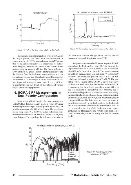
Figure 17. TDR of the dual polar UCIRA-2 (Vertical).By measuring the antenna pattern of the UCIRA-2 onthe major planes, we found that the beamwidth isapproximately 10-12°. The design beamwidth is 20°greaterthan for a parabolic reflector, so it appears that we did notmeet this goal; however, the shape of the antenna is notquite as accurate as we would like. The fabric reflector isapproximately 4.3 cm (1.7 inches) deeper than desired andthe distance from the feed point to the reflector is not asaccurate as we would like. The reflector should be somewhatflatter than it is. This is in spite of several modifications thathave improved the shape to some extent. It is very difficultto compensate for the stretch in the fabric and variouseffects of the sewing operation.6. UCIRA-2 RF Measurements inDual Polarity ConfigurationNext, we provide the results of measurements madeon the UCIRA-2 in dual polarity mode. In Figure 17 we seethat the impedance jumps at the feed point where the 200 Ωtwinline connects to the 400 Ω feed arms. The impedanceshould jump from 50 Ω to 100 Ω in the TDR at this pointdue to the effect of the balun. However, in this case the jumpis not that great. This is perhaps due to losses in the twinlineFigure 18. Normalized impulse responses of the UCIRA-2.that reduce the reflected voltage, so the full effect of theimpedance mismatch is not seen in the TDR.We present the normalized impulse response for bothchannels of the UCIRA-2 in Figure 18. The shape of theimpulse response is not ideal and the FWHM is somewhathigh (108 ps for the vertical channel). This leads to reducedgain at high frequencies as seen in Figure 19. In Figure 20we show the theoretical gain for the UCIRA-2 in dualpolarity mode based on work by Scott Tyo [4, 5]. The gainof the vertical channel of the UCIRA-2 agrees reasonablywell with the predictions, but it falls off more at 10 GHz. Itis interesting that the reduced gain above about 5 GHz isdue to defocusing the reflector and not primarily due toantenna assembly problems as is sometimes the case. Ideallythe gain of the horizontal channel should be the same as thatof the vertical channel; however, as can be seen in Figure 19it is quite different. The differences are due to variations inthe antenna especially at the feed point. At the feed point,two of the wires from separate twinline feeds must cross tobe connected to the tips of the feed arms in the properconfiguration. This requires one wire to be in front of theother, so the wiring cannot be totally identical for the twofeeds.Figure 19. Realized gains of thedual polar UCIRA-2.46The<strong>Radio</strong> <strong>Science</strong> <strong>Bulletin</strong> No <strong>313</strong> (<strong>June</strong>, <strong>2005</strong>)
Figure 20. Theoretical gain ofUCIRA-2.One of our greatest challenges on this project has beenthe construction of the reflector so that it accurately maintainsthe desired hyperbolic shape. A considerable amount ofdispersion results when the path lengths of various rays varyover the surface of the reflector. It is difficult to keep theweight of the antenna minimal, keep the force required toopen the antenna reasonable and still have the stays strongenough to support the fabric reflector in the correct shape.It is also difficult to accurately sew the fabric. Otherconstruction methods and materials may be available, butfor this mechanical deployment scheme a very flexiblematerial such as the conductive rip-stop nylon is required.Thin plastic sheets would probably have a tendency to crackand/or tear during deployment or not lie flat after deployment.Measurements of the antenna patterns for bothchannels in the E and H planes show that the beamwidth inboth planes is approximately 12° - 14°. This is approximatelythe same beamwidth obtained in the standard configuration.This is not surprising since the reflector has not changed. Asmentioned before, the design beamwidth was 20° so we aresomewhat disappointed with this result.By comparing Figure 19 with Figure 16, we see thatthe gain of the antenna in the dual polarity mode is about 2-3 dB less than it is in the standard single feed mode. Thisrelatively small loss, due largely to the impedance mismatchat the feed point, is a small price to pay for adding the dualpolarity capability to the antenna.7. ConclusionsWe built three versions of the Ultra-Compact ImpulseRadiating Antenna, or UCIRA, which was intended forspace applications. The first version, the UCIRA-1, hadelectrical performance that was only slightly less than thatof our commercial CIRA-2. This was a remarkable result,because the UCIRA-1 had a twinline feed instead of thecoaxial cable feed in the CIRA-2. In its collapsed position,the UCIRA-1 was smaller than our commercial CIRA, buta manual operation was required to deploy it. In the UCIRA-1B, we attempted to improve the boresight gain by removingthe negatively contributing portion of the reflector. Thisresulted in performance that was less than that of theUCIRA-1, because the reflector shape came out worse thanbefore.In the final version of the UCIRA, the UCIRA-2, weintroduced a number of improvements. We incorporated anautomatic deployment mechanism, we defocused theaperture to broaden the beam, we allowed for dualpolarization, and we used materials that could be qualifiedfor space operation. Since the feed arms were positioned atequal 90-degree increments around the edge of the reflector,we could feed the antenna either as a single-polarizationantenna with good impedance match, or as a dualpolarization, dual channel antenna with a 2:1 impedancemismatch. When configured as a single-polarization antenna,the gain was considerably less than that of our commercialCIRA-2, because the reflector was defocused into ahyperboloid. When configured as a dual channel antenna,each channel performed well only up to 4-5 GHz, which issufficient for many applications.After studying the various materials that could beused in space applications, the materials used in the UCIRA-2 were very similar to or the same as those used for earliercollapsible antennas. We found a better conductive fabricfor the reflector, and we found that nylon should be asatisfactory fabric for this application. The Tuframâ surfacetreatment on the aluminum was a big improvement. Thisprocess forms a heavy aluminum oxide coating on thealuminum and then a polymer is infused into the surface toform a self-lubricating surface.The development of the balun/twinline feed was amajor success, since the feed for a deployable antenna mustbe very flexible. The attenuation measured for this type offeed was low enough over the frequencies of interest that itcould be used for the satellite application considered here.The<strong>Radio</strong> <strong>Science</strong> <strong>Bulletin</strong> No <strong>313</strong> (<strong>June</strong>, <strong>2005</strong>) 47
- Page 1 and 2: Radio Science BulletinISSN 1024-453
- Page 3 and 4: EditorialJune in December?Yes, this
- Page 5 and 6: URSI Accounts 2004In 2004, a year p
- Page 7 and 8: EURO EUROA2) Routine Meetings 7,315
- Page 9 and 10: URSI AWARDS 2005The URSI Board of O
- Page 11 and 12: Guest Editors’ RemarksOn February
- Page 13 and 14: UWB and the corresponding signal pa
- Page 15 and 16: Radar / CommunicationsBand TypeElec
- Page 17 and 18: of the spectrum is required to comp
- Page 19 and 20: Bandwidths f l / GHz f h / GHz B F
- Page 21 and 22: Figure 3a. A time-domain representa
- Page 23 and 24: Bandwidths f l / f c f h / f c B F
- Page 25 and 26: Bandwidth f l / f c f h / f c B F C
- Page 27 and 28: Quantitative Comparison BetweenMatr
- Page 29 and 30: Next, construct the ‘filtered’
- Page 31 and 32: whereH[ P ] [ U][ ][ V] ,N= Σ (27)
- Page 33 and 34: CPU Time [sec]250200150100MPMSS1SS2
- Page 35 and 36: -10-20MPMSS1SS2-30-40RMSE [dB]-50-6
- Page 37 and 38: RMSE [dB]-45-50-55-60-65-70MPMSS1SS
- Page 39 and 40: An Ultra-Compact Impulse-Radiating
- Page 41 and 42: Figure 3. UCIRA-1 splitter/balun.th
- Page 43 and 44: Figure 9. UCIRA-2 in stowed configu
- Page 45: activated first in the deployment s
- Page 49 and 50: Triennial Reports CommissionsCOMMIS
- Page 51: y the Special Section Editors, and
- Page 55 and 56: 3.2 Activities of URSI-Commission C
- Page 57 and 58: It already has been decided that th
- Page 59 and 60: SCOR (Scientific Committee on Ocean
- Page 61 and 62: COMMISSION GThis triennium report w
- Page 63 and 64: GNSS-LEO occultation is a very impo
- Page 65 and 66: CPEA Contacts: Shoichiro Fukao, Pro
- Page 67 and 68: The group wishes to continue as an
- Page 69 and 70: total of 109 oral papers (24 thereo
- Page 71 and 72: surface, to compensate for the rema
- Page 73 and 74: XXVIIIth General AssemblyNEWLY ELEC
- Page 75 and 76: Décide1. d’accepter l’invitati
- Page 77 and 78: satellite observation, bottomside s
- Page 79 and 80: ETTC ‘05EUROPEAN TEST AND TELEMET
- Page 81 and 82: IRI 2005 WORKSHOPNEW SATELLITE AND
- Page 83 and 84: financial and logistics issues conn
- Page 85 and 86: CONFERENCE ANNOUNCEMENTS36 TH COSPA
- Page 87 and 88: December 2006APMC 2006 - 2006 Asia-
- Page 89 and 90: The Journal of Atmospheric and Sola
- Page 91 and 92: SCIENTIFIC COMMISSIONSCommission A
- Page 93 and 94: Commission E : Electromagnetic Nois
- Page 95 and 96: Commission J : Radio AstronomyChair
- Page 97 and 98:
URSI MEMBER COMMITTEESAUSTRALIA Pre
- Page 99 and 100:
ALPHABETICAL INDEX AND CO-ORDINATES
- Page 101 and 102:
BRUSSAARD, Prof. dr.ir. G., Radicom
- Page 103 and 104:
FEICK, Dr. R., Depto. de Electronic
- Page 105 and 106:
SAUDI ARABIA, Tel. +966 1-4883555/4
- Page 107 and 108:
E-mail loulee@nspo.gov.tw (94)LEE,
- Page 109 and 110:
O’DROMA, Dr. M., Dept. of Electri
- Page 111 and 112:
+30 2310 998161, Fax +30 2310 99806
- Page 113 and 114:
TURSKI, Prof. A., ul. Krochmalna 3
- Page 115 and 116:
Information for authorsContentThe R