It is important to point out that these techniques(MPM, SS1, SS2) are applied directly to the data and not tothe covariance matrix, as information on the noise statisticsrequires additional information that is not available and thenoise in an electromagnetic scene is generated typically byundesired signals in the form of a base-line shift in themeasurement hardware instead of thermal background noise.In addition, a deterministic model produces a lower Cramer-Rao bound than a stochastic model for the estimation of theparameters of interest. For these reasons, the authors feelthat a deterministic approach is at least as applicable, if notmore so, to modeling radar returns with stochasticapproaches.7. References1. Y. Hua and T. K. Sarkar, “On SVD for Estimating GeneralizedEigenvalues of Singular Matrix Pencil in Noise,” IEEE Trans.On Signal Processing, 39, 4, 1991, pp. 892-900.2. Y. Hua and T. K. Sarkar, “Matrix Pencil Method for EstimatingParameters of Exponentially Damped/ Undamped Sinusoidsin Noise,” IEEE Trans. Acoustics, Speech, and Signal Processing,38, 5, May 1990, pp. 814-824.3. Y. Hua and T. K. Sarkar, “Matrix Pencil and System Poles,”Signal Processing, 21, 2, Oct. 1990, pp. 195-198.4. Y. Hua and T. K. Sarkar, “On SVD for Estimating GeneralizedEigenvalues of Singular Matrix Pencil in Noise,” IEEE Trans.Acoustics, Speech, and Signal Processing, 39, 4, April 1991,pp. 892-900.5. Y. Hua and T. K. Sarkar, “Parameter Estimation of MultipleTransient Signals,” Signal Processing, 28, 1992, pp. 109-115.6. F. Hu, Y. Hua, and T. K. Sarkar, “Utilization of BandpassFiltering for the Matrix Pencil Method,” IEEE Trans. SignalProcessing, 41, 1, 1993, pp. 442-446.7. B. D. Rao, “Relation between Matrix Pencil and State SpaceBased Harmonic Retrieval Methods,” IEEE Trans. Acoustics,Speech, and Signal Processing, 38, 1, 1990, pp. 177-179.8. S. Y. Kung, “A New Identification and Model ReductionAlgorithm via Singular Value Decompositions,” Proc. TwelfthAsilomar Conf. on Circuits, Systems and Computers, November6-8, 1978, Monterey, California, pp. 705-714.9. T. K. Sarkar and O. Pereira, “Using the Matrix Pencil Methodto Estimate the Parameters of a Sum of Complex Exponentials,”IEEE Antennas and Propagation Magazine, 37, 1, 1995, pp.48-55.10.E.-J. Ang, V. Sreeram, and W. Q. Liu, “Identification/Reductionto a Balanced Realization via the Extended ImpulseResponse Grammian,” IEEE Trans. Automatic Control, 40,12, pp. 2153-2158.11.P. Agathoklis and V. Sreeram, “Identification and ModelReduction from Impulse Response Data,” Int. J. System <strong>Science</strong>,21, 8, 1990, pp. 1541-1552.12.V. Sreeram and P. Agathoklis, “On the Computation of theGram Matrix in Time Domain and Its Application,” IEEETrans on Automatic Control, AC-38, 10, 1993, pp. 1516-1520.13.Y. Hua and T. K. Sarkar, “A Note on the Cramer-Rao Boundfor 2-D Direction Finding Based on 2-D Array,” IEEE Trans.Signal Processing, 39, 5, May 1991, pp. 1215-1218.14.C. D. Meyer, Matrix Analysis and Applied Linear Algebra,Society for Industrial and Applied Mathematics, Philadelphia,2000, p. 412.15.B. M. Kolundzija, J. S. Ognjanovic, and T. K. Sarkar, WIPL-D (for Windows manual): Electromagnetic Modeling ofComposite Metallic and Dielectric Structures, Artech House,Norwood, MA, 2000.16.T. K. Sarkar, W. Lee, and S. M. Rao, “Analysis of TransientScattering From Composite Arbitrarily Shaped Complex Structures,”IEEE Trans. Antennas and Propagation, 48, 10, Oct.2000, pp. 1625-1634.38The<strong>Radio</strong> <strong>Science</strong> <strong>Bulletin</strong> No <strong>313</strong> (<strong>June</strong>, <strong>2005</strong>)
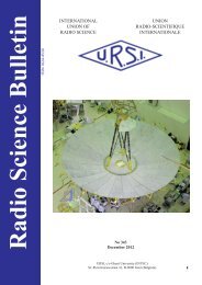
An Ultra-Compact Impulse-Radiating AntennaL.H. BowenE.G. FarrD.I. LawryJ.S. TyoAbstractWe describe the development of an ultra-compactimpulse-radiating antenna (UCIRA), intended for spaceapplications in low Earth orbit. Because a UWB (ultrawideband)antenna was desired for this application, an IRA(impulse-radiating antenna) was selected as the startingpoint for this development. The standard IRA configurationhas a single linear polarization, and has a very narrowbeamwidth at high frequencies. A dual-polarization antennawas desired with a larger beamwidth, so we modified theexisting design to support dual polarization, and we used ahyperbolic reflector to increase the beamwidth. The antennaalso had to survive the harsh space environment, had to belightweight and very compact for launch, and had to beremotely deployable.A deployable IRA with dual polarization using aflexible twinline feed has been developed that has verygood RF characteristics. Also, the theory for IRAs withhyperbolic reflectors and defocused feeds has been advanced.The UCIRA-2 developed here met many of the requirements.1. IntroductionWe summarize here our efforts to build an Ultra-Compact Impulse Radiating Antenna (UCIRA) for spaceapplications. This may be considered an extension of ourearlier work to develop an IRA for space applicationsfabricated from an inflatable membrane [1]. We subsequentlydecided that the inflatable technology was only appropriatefor very large antennas. For the smaller antennas in whichwe were interested, a mechanically deployable antennawould be more durable. An example of such an antenna isthe commercially available CIRA-2 [2, 3], with a diameterof 1.22 m (48 in.). However, the stowed size of the CIRA-2 was too large for satellite applications. This led to thedevelopment of the Ultra-Compact IRA or UCIRA, whichis described here.The UCIRA differs from the CIRA-2 in five respects.First, we reduced the collapsed length from 81 cm (32 in.)in the CIRA to 48 cm (19 in.). This was accomplished byreducing the F/D (focal length / diameter) ratio from 0.4 to0.3, and by adding a folding joint to each of the 12 radialsupport rods in the reflector. Second, we defocused thebeam with a hyperboloidal reflector, so we could see alarger field of view from low earth orbit (LEO). Third, weconfigured the antenna to operate with dual polarity. Fourth,we made the antenna automatically deployable with springsand electro-mechanical elements. Fifth, we used materialsthat could qualify for space applications.The UCIRA is intended to provide as wide a coveragearea as possible from a satellite platform in LEO. In orderto receive signals from horizon to horizon, the antennaneeds to have a beamwidth of 100° to 120°. Since IRAs areinherently highly directional (narrow beamwidth) at highfrequencies, the UCIRA must be defocused using ahyperboloidal reflector instead of a parabolic reflector asdescribed in [4, 5]. We also wanted the bandwidth to be verybroad, and a design based on an IRA is well suited for thisdue to its approximately 2 decades of bandwidth. TheCIRA-2, on which the UCIRA is based, is usable from150 MHz to 10 GHz [3]. In addition, we wanted the antennato have dual polarity, so twice the information is availablefrom a single antenna.To study dual polarity IRAs, we experimented witha 46 cm (18 in.) diameter solid aluminum IRA which hadtwo feeds, one for each polarity, vertical and horizontal.This antenna was the IRA-1D. The results of this dualpolarity experiment were reported previously in [6].It has been noted previously by Carl Baum [7] thata hyperboloidal reflector with a circular rim may have aproblem in its radiated frequency spectrum on boresight.This occurs at the frequency where the difference in ray pathlengths from the center and edge of the reflector is half awavelength. To address this problem, he proposed using aLeland H. Bowen is with Farr Research, Inc., 8 Ridge Road,Placitas, NM 87043 USA; Tel: +1 (505) 867-2731; Fax: +1(505) 867-9125; E-mail: lhbowen@farr-research.com.Everett G. Farr is with Farr Research, Inc., 614 Paseo DelMar NE, Albuquerque, NM 87043 USA;Tel: +1 (505) 293-3886; Fax: +1 (505) 323-1886; E-mail:efarr@farr-research.com.Dean I. Lawry is with the Air Force Research Laboratory/DE, 3550 Aberdeen Ave. SE, Kirtland AFB, NM 87117-5776 USA; Tel: +1 (505) 853-3392.J. Scott Tyo is with the University of New Mexico, EECEBuilding, Room 125, University of New Mexico,Albuquerque, NM 87131-1356 USA; Tel: +1 (505) 277-1412; Fax: +1 (505) 277-1439, E-mail tyo@ece.unm.eduThe<strong>Radio</strong> <strong>Science</strong> <strong>Bulletin</strong> No <strong>313</strong> (<strong>June</strong>, <strong>2005</strong>) 39
- Page 1 and 2: Radio Science BulletinISSN 1024-453
- Page 3 and 4: EditorialJune in December?Yes, this
- Page 5 and 6: URSI Accounts 2004In 2004, a year p
- Page 7 and 8: EURO EUROA2) Routine Meetings 7,315
- Page 9 and 10: URSI AWARDS 2005The URSI Board of O
- Page 11 and 12: Guest Editors’ RemarksOn February
- Page 13 and 14: UWB and the corresponding signal pa
- Page 15 and 16: Radar / CommunicationsBand TypeElec
- Page 17 and 18: of the spectrum is required to comp
- Page 19 and 20: Bandwidths f l / GHz f h / GHz B F
- Page 21 and 22: Figure 3a. A time-domain representa
- Page 23 and 24: Bandwidths f l / f c f h / f c B F
- Page 25 and 26: Bandwidth f l / f c f h / f c B F C
- Page 27 and 28: Quantitative Comparison BetweenMatr
- Page 29 and 30: Next, construct the ‘filtered’
- Page 31 and 32: whereH[ P ] [ U][ ][ V] ,N= Σ (27)
- Page 33 and 34: CPU Time [sec]250200150100MPMSS1SS2
- Page 35 and 36: -10-20MPMSS1SS2-30-40RMSE [dB]-50-6
- Page 37: RMSE [dB]-45-50-55-60-65-70MPMSS1SS
- Page 41 and 42: Figure 3. UCIRA-1 splitter/balun.th
- Page 43 and 44: Figure 9. UCIRA-2 in stowed configu
- Page 45 and 46: activated first in the deployment s
- Page 47 and 48: Figure 20. Theoretical gain ofUCIRA
- Page 49 and 50: Triennial Reports CommissionsCOMMIS
- Page 51: y the Special Section Editors, and
- Page 55 and 56: 3.2 Activities of URSI-Commission C
- Page 57 and 58: It already has been decided that th
- Page 59 and 60: SCOR (Scientific Committee on Ocean
- Page 61 and 62: COMMISSION GThis triennium report w
- Page 63 and 64: GNSS-LEO occultation is a very impo
- Page 65 and 66: CPEA Contacts: Shoichiro Fukao, Pro
- Page 67 and 68: The group wishes to continue as an
- Page 69 and 70: total of 109 oral papers (24 thereo
- Page 71 and 72: surface, to compensate for the rema
- Page 73 and 74: XXVIIIth General AssemblyNEWLY ELEC
- Page 75 and 76: Décide1. d’accepter l’invitati
- Page 77 and 78: satellite observation, bottomside s
- Page 79 and 80: ETTC ‘05EUROPEAN TEST AND TELEMET
- Page 81 and 82: IRI 2005 WORKSHOPNEW SATELLITE AND
- Page 83 and 84: financial and logistics issues conn
- Page 85 and 86: CONFERENCE ANNOUNCEMENTS36 TH COSPA
- Page 87 and 88: December 2006APMC 2006 - 2006 Asia-
- Page 89 and 90:
The Journal of Atmospheric and Sola
- Page 91 and 92:
SCIENTIFIC COMMISSIONSCommission A
- Page 93 and 94:
Commission E : Electromagnetic Nois
- Page 95 and 96:
Commission J : Radio AstronomyChair
- Page 97 and 98:
URSI MEMBER COMMITTEESAUSTRALIA Pre
- Page 99 and 100:
ALPHABETICAL INDEX AND CO-ORDINATES
- Page 101 and 102:
BRUSSAARD, Prof. dr.ir. G., Radicom
- Page 103 and 104:
FEICK, Dr. R., Depto. de Electronic
- Page 105 and 106:
SAUDI ARABIA, Tel. +966 1-4883555/4
- Page 107 and 108:
E-mail loulee@nspo.gov.tw (94)LEE,
- Page 109 and 110:
O’DROMA, Dr. M., Dept. of Electri
- Page 111 and 112:
+30 2310 998161, Fax +30 2310 99806
- Page 113 and 114:
TURSKI, Prof. A., ul. Krochmalna 3
- Page 115 and 116:
Information for authorsContentThe R


