

MCP3421 - Microchip
MCP3421 - Microchip
MCP3421 - Microchip

You also want an ePaper? Increase the reach of your titles
YUMPU automatically turns print PDFs into web optimized ePapers that Google loves.
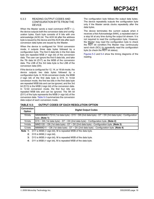
<strong>MCP3421</strong>5.3.3 READING OUTPUT CODES ANDCONFIGURATION BYTE FROM THEDEVICEWhen the Master sends a read command (R/W = 1),the device outputs both the conversion data and configurationbytes. Each byte consists of 8 bits with oneacknowledge (ACK) bit. The ACK bit after the addressbyte is issued by the device and the ACK bits after eachconversion data bytes are issued by the Master.When the device is configured for 18-bit conversionmode, it outputs three data bytes followed by aconfiguration byte. The first 6 data bits in the first databyte are repeated MSB (= sign bit) of the conversiondata. The user can ignore the first 6 data bits, and takethe 7th data bit (D17) as the MSB of the conversiondata. The LSB of the 3rd data byte is the LSB of theconversion data (D0).If the device is configured for 12, 14, or 16 bit-mode, thedevice outputs two data bytes followed by aconfiguration byte. In 16 bit-conversion mode, the MSB(= sign bit) of the first data byte is D15. In 14-bitconversion mode, the first two bits in the first data byteare repeated MSB bits and can be ignored, and the 3rdbit (D13) is the MSB (=sign bit) of the conversion data.In 12-bit conversion mode, the first four bits arerepeated MSB bits and can be ignored. The 5th bit(D11) of the byte represents the MSB (= sign bit) of theconversion data. Table 5-3 summarizes the conversiondata output of each conversion mode.The configuration byte follows the output data bytes.The device repeatedly outputs the configuration byteonly if the Master sends clocks repeatedly after thedata bytes.The device terminates the current outputs when itreceives a Not-Acknowledge (NAK), a repeated start ora stop bit at any time during the output bit stream. It isnot required to read the configuration byte. However,the Master may read the configuration byte to checkthe RDY bit condition.The Master may continuouslysend clock (SCL) to repeatedly read the configurationbyte (to check the RDY bit status).Figures 5-3 and 5-4 show the timing diagrams of thereading.TABLE 5-3:ConversionOption18-bitsOUTPUT CODES OF EACH RESOLUTION OPTIONDigital Output CodesMMMMMMD17D16 (1st data byte) - D15 ~ D8 (2nd data byte) - D7 ~ D0 (3rd data byte) - Configurationbyte. (Note 1)16-bits D15 ~ D8 (1st data byte) - D7 ~ D0 (2nd data byte) - Configuration byte. (Note 2)14-bits MMD13D ~ D8 (1st data byte) - D7 ~ D0 (2nd data byte) - Configuration byte. (Note 3)12-bits MMMMD11 ~ D8 (1st data byte) - D7 ~ D0 (2nd data byte) - Configuration byte. (Note 4)Note 1: D17 is MSB (= sign bit), M is repeated MSB of the data byte.2: D15 is MSB (= sign bit).3: D13 is MSB (= sign bit), M is repeated MSB of the data byte.4: D11 is MSB (= sign bit), M is repeated MSB of the data byte.© 2009 <strong>Microchip</strong> Technology Inc. DS22003E-page 19


