
Create successful ePaper yourself
Turn your PDF publications into a flip-book with our unique Google optimized e-Paper software.
<strong>Emeter</strong> v2 <strong>Quick</strong> <strong>Guide</strong> 2.07 rev. Jan 14 2008See http://media.hyperion.hk/dn/em2 for updates to documentation, PC software, and FirmwareIntroductionThe <strong>Hyperion</strong> <strong>Emeter</strong> II can carry out an enormous range of functions related to Electric Powered models andsmall vehicles, and has been designed with ease of use as a prime objective. On-screen help, a menu systemand friendly error messages all contribute to this objective while in the field or at the lab.This <strong>Quick</strong> <strong>Guide</strong> describes the scope of <strong>Emeter</strong> II and how to make it work for you, in a sequence whichmatches the on-screen menus. The <strong>Emeter</strong>’s own On-screen help is a subset of this information intended toanswer most questions at the field. The full <strong>Emeter</strong> II User Manual (Download from link above) goes intogreater depth with explanations of many of the issues surrounding Electric Power and Radio Control models.The <strong>Emeter</strong> II System consists of two major components:• The pocket sized case houses the display screen, an SD Card slot, buttons for menu navigation, apotentiometer to drive pulse-width devices such as servos and motor controllers, an optical tachometer,and an internal battery pack with onboard charger.• A Remote Data Unit which, with its small size can be fitted to the power system (RC model, robot,scooter, etc…) to log data. At the end of the logging period, the captured data can be copied to the<strong>Emeter</strong> II for display, without the need for a Personal Computer.In addition, the <strong>Emeter</strong> v2 comes with two cables in the box:-- A Data Cable (aka “RDU Cable”, #HP-EM2-4PINCBL). It has a locking Molex 4-pin connector on one sidewhich fits the <strong>Emeter</strong> v2 at bottom-right port. The other side has 5-pin female connector (with one pin“blanked”). This side fits the RDU so that the RDU can transfer files to <strong>Emeter</strong>, and communicate during Benchtesting or RDU setup. The same side also fits <strong>Hyperion</strong> TITAN series ESC, for programming via <strong>Emeter</strong>.-- A Power Cable (#HP-EM2-PWRCBL) with 4.5mm plug on one side, and tinned wires on the other. The<strong>Emeter</strong> contains a 5-cell 750mAh NiMH battery inside, and an INTERNAL CHARGER. You should never connecta battery charger to this power input. Instead, simply use any 12V~15V DC power supply with 120mA orhigher capacity (such as a 13.8V DC power supply, Automotive battery, or discarded 12V “Wall PS” from someold toy, router, etc). Please take time now to fit appropriate connectors to this cable, and plug in your<strong>Emeter</strong> to a 12-15V power source for charging. See details below for charge rate and time.TerminologyRDU – The Remote Data Unit contains data storage, and sensors for measuring voltage, current, height(altitude from start point), ambient temperature and other data. In addition the RDU has input/outputconnectivity to a receiver or pulse-width driver such that throttle position can be recorded or remote on/off oflogging controlled. The RDU can record peak currents up to 150A with stock wiring (up to 300A, 5 sec,modified), with a maximum of 70V input. There are also optional sensors available for up to three externaltemperatures and phase tachometer for brushless motors at this time, with other sensors planned for 2009.Before using the RDU, it is necessary to solder on the connectors of your choice to the RED/BLACK wiresmarked INPUT (Battery, DC PS) and LOAD (Motor, Charger, Discharger, etc) on RDU bottom. The connectorsmust be high-quality and matched in size to the maximum currents you expect to draw. Although the RDU isprotected against accidental connection with polarity reversed, the ESC which is normally connected to theLOAD side of the RDU, is likely not protected and will be destroyed by reversed polarity. So take great care withconnector polarity.ESC - Electronic Speed Controller is used to vary the speed of the model’s motorsBEC - Battery Eliminator Circuitry, optionally included in the ESC, is used to power receiver/servos from mainpower pack instead of a separate receiver packSD Card – is a mass data storage device which may also be used for transfer of data between a PC and the<strong>Emeter</strong> II, including:• <strong>Emeter</strong> II and RDU firmware updates• Files for On-line screen help• Prop constants data• Data logs• Parameters for user-programmable servo or ESC driversAn SD card is not included but is strongly suggested for complete functionality. Standard (or Mini/Micro in adapter) SD SDHCcards up to 4Gb are supported. They must be formatted as FAT16 or FAT32.Phase Tachometer sensor – (option part # HP-EM2-TACHBL) has a single wire which should be connected toany of the three wires into a brushless motor, and the 3 pin plug which fits the RDU socket labelled ‘RPM’.External Temp 1,2,3 sensors – (option parts #HP-EM2-TMP1 and #HP-EM2-TMP23) Note that Temp#1 mustbe purchased in order to add temps #2 and #3, as only TEMP#1 connects direct to RDU (2,3 connect with #1).
On Screen Help and NavigationFeatures are accessed by selection from a multi-level menu. Button numbers are shown in quotes for example‘A’, ‘B’, ‘C’ or ‘D’ and have an abbreviated description on the bottom row of the display. Button ‘A’ on the MAINmenu will display Tips on RDU and <strong>Emeter</strong> II firmware version upgrades. Navigation through the menus isachieved by pressing ‘D’ until the required menu item shows in larger characters. Once this occurs,• press ‘B’ to display screen help relating to the selected function or• press ‘C’ to go to the selected function.There are two basic modes of operation – ‘Bench-Test’ mode in which the RDU and the <strong>Emeter</strong> II are connectedfor use together, and ‘In-Action’ mode where the RDU is used alone. In Bench-Test mode, data is recordeddirectly to the SD card, whereas In-Action mode stores the data in the RDU from where it is later copied to the<strong>Emeter</strong> II SD card. After switching the <strong>Emeter</strong> II on, the function which was in use at the previous switch offtime will re-appear. In most cases, ‘A’ will cause a return to the previous, higher menu item or screen. Certainactions may cause deletion of data which could be critical. You will be warned if this is the case and requestedto confirm the action.OPERATION NOTESEMETER BASIC SETUPFunction Screen/Mode Cables/Wiring1.1 Internal battery Charging 12-15 volt supply with the supplied 4.5mm plugThe <strong>Emeter</strong> II will automatically charge while connected to 12-15V PS whether the unit is in use, or switched off.The <strong>Emeter</strong> can be used while connected to 12-15V power source (i.e. during bench testing can be left connected)Charging will occur at 85 ma and take 9 - 12 hours at this rate from a fully discharged state.The battery will last between 18 and 50 hours, depending on use of screen backlight, connection to RDU and other factors.Main menu shows internal battery charge state indicator. Reconnect to 12-15V PS before this falls to 0%. The date and timewill need to be reset if the internal battery is allowed to go flat.1.2 Set Date/Time MAIN>EMETER SETUPPress ‘D’ (next) to move to date or time lines.Press ‘B’ or ‘C’ to decrease or increase the fields as required. Hold button down for accelerated change.These fields are used to add a timestamp to log files or snapshots (see 4.1 – 4.3).
EMETER BASIC SETUP continuedFunctionScreen/Mode1.3 Screen Backlight MAIN>EMETER SETUPPress ‘D’ to move to LCD Light line and pick‘Off’ for no backlight‘On’ for constant backlight‘Auto’ for backlight on for 10 seconds duration whenever a button is pushedDefault setting is ‘Auto’.1.4 Contrast MAIN>EMETER SETUPPress ‘D’ to move to Contrast and pick a number between 15 and 30 for desired effect.1.5 Button Beeps MAIN>EMETER SETUPPress ‘D’ to move to Beeps and pick ‘On’ or ‘Off’ for a ‘click’ or ‘beep’ each time a button is pressed . Default setting is ‘On’.1.6 Height & Temperatures MAIN>EMETER SETUPSystem holds figures in Metres and Celsius and will convert and display Feet and Fahrenheit if so specified here.INSTANTANEOUS READINGS (and Tacho Setup)Function Screen/Mode Cables/Wiring2.1 Tacho - configure Optical Tach READINGS>TACHO>push ‘C’ > CONFIG TACHO NoneSet Tacho Source as <strong>Emeter</strong> by pressing ‘B’ or ‘C’. Press ‘D’ and set blades as 1 to 6.Without the RDU connected, the source will be set to <strong>Emeter</strong> automatically.-- Set Tacho averaging:On averages rpm over 2 secs if < 9,000 rpm. Averages rpm over 1 sec if > 9,000 rpmOff averages over 1 sec always.Press ‘A’ to save tacho configuration2.2 Tacho: configure Phase Sen.TachREADINGS>TACHO>push ‘C’ > CONFIG TACHO*The RDU Tacho is for brushless motors and ESC only *RDU + RDU cable +Phase TachWith the <strong>Emeter</strong> II, RDU and the phase sensor pick-up lead connected, the source can be selected as either• <strong>Emeter</strong> II for the optical tacho or• RDU for the phase sensor tachoFor RDU, the number of Motor Magnets must be set or erroneous results will occur. Set Gearbox ratio (“1” for direct drive)2.3 Determine Motor Magnet Count READINGS>TACHO push ‘C’ > CONFIG TACHO RDU + RDU cable +Phase TachRun the motor at steady speed with <strong>Emeter</strong> II close to spinning prop.Vary no. of magnets until the RDU and <strong>Emeter</strong> II Opto rpm figures match and Save configuration.2.4 Tacho - Read RPM optical READINGS>TACHO NoneHold top of <strong>Emeter</strong> II about 10 cm from rotating prop. Wait until readings steady. Avoid fluorescent lightsPress ‘D’ to hold reading (see sect 4.1). Press ‘C’ to save reading to SNAPSHOT 1-8 (see section 4.3)Press ‘B’ to set prop constants, if known and show motor output power (see section 5)2.5 Tacho – Read phase sensor RPM READINGS>TACHO orREADINGS>ANALYSERRDU + RDU cable+ rpm sensor cableConnect rpm sensor lead to RDU RPM socket and to any of the 3 wires of brushless motor. * Do not use on brushed motors *2.6 Read Volts Bench-Test READINGS>ANALYSER RDU + RDU cable0 to 70 volts, 2 dec. places2.7 Read Amps Bench-Test READINGS>ANALYSER RDU + RDU cable0 to 150 amps peak, 1 dec. place. BATTERY shows voltage, max. and min. and ma-h energy input and output (charge &discharge)2.8 Watts into ESC/Motor READINGS>ANALYSER RDU + RDU cable0 - 10000 watts, calculated as the product of Volts * Amps2.9 Motor/ESC Efficiency READINGS>ANALYSER RDU + RDU cableDisplays efficiency if Prop Constants in place and less than 100%. Press ‘D’ to hold values on screen. Press ‘C’ to save valuesin SNAPSHOT 1–82.10 Motor Output Power & Thrust READINGS>TACHO NoneDisplay power in Watts and BHP and thrust in grams if propeller constants exist for the given prop.2.11 Height READINGS>ANALYSER RDU + RDU cableThe height sensor is fitted in the RDU and is set to zero metres when power is connected to the RDU. Position in model mayaffect readings. See <strong>Emeter</strong> II manual for more.
ACCUMULATED and PEAK DATAFunction Screen/Mode Cables/Wiring3.1 Capacity mAh Input READINGS>BATTERY or READINGS>ANALYSERAccumulates even when on other screensRDU + RDU cableFrom 0 – 65000 mA-h. Records charged capacity automatically, whenever current is flowing through the RDU. Press ‘C’ to clearmA-h In when on BATTERY screen. NOTE: Capacity will continue to log in the RDU even if the <strong>Emeter</strong> II is switched off.3.2 Capacity mAh Output READINGS>BATTERY or READINGS>ANALYSERAccumulates even when on other screensRDU + RDU cableFrom 0~65000 mA-h. Records discharged capacity automatically, whenever current is flowing through the RDU. Press ‘C’ to clearmA-h ‘Out’ when on BATTERY screen. Note: Capacity will continue to log in the RDU even if the <strong>Emeter</strong> II is switched off.3.3 Max Volts READINGS>PEAKS RDU + RDU cablePeak values recorded for whole session or from when ‘B’ (Clr) pressed. These values are lost when switching the <strong>Emeter</strong> II offunless saved to SNAPSHOT 1 – 83.4 Min Volts READINGS>PEAKS RDU + RDU cableAs above. Useful to assist in protecting batteries from over-discharge.3.5 Max Amps READINGS>PEAKS RDU + RDU cableAs above. Useful to assist in protecting batteries and ESC from over-current conditions.3.6 Max RPM READINGS>PEAKS RDU + RDU cablePeak values recorded for whole session or until ‘B’ (Clr) pressed.3.7 Pack resistance Ohms READINGS>PEAKS RDU + RDU cableStart discharge, press ‘B’ (Clr), stop discharge or Press ‘B’ (Clr), start and stop discharge. Resistance will be shown in ohmsSNAPSHOTS for short term saving of readings4.1 Hold Display On TACHO, PEAKS, ANALYSER, BATTERY screens RDU + RDU cablePress ‘D’ to hold – 2 nd press continues, as if no hold took place4.2 Save snapshot As for Hold RDU + RDU cablePress ‘C’ to save in one of 8 SNAPSHOT locations for later recall, select SNAPSHOT 1 to 8 by pressing ‘D’, if required.Press ‘C’ again to resume original activity. Data stored in first empty SNAPSHOT location by default. Snapshots are retained whenthe <strong>Emeter</strong> II is turned off, but for long term data retention, see data logging facility4.3 Snapshot Recall-Clear READINGS>SNAPSHOTS NoneShows up to 8 snapshots taken from ANALYSER, BATTERY, SNAPSHOTS or TACHO screens These are stored internally, not on theSD card. Press ‘D’ to scroll through snapshot 1 to 8. Display is in format of screen from which the save was originally made.For ANALYSER or TACHO data press ‘B’ to view or specify Prop. constants. If these exist, then the calculated efficiency and/orpropeller thrust in grams will show. Clear snapshot by pressing ‘C’PROP CONSTANTS for calculation of motor efficiency and thrustFunction Screen/Mode Cables/Wiring5.1 Prop Constant BackgroundProp constants can be used to calculate motor/ESC power/efficiency and also thrust for given RPM. See PROP TALK tutorial in<strong>Hyperion</strong> Website at www.hyperion.hk/dn/em2 . <strong>Emeter</strong> II can look up prop constants from a PROPS.TXT file held on the SD Cardor will accept constants entered manually onto the CONSTANTS screen. The latter are given the name ‘Other’. For either case, thelast-used propeller details are retained for subsequent power, efficiency and thrust calculations5.2 Prop Constant Viewing READINGS>PROP CONST orREADINGS>ANALYSER> button ‘B’ (Prop) orREADINGS>TACHO> button ‘B’ (Prop)SD CardIf SD Card contains PROPS.TXT file, browse props via buttons ‘B’ (Dec) and ‘C’ (Inc). To select required file press ‘A’ (Save)5.3 Prop Constant Entry READINGS>PROP CONST orREADINGS>ANALYSER> button ‘B’ (Prop) orREADINGS>TACHO> button ‘B’ (Prop)Press ‘D’ (next) to move to Power Constant field, use ‘D’ to move to figure to be entered and ‘B’ or ‘C’ to change to required value.Use ‘D’ to move to next figure and repeat process in the same way. Once numbers are correct, press ‘A’ to save for all futurecalculations until changed and saved again. Prop name will change to ‘Other’5.4 Prop Constant Entry NotesMotor output power, efficiency and thrust figures are not calculated for In-Action mode since propeller constants do not apply tomoving models. Only Bench-test mode can record power, efficiency and thrust. See manual for details.
DATA LOGGING for long term save of dataFunction Screen/Mode Cables/Wiring6.1 Data Logging Bench-TestmodeREADINGS>ANALYSER orREADINGS > BATTERYRDU + RDU cable + optional RPM ortemperature sensorsPress ‘C’ to log readings to SD card or to cease logging under full user control. Each start creates a new log file with unique filenumber and showing date and time. Blinking message on screen acts as recording indicator.Warning, do NOT power off the <strong>Emeter</strong> II while logging is in progress.Press ‘C’ on BATTERY or ANALYSER screens to stop logging first.6.2 Set RDU data loggingparameters for the In-Action modeMAIN MENU>RDU SETUPRDU + RDU cableSet Trigger type for start of logging:• Amps – start logging when actual current exceeds specified trigger ampsIf amps fall below trigger level, then logging will stop if the EXPIRY TIME has elapsed.• Increase amps above trigger current to resume logging. There will be multiple sets of data readings – one set for each time theactual current rises above then falls below the specified trigger amps. These different sets will all be down-loaded to the SDcard as a single file. The time display resets to 0 at the start of each set. For continuous logging after amps start, set expiryrecord time = 0 or very high. If the RDU is unplugged from the main power source, then, once the RDU and power source arere-connected, a new data log file will be created. The download action, if chosen, will copy all files from the RDU to the SD card• Time – this option is used for motor-less models which cannot use an AMPS based trigger. Logging begins once start delayseconds have elapsed after RDU connected to main Power Pack and continues until the RDU is disconnected or the record timeexpires• Manual – logging controlled by signal from spare receiver channel. Pulse width < 1300 μs. will stop logging and > 1700 μsstarts loggingSet recording expiry time (in secs.) for data logging session or zero for unlimited lengthSet sample rate from 4 per second to 8 secs. per sample. This sample rate applies to both In-Action and Bench-Test modes.Save logging parameters by pressing ‘A’6.3 Set up RDU logging of:RDU + optional RPM and temperature sensorsAmps, Volts, RPM, Ambienttemp, 3 other temps,heightNO RDU cable from RDU to <strong>Emeter</strong> II3 wire cable from spare Rx channel to RDURx input (for manual logging start)- Connect optional rpm sensor to RDU RPM port and any one of brushless motor input leads. Note that the ambient temperatureand height will be recorded automatically by sensors built in to the RDU. Connect option temp. sensor #1 to the 4 pin plug on theRDU marked ‘AUX’, and connect option Temps #2 and #3 to Temp #1. Where possible, use adhesive tape to prevent movementbetween the sensors and target to ensure good contact (example, motor, power pack and ESC).- Connect RDU main power wires to ESC. When ready to run model, connect RDU to power pack. Green LED should flash on RDUat the sample rate. Green LED changes to red whilst logging is in progress. Time based logging will stop when the Record Secs. onthe RDU SET-UP have elapsed or the RDU is disconnected from the model’s power-pack.Amps triggered logging will stop when the Record Secs have elapsed AND the current drops below the trigger amps.Logging will resume again if the current rises above the trigger amps; a fresh Record Secs time will apply6.4 DownloadData to <strong>Emeter</strong> IIAt switch on-time an automatic messageappears if RDU carries data which has notbeen downloadedConnect RDU to <strong>Emeter</strong> II via RDU cableSwitch <strong>Emeter</strong> II on – should receive message ‘found dataset – download now?’RDU + SD Card + RDU cableReply ‘Yes’ by pressing ‘D’ or ‘A’ to defer the transfer of data held in the RDU until laterThe progressive status of download is shown and the data is downloaded to the SD Card with a unique file number and showing thedate and time of the download6.5 View log files MAIN>LOG FILES SD CardUse ‘D’ to browse to required log file. Log files have a unique file number and show the date and time stamps which are set to thedate and the time of:• the download from RDU to <strong>Emeter</strong> II or• the time when a Bench-Test log file was createdLogged data for both In-Action and Bench-Test consists of:TimeVoltsAmpsRpmWatts InputHeight6.6 Graphing of log files MAIN>LOG FILES SD CardMa-h outMa-h InAmbient TempSensor 1 tempSensor 2 tempSensor 3 tempAfter highlighting a Log File from the list, press ‘C’ to select. The Graph function will allow any two of volts, amps, height and rpmto be plotted against time. For full details, refer to <strong>Emeter</strong> II Manual.
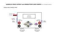
TIMERS & STOPWATCHESGeneral notes on Timers and Stopwatches - On entering any one of the three stopwatch screens, a check is made for anyprevious timing data for this particular stopwatch mode. If this exists, then the stopwatch will display the previous data. If thedata was initially captured using a different stopwatch mode, then a warning is issued and the option to clear data is given. Allstopwatch and countdown functions will remain running while using other <strong>Emeter</strong> II screens.Function Screen/Mode Cables/Wiring7.1 Stopwatch/lap count mode MAIN>STOPWATCHES>LAP COUNT NoneUse to time any competition for which individual lap times and counts are needed. Records up to 100 ‘events’ which may be laptimes or stopwatch starts/stops.Start stopwatch with Button D - shows time as Primary (PRIM)Press button C at end of each lap. Lap time and the lap number show on lower half of screen.SPLT is the value of Primary time as of last button C press.Press button D to pause both Primary and lap timers.Press ‘C’ to recall laps from beginning7.2 Stopwatch- Dual Mode MAIN>STOPWATCHES>DUAL MODE NoneUse for timing one activity within a second for example one individual lap within a multi-lap raceUse ‘C’ to start/stop the secondary stopwatch and ‘D’ for primary stopwatchSecondary watch only runs whilst primary is runningAll events such as watch starts and stops are included in the list and may be recalled later if the <strong>Emeter</strong> II is switched to anotherfunction7.3 Stopwatch-Auto Mode MAIN>STOPWATCHES>AUTO MODE NoneSame as Dual Mode, except that a single push of ‘D’ will automatically start both watches7.4 Count Down Timer MAIN>STOPWATCHES>COUNT DOWN NonePress ‘B’ (set) followed by ‘B’ or ‘C’ (increase or decrease) to change countdown start time. Hold these buttons down foraccelerated change.Press ‘D’ to save – current time will be reset to countdown start time.Press ‘D’ to start countdown and ‘D’ a second time to stop/pause if required.When the countdown timer is running, pressing ‘A’ will allow use of most other <strong>Emeter</strong> II functions, such as Tacho or servo testwithout interrupting the countdown.At the end of the specified time:A 3-second-long beep will sound even if the <strong>Emeter</strong> II is in use on a different screen/functionThe current time will start increasing ‘TIME OVER’ will be displayedSERVO and ESC programming and testing8.1 Titan ESC Programmer MAIN>PROGRAMMING>TITAN PROG Unplug <strong>Emeter</strong> II-RDU cable from RDUPlug RDU cable into ESCConnect 4 wire cable from <strong>Emeter</strong> II to ESC and press ‘D’ (connect).<strong>Emeter</strong> II will display all settings which may be changed. If display fails to appear, check the polarity and fit of the plugs.Press ‘D’ to move to required parameter and ‘B’ (Configure) to change the value.Press ‘A’ to save new settings.8.2 Feature Not Yet Released – Menu Slot intended for programming 2009 <strong>Hyperion</strong> ATLAS ESC Series8.3 Atlas Digital ServoProgrammingMAIN>ESC/SERVO>SERVO PROGPlug in digital servo as per on-screen diagram. Press ‘D’ and, by using ‘B’ or ‘C’, make changes to:• Direction• Deflection• Speed• Centre• Deadband widthSave changes with ‘A’8.4 Servo Cycle Testing –simple start/endMAIN>SERVO TESTERServo and Rx batteryPlug in servo and receiver battery as per on-screen diagram. Note, servo and battery sockets are interchangeable.From EM firmware release 2.06 onwards, there are two alternative techniques for specifying the test profile:• Simple start/end point spec. with servo cycling between these two limits• User defined profile: created on a PC and loaded onto the SD Card, or create directly on the <strong>Emeter</strong> II. (see next section)Simple start/end point. As instructed on the screen, move the potentiometer (pot) to the start position (0%) and press ‘D’(next). Move pot to end position (100%) and press ‘D’ (Start). SEE DIAGRAM PG. 2Both the start and end positions will display the pulse width which will be in the approximate range 1000 – 2000 microsecondsThe servo will cycle between the two end points.Press ‘C’ to stop cycle testing
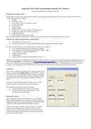
SERVO and ESC programming and testing (continued)Function Screen/Mode Cables/Wiring8.5 Servo Testing by Profile MAIN>SERVO TESTER Servo and 4.8~6.0V Rx batteryCreation of a test profile. A test profile consists of a series of records, each containing a signal pulse width in microsecs and adelay time in milliseconds. This tells the servo to what position it should move and for how long it should stay there.The profile itself can be created on a Personal Computer as a simple text file, but must have a .dat extension and must sit in thedata directory on the SD card when in use on <strong>Emeter</strong>. A header record is followed by any number of details, for example:PW-uS, DELAY-mS00911, 0010001000, 00100Alternatively, create the profile directly on the <strong>Emeter</strong> II as follows:From the SERVO TESTER screen, move to the OPEN PROFILE screen by pressing ’B’ Load, and then to the NEW PROFILE by ‘B’,New. This screen allows you to specify the Pulse Widths and Delay Times by turning the pot. They will then be given a uniquenumber and stored on the SD card for future use. The Profile files may be renamed to a more meaningful name up to 8 charactersin length on the PC.Use of existing profile. When on the SERVO TESTER screen press ‘B’ (Load) to display all known test Profiles. Press ‘D’ to browsethrough the list and ‘C’ (go) to pick.Two parameters can be set by pressing ‘C’ Mode. The ‘Repeats’ parameter determines whether the test profile is to be executedcontinuously or once only, and the second controls data logging. Press ‘C’ to step through the four permutations for the one whichyou want. The defaults are Repeats ‘yes’ and ‘logging no’. You now have the option to start the servo test by pressing ‘D’ (start)Deletion of unwanted profile. PROFILE_TEST screen after picking profile, press ‘B’ delete and ‘D’ to confirm deletion.8.6 ESC Driver - Automatic MAIN>SERVO TESTER Servo and Rx batteryThis is identical to the above servo testing from a profile, except that the ESC replaces the servo. It is not possible to run theANALYSER screen at the same time as PROFILE TEST, however from the latter, it is possible to control data logging by pressing ‘C’Once logging has started, press ‘D’ to start running the test profile. Press ‘C’ again to stop logging. The results can subsequently beplayed back on the Log Files screens.We strongly recommend that any test profile which is to be used for driving an ESC and a motor should have the firstfew seconds in the profile set to a motor-off signal such as 950 uS. If, during a profile controlled ESC motor test, there is anurgent need to terminate the run quickly, then it is only necessary to press ‘D’ Stop. This will cause processing to go back to thefirst data record in the profile test file (which corresponds to motor off) and to wait there for the next action by the user8.7 Servo/ESC Driver Manual From any screen at any time ESC (opto esc require 4.8-6v Rx battery)Connect <strong>Emeter</strong> II, Rx battery and servo or ESC as for Servo Cycle Testing, but exit from the cycle testing screen.Rx battery MUST BE LEFT OUT if the ESC has BEC circuitry, UNLESS the +ve wire to the ESC is disconnectedSet the <strong>Emeter</strong> II pot. to the throttle closed position - fully anticlockwise (Futaba may need clockwise). For model aircraft, initiallytest for correct wiring and functioning with no propeller, as a safety precaution.Turn pot. to drive servo. Note, the servo driver is opto-isolated and may be used independently of, or combined with, any other<strong>Emeter</strong> II functions. See diagram at end of this document for more details.FIRMWARE UPGRADE and CALIBRATIONFunction Screen/Mode Cables/Wiring9.1 Calibrate volts MAIN>RDU SETUPHold ‘D’ for 3 secs. to allow access toUpgrade and Calibrate functionsRDU + RDU cablePlug RDU into power source with known voltage. Increment/decrement to match voltage. Save twice9.2 Calibrate Current (amps)Plug RDU into power source. Discharge at known current. Increment/decrement to match amps. Save twice.9.3 Upgrade <strong>Emeter</strong> IIFirmware versionBefore switch-on, press Buttons ‘A’, ‘B’, ‘C’and ‘D’ while switching power to <strong>Emeter</strong> IISD cardFirmware loader process checks for file EMFW.bin on SD card and, if found, loads the new firmware version into the <strong>Emeter</strong> II.9.4 Upgrade RDUFirmware versionMAIN>RDU SETUPHold ‘D’ for 3 secs. to allow access to RDUUpgrade functionSD card + RDU + RDU CableFirmware loader process checks for file RDUFW.bin on SD card and, if found, asks the user for confirmation before upgrade.
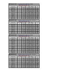
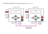
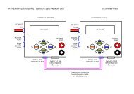
RDU SPECIFICATIONS (for RDU Type #HP-EM2-RDU)Max Input Voltage70VMax Current 5 seconds*300 AMax Current 30 seconds*150 AMax Continuous Current*75 AShunt Resistance0.0002 ΩInternal Resolution V0.001 VDisplayed Resolution V0.01 VInternal Resolution A0.04 ADisplayed Resolution A0.1 ATMP Sensor Resolution0.1 CelsiusTMP Sensor Accuracy 1%AnalogDigital Converters16 bitPhase RPM Max Readable65,000 rpmPhase RPM Resolution17 rpm (14 mag. motor)*Note that the max currents listed above are highly dependant on ambient air temperature, and especially the amount ofcooling airflow that passes through the RDU. On a cold day with good airflow, you may increase Continuous and 30-sec Maxamperages by some percentage, or reduce for hot days and poor airflow. Currents above 150A require user modification toincrease input/output wire size, and appropriate connectors. The “bottom line” is that it is your responsibility to checktemperatures to insure the RDU is not heat damaged (75C max). RDU unit returned with clear evidence of over-current heatdamage will NOT be covered by warranty replacement policy.<strong>Emeter</strong> IISimple Diagram for theBench-Test of BEC ESCand a Brushless MotorConnect to<strong>Emeter</strong> ServoDriver Port4 wire RDU to<strong>Emeter</strong> DatacableTemperaturesensorsCBABECElectronicSpeedControlTo BEC ESCMainPower PackRDURemoteDataUnitPhase TachoConnectionBrushlessMotorAlso see http://media.hyperion.hk/dn/em2 for the “<strong>Emeter</strong>II Suite” PC Software (see link at bottom of page), whichallows direct programming of RDU parameters, log file downloads from SD Card or direct from the RDU, and “live” benchtesting with RDU connected to PC. The Suite also contains graphing functions, and will soon support other features such astest profile creation for upload to the <strong>Emeter</strong>.WARRANTY- <strong>Emeter</strong> and RDU are guaranteed to be free from defects in materials and workmanship for a period of one calendar yearfrom date of purchase.- Damage due physical shock (dropping on the floor, etc), inappropriate power supply (battery charger, etc!), water,moisture, over-voltage or over-current operation, and humidity are specifically NOT covered by warranty.- Your selling dealer is your first point of contact for warranty issues.- Return postage costs are the responsibility of the user in all cases. Submit copy of original receipt with the return.- Returned units should be examined by the <strong>Hyperion</strong> dealer’s tech department within 1 week of arrival, maximum, andcontact made with the user to explain the findings.REPAIR/REPLACEMENT DUE TO NON-WARRANTY ISSUES:Due to the nature of the miniature electronics employed, and high cost of hand labor and shipping involved, it is noteconomically feasible to repair electronics in many cases. Instead, we offer a blanket exchange policy at 55% of the US$original suggested retail price (plus any taxes due in your area, and return shipping). In the event that your <strong>Emeter</strong>/RDU isuser damaged and warranty will not apply, please contact your selling dealer to obtain the correct return shipping address,for exchange under this program.Best regards from the <strong>Hyperion</strong> Team, tech@hyperion.hk