Design of a Hybrid Positioner-Fixture for Six-axis Nanopositioning ...
Design of a Hybrid Positioner-Fixture for Six-axis Nanopositioning ...
Design of a Hybrid Positioner-Fixture for Six-axis Nanopositioning ...

You also want an ePaper? Increase the reach of your titles
YUMPU automatically turns print PDFs into web optimized ePapers that Google loves.
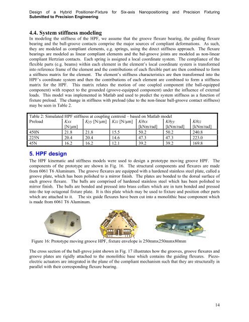
<strong>Design</strong> <strong>of</strong> a <strong>Hybrid</strong> <strong>Positioner</strong>-<strong>Fixture</strong> <strong>for</strong> <strong>Six</strong>-<strong>axis</strong> <strong>Nanopositioning</strong> and Precision FixturingSubmitted to Precision Engineering4.4. System stiffness modelingIn modeling the stiffness <strong>of</strong> the HPF, we assume that the groove flexure bearing, the guiding flexurebearing and the ball-groove contacts comprise the major sources <strong>of</strong> compliant de<strong>for</strong>mations. As such,they are modeled as compliant elements, e.g. springs, using the direct stiffness approach. The flexurebearings are modeled as linear compliant elements and the bal-groove joints are modeled as non-linearcompliant Hertzian contacts. Each spring is assigned a local coordinate system. The compliance <strong>of</strong> theflexible parts (e.g. beams) within each element in the element’s local coordinate system is trans<strong>for</strong>medinto reference frame <strong>of</strong> the element and the contributions <strong>of</strong> each flexible part are then combined to <strong>for</strong>ma stiffness matrix <strong>for</strong> the element. The element’s stiffness characteristics are then trans<strong>for</strong>med into theHPF’s coordinate system and then the contributions <strong>of</strong> each element are combined to <strong>for</strong>m a stiffnessmatrix <strong>for</strong> the HPF. This matrix relates the motion <strong>of</strong> one coupled component (the ball-equippedcomponent) with respect to the grounded (groove-equipped component) under the influence <strong>of</strong> externalloads. This model was implemented in Matlab and used to predict the system stiffness as a function <strong>of</strong>fixture preload. The change in stiffness with preload (due to the non-linear ball-groove contact stiffness)may be seen in Table 2.Table 2: Simulated HPF stiffness at coupling centroid – based on Matlab modelPreload Kxx[N/µm]Kyy [N/µm] Kzz [N/µm] Kxx[kNm/rad]Kyy[kNm/rad]Kzz[kNm/rad]450N 21.8 21.8 15.5 50.2 50.2 240.8225N 20.4 20.4 14.6 47.3 47.3 223.045N 16.2 16.2 12.1 39.2 39.2 169.85. HPF designThe HPF kinematic and stiffness models were used to design a prototype moving groove HPF. Thecomponents <strong>of</strong> the prototype are shown in Fig. 16. The structural components and flexures are madefrom 6061 T6 Aluminum. The groove flexures are equipped with a hardened stainless steel plate, called agroove plate, which has been polished to a mirror finish. The plates are bonded to the dorsal surface <strong>of</strong>each groove flexure. The balls are comprised <strong>of</strong> hardened stainless steel which has been polished tomirror finish. The balls are bonded and pressed into brass collars which are in turn bonded and pressedinto the top octagonal fixture plate. It is this plate which may be used to fixture and position other partswhich are attached to it. The six guide flexures have been cut into a monolithic base component whichis made from 6061 T6 Aluminum.Figure 16: Prototype moving groove HPF, fixture envelope is 250mmx250mmx80mmThe cross section <strong>of</strong> the ball-grove joint shown in Fig. 17 illustrates how the grooves, groove flexures andgroove plates are rigidly attached to the monolithic base which contains the guiding flexures. Piezoelectricactuators are integrated in the plane <strong>of</strong> the compliant mechanism such that they are structurally inparallel with their corresponding flexure bearing.14