Design of a Hybrid Positioner-Fixture for Six-axis Nanopositioning ...
Design of a Hybrid Positioner-Fixture for Six-axis Nanopositioning ...
Design of a Hybrid Positioner-Fixture for Six-axis Nanopositioning ...

You also want an ePaper? Increase the reach of your titles
YUMPU automatically turns print PDFs into web optimized ePapers that Google loves.
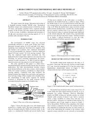
<strong>Design</strong> <strong>of</strong> a <strong>Hybrid</strong> <strong>Positioner</strong>-<strong>Fixture</strong> <strong>for</strong> <strong>Six</strong>-<strong>axis</strong> <strong>Nanopositioning</strong> and Precision FixturingSubmitted to Precision Engineeringgroove interface to reduce settling time <strong>of</strong> the fixture. The setup was placed on an air table and allowedto come to thermal equilibrium within an insulated enclosure. The uncertainty in the measurement systemvaried <strong>for</strong> the type <strong>of</strong> test run, these numbers are reported separately <strong>for</strong> each test.BaseGrooveflexuresDecouplingflexureFigure 19: Test stand used to characterize HPF per<strong>for</strong>mancePalletBall6.2. Positioning: Open-loop per<strong>for</strong>mance in a non-calibrated stateDisplacement tests were run to characterize the fixture’s ability to provide pure displacement in each <strong>axis</strong>.The tests were run prior to calibration and without feedback control. Five positions were measured pertest, one at the home position and two on either side <strong>of</strong> home. Between each position measurement, thepreload was removed, the grooves were actuated to the desired position and then the preload wasreapplied. The control/data acquisition was programmed to permit the fixture to settle <strong>for</strong> 30 seconds.Ten readings at each position were taken, and then averaged to obtain the final data point. Theuncertainty <strong>of</strong> the measurements in this experiment was 60 nm. The displacements and parasitic errorsmeasured in each test are provided in Fig. 20 and Fig. 21. The dotted line in the figures has a slope <strong>of</strong>unity and pierces the origin. If no errors are present between commanded and measured displacement, thedata points should lie on this line.16