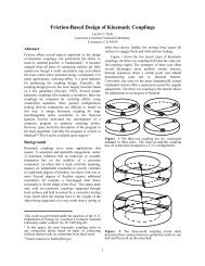
<strong>Design</strong> <strong>of</strong> a <strong>Hybrid</strong> <strong>Positioner</strong>-<strong>Fixture</strong> <strong>for</strong> <strong>Six</strong>-<strong>axis</strong> <strong>Nanopositioning</strong> and Precision FixturingSubmitted to Precision EngineeringMeasured [radians]Measured [radians]Measured [radians]5002500-250-500500250x displacement-500 -250 0 250 500Command [radians]0-250-5005002500-250-500y displacement-500 -250 0 250 500Command [radians]z displacement-500 -250 0 250 500Command [radians]Error [m]Error [m]Error [m]1050-5-1010-5-10x - Parasitic errorsxyzTheta yTheta z-500 -250 0 250 500Command [microns]50y - Parasitic errors-500 -250 0 250 500Command [microns]1050-5-10xyzTheta xTheta zz - Parasitic errorsxyzTheta xTheta y-500 -250 0 250 500Command [microns]Figure 21: Orientation tests results which compare the measured vs. commanded HPF behavior (left)and the parasitic errors as a function <strong>of</strong> commanded behavior (right)Several linear relationships between the commanded displacement and the parasitic errors may bee seenwithin the parasitic error plots. Some <strong>of</strong> these relationships are denoted on the right sides <strong>of</strong> Figs. 20 and21 by line fits. The linear relationship between command and error is important as it shows thesesystematic errors are well-correlated to the actuation inputs. This opens the door to an elegant calibrationtechnique which will be described later in this section. The systematic errors are in-part due to:020100-10-202010-10-2020100-10-20Error [radian]Error [radian]Error [radian]18
<strong>Design</strong> <strong>of</strong> a <strong>Hybrid</strong> <strong>Positioner</strong>-<strong>Fixture</strong> <strong>for</strong> <strong>Six</strong>-<strong>axis</strong> <strong>Nanopositioning</strong> and Precision FixturingSubmitted to Precision Engineering(1) Geometry errors: The physical components which define the HPFs kinematic chains differ from theideal components which drive the kinematic model. For example there are errors in the reference andaligning features <strong>of</strong> each component which affect the assembly <strong>of</strong> each component. There are also errorsin the size <strong>of</strong> the components which define the HPFs kinematic chains, repeatable parasitic errors in theguide flexures which are due to imperfect geometry <strong>of</strong> the compliant parts, and actuator misalignmenterrors.(2) Material property errors: The model assumes isotropic material properties <strong>for</strong> Aluminum and aYoung’s Modulus <strong>of</strong> 30 ksi Young’s Modulus. It is not uncommon <strong>for</strong> the modulus <strong>of</strong> Aluminum alloyswhich have been <strong>for</strong>med into sheet to differ by 5-10% fro the generic 30ksi value.6.3. Removing systematic errors via calibrationThe calibrated position and orientation vector, PO C , may be related to the model’s predicted position andorientation vector, PO M , via the calibration matrix, C, given in Eqxn. 29. In this approach, we arecalibrating the HPF by modifying the model rather than modifying the hardware.POCXcYcZc C PO MxcyczcCalibratedC11C21C31C41C51C61C12C22C32C42C52C62C13C23C33C43C53C63C14C24C34C44C54C64C15C25C35C45C55C65C16C26C36C46C56C66XcYcZcxcyczcModelThe rows <strong>of</strong> the matrix may be populated using the results <strong>of</strong> the single-<strong>axis</strong> tests. For instance, during anX <strong>axis</strong> move, PO M , would be [Xc, 0, 0, 0, 0, 0] T and the pre-calibrated, experimentally determinedposition and orientation vector, PO E , would be given by Eqxn 30.(29)XcYcZcxcycFor POMzcExperimental [ Xc,0,0,0,0,0]TC Xc11C Xc21C Xc31C Xc41C Xc51C Xc61The slope <strong>of</strong> the lines which were fitted to the data plotted in Figs. 20 and 21 may be used as theconstants, C i1 , <strong>for</strong> the first column <strong>of</strong> the calibration matrix. The same procedure may be used to populatethe 2 nd , 3 rd , 4 th , 5 th , and 6 th , columns using the Yc, Zc, xc, yc, and zc tests respectively. Thecompleted matrix <strong>for</strong> the moving groove HPF prototype is provided in Eqxn. 31.(30)19