Design of a Hybrid Positioner-Fixture for Six-axis Nanopositioning ...
Design of a Hybrid Positioner-Fixture for Six-axis Nanopositioning ...
Design of a Hybrid Positioner-Fixture for Six-axis Nanopositioning ...

You also want an ePaper? Increase the reach of your titles
YUMPU automatically turns print PDFs into web optimized ePapers that Google loves.
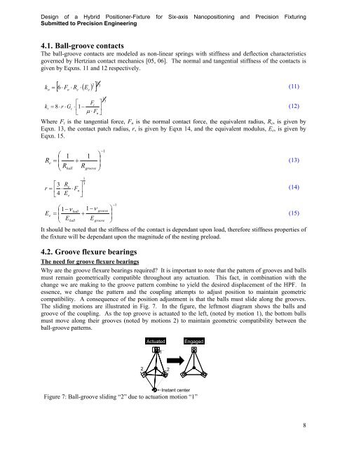
<strong>Design</strong> <strong>of</strong> a <strong>Hybrid</strong> <strong>Positioner</strong>-<strong>Fixture</strong> <strong>for</strong> <strong>Six</strong>-<strong>axis</strong> <strong>Nanopositioning</strong> and Precision FixturingSubmitted to Precision Engineering4.1. Ball-groove contactsThe ball-groove contacts are modeled as non-linear springs with stiffness and deflection characteristicsgoverned by Hertzian contact mechanics [05, 06]. The normal and tangential stiffness <strong>of</strong> the contacts isgiven by Eqxns. 11 and 12 respectively.kn12 F R E 3 (11)6n e e F tkt 8r Gc 1 Fn13Where F t is the tangential <strong>for</strong>ce, F n is the normal contact <strong>for</strong>ce, the equivalent radius, R e , is given byEqxn. 13, the contact patch radius, r, is given by Eqxn 14, and the equivalent modulus, E e , is given byEqxn. 15.(12)1R 1 1 e RballR(13)groove 133R er Fn(14)4EeEe1 Eballball1Egroovegroove1It should be noted that the stiffness <strong>of</strong> the contact is dependant upon load, there<strong>for</strong>e stiffness properties <strong>of</strong>the fixture will be dependant upon the magnitude <strong>of</strong> the nesting preload.4.2. Groove flexure bearingsThe need <strong>for</strong> groove flexure bearingsWhy are the groove flexure bearings required? It is important to note that the pattern <strong>of</strong> grooves and ballsmust remain geometrically compatible throughout any actuation. This fact, in combination with thechange we are making to the groove pattern combine to yield the desired displacement <strong>of</strong> the HPF. Inessence, we change the pattern and the coupling attempts to adjust position to maintain geometriccompatibility. A consequence <strong>of</strong> the position adjustment is that the balls must slide along the grooves.The sliding motions are illustrated in Fig. 7. In the figure, the leftmost diagram shows the balls andgroove <strong>of</strong> the coupling. As the top groove is actuated to the left, (noted by motion 1), the bottom ballsmust move along their grooves (noted by motions 2) to maintain geometric compatibility between theball-groove patterns.(15)ActuatedEngaged12 2Instant centerFigure 7: Ball-groove sliding “2” due to actuation motion “1”8