

Specification sheet - Trend
Specification sheet - Trend
Specification sheet - Trend
- No tags were found...

Create successful ePaper yourself
Turn your PDF publications into a flip-book with our unique Google optimized e-Paper software.
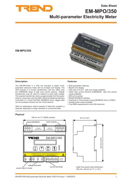
Data SheetEM-MPO/350Multi-parameter Electricity MeterEM-MPO/350DescriptionThe EM-MPO/350 is a DIN rail mounted 3 phase multiparameterelectricity meter with an (8 digit) LCD display. The/350 requires 5 A current transformers, and the /350e usesthe CSENSOR range of split core current sensors. Voltagetransformers may be used for medium to extra high voltage.The required transformer ratio is programmable from the panel.Used in conjunction with the EMIC (Ethernet Metering InterfaceController) or a <strong>Trend</strong> IQ3/XNC MODBUS driver, logged datacan be accessed directly over the <strong>Trend</strong> network.Ideal for applications where analysis of electricity supplies isrequired, especially on large industrial or commercial sites.Features▪▪Multi-parameter metering▪▪Backlit LCD display▪ ▪/350 uses CTs (CT/.. split core range available)▪ ▪/350e uses current sensors (CSENSOR/.. split core sensorrange available)▪▪DIN rail mounting▪▪RS485 MODBUS interface▪▪Interfaces to <strong>Trend</strong> system (using MODBUS driver or EMIC)▪▪Isolated pulse output available▪▪True RMS measurement to the 30th harmonicPhysical106 mm (4.17”) (6DIN module)58 mm (2.28”)Serial MODBUSpulse outputs15 16 17 29 30 31 32A B 0VIsolatedSerial CommsIsolatedPulse outputsPls2 Pls1EM-MPO/35090 mm (3.54”)CURRENT INPUTS - DO NOT USE STANDARD CTsuse only special 0.33V ac output transducers- + Vn V1 V2 V3 +l1- +l2- +l3-1 2 3 4 5 6 7 8 9 10 11 12CurrentInputsvoltage terminalspower input to metercurrent terminalsmeter front panel cutout dimension:106 mm x 46 mm (4.17” x 1.81”)EM-MPO/350 Multi-parameter Electricity Meter TA201105 Issue 1, 16/08/20101
10040 V1 2 3 4 5 61 2+ 0 + 07 8 9 10 11 123 + 0 4 + 010040 V1 2 3 4 5 61 2+ 0 + 07 8 9 10 11 123 + 0 4 + 013 14 15 16 17 18 19 20 21 22 23 24 25 26 27 28 29 305 67 89 10+ 0 + 0 + 0 + 0 + 0 + 0A 11 12 13 14 15 16P 0 P 0 P 0 P 0 P 0 P 0OK RXP 31 32 33 34 35 36 37 38 39 40 41 42 43 44 45 46 47 4824 V0 V24 V13 14 15 16 17 18 19 20 21 22 23 24 25 26 27 28 29 305 67 89 10+ 0 + 0 + 0 + 0 + 0 + 0RS48524 V0 V24 VTXRXRTS/TXENCTS/RXENRS232A 11 12 13 14 15 16P 0 P 0 P 0 P 0 P 0 P 0OK RXP 31 32 33 34 35 36 37 38 39 40 41 42 43 44 45 46 47 48EM-MPO/350Data SheetFunctionalitySYSTEMThe EM-MPO/350 can be connected to the <strong>Trend</strong> system using either the EMIC, or the IQ3../XNC/SER (with the MODBUS driverinstalled). Either the EMIC or the MODBUS driver is able to access the EM-MPO/350 and read its values and set up its parameters.EMICThe EMIC can connect to a maximum of between 8 and 32 metersdepending on its version.The adjacent diagram shows the physical connections. TheSupervisor, IQ3 controller, EINC, and EMIC are connected tothe Ethernet bus. The EMIC is connected to its meters using theMODBUS (RS485).SupervisorIQ3 ControllerEthernetThe EM-MPO meter takes the measurements and these are readby the EMIC using standard RS485 MODBUS protocol. The EMICstores this data in memory and calculates further measurements.<strong>Trend</strong> system devices can then read the measurements from theEMIC using <strong>Trend</strong> network communications.EINCEMICMODBUS (RS485)Meter 1Meter nSupervisorEINCEMICvOSvOS vIQMeter 1vOSvCNCLanINCInternetworkINC(126)LanvOSsupervisor modealarm modevCNCvCNCINCvOSvOSvOSMeter nvCNCIQ3ControllerThe EMIC is a member of the internetwork, and its firmware simulates a Lan with each meter represented as a virtual outstation (e.g.a virtual IQ Controller). A supervisor (e.g 963) can connect to the EMIC by way of a vCNC (virtual Comunications Node Controller)in an EINC (or 3xtend/EINC L, or IQ3).In the above diagram, the Supervisor connects to the EINC’s Lan using a supervisor mode vCNC. The INCs, Internetwork NodeControllers (EINC’s, EMIC’s, and IQ3’s) construct an internetwork. The supervisor can communicate across the internetwork toobtain the meter readings from a vOS (virtual outstation). A vOS can send Sensor High and Low alarms to the supervisor eitherthrough the EINC’s vCNC in supervisor mode if the supervisor is permanently connected or through a EINC vCNC set to alarmmode if the supervisor is not permanently connected.The IQ3 controller is able to send Inter-Contoller Communications to the EMIC (e.g. to obtain meter readings). The IC Commscannot be attribute comms so are limited to simple Data To and Data From comms.IQ3/XNC MODBUS DriverIQ3/XNC MODBUS Driver is a TCL application for <strong>Trend</strong>’sIQ3/XNC. Once configured, it enables values from devices onMODBUS to be read into the strategy of an IQ3/XNC. It alsoenables values from the strategy to be written to values in theMODBUS device. The driver interrogates meters of differenttypes using their MODBUS addresses and reads/writes from/toa specified location in the device. Data read from the device isstored in the IQ3/XNC’s TCL Interface module’s outputs. Theseobjects can then be used in the IQ3/XNC’s strategy. Data thatis to be written to the device is taken from the IQ3/XNC’s TCLInterface module’s inputs. These inputs can be modified fromthe IQ3/XNC’s strategy.EthernetSupervisorIQ3 ControllerMODBUS (RS485)Meter 1Meter nThe IQ3/XNC MODBUS Serial Driver is available in two different sizes (35 data requests, 20 inputs with 85 outputs and 185 datarequests, 150 inputs with 400 outputs), and should be downloaded into an IQ3/XNC/SER for use with EM-MPO/350.The driver can be downloaded from the <strong>Trend</strong> Partnernet website, and copied into a SET (System Engineering Tool) project. It canthen be configured (see IQ3/XNC MODBUS Driver Manual TE201101) to define the parameters from each meter that are to becommunicated, and the file can then be downloaded to the IQ3/XNC as part of the strategy download.2 EM-MPO/350 Multi-parameter Electricity Meter TA201105 Issue 1, 16/08/2010
EM-MPO/350Data SheetCurrent SensorsThe EM-MPO350 uses the CT range of split core currenttransformers, whereas the EM-MPO/350e uses the CSENSORsplit core current sensors.A CSENSOR has an internal precision resistor connectedacross the secondary winding providing a safe low voltageoutput (0.333 Vac at CSENSOR nominal current). Due to theirlow voltage output CSENSORs have the advantage that theoutputs can left open circuit if not connected to a meter (unlikea CT which must be short circuited). The outputs from thesesensors must be wired individually direct to the meter and mustnot be earthed or connected to any other circuit.FirmwareParametersThe table below lists al the parameters avalable from the meter.Most parameters are available over the MODBUS interface,those available on the front panel are indicated.ParameterFront PanelButton DisplayNotesPhase 1 Current Current P1 APhase 2 CurrentP2 APhase 3 CurrentP3 APhase 1 Voltage Voltage P1 VPhase 2 VoltageP2 VPhase 3 VoltageP3 VLine 1 Voltage L1 V Line 1 toLine 2Line 1 Voltage L2 V Line 2 toLine 3Line 1 Voltage L3 V Line 3 toLine 1System Active Power Power kWSystem Power Factor PF Note 1Frequency HzF(Phase 1 voltage)Phase 1 Active PowerP1 kWPhase 2 Active PowerP2 kWPhase 3 Active PowerP3 kWPhase 1 Power Factor PF 1 Note 1Phase 2 Power Factor PF 2 Note 1Phase 3 Power Factor PF 3 Note 1Active Energy Register Energy kWhHours RunrhReactive Energy Register kVArh ImportkVArhNeutral Current ASystem kVASystem kVArSystem kVAhkVArh InductivekVArh capacitativeExport kVArhExport KWhPhase 1 kVAPhase 2 kVAPhase 3 kVAPhase 1 kVArPhase 2 kVArPhase 3 kVArNote 1: If the power factor is capacitive, the Display has suffix‘c’ (e.g. PFc). If the power factor is inductive there is no suffix(e.g. PF).Only available using MODBUS interfaceParameterPeak Hold Phase 1 APeak Hold Phase 2 APeak Hold Phase 3 APeak Hold Phase 1 VPeak Hold Phase 2 VPeak Hold Phase 3 VPeak Hold kW DemandkW Demand PeriodkW DemandkVA DemandPeak Hold kVA DemandkVAr DemandPeak Hold kVAr DemandPeak Ph1 Amps DemandPeak Ph2 Amps DemandPeak Ph3 Amps DemandPeak Ph1 Volts DemandPeak Ph2 Volts DemandPeak Ph3 Volts DemandPh1 Amps DemandPh2 Amps DemandPh3 Amps DemandPh1 Volts DemandPh2 Volts DemandPh3 Volts DemandV1% THDV2% THDV3% THDI1% THDI2% THDI3% THDkW DemandkVA DemandkVArh DemandPeak Hold kW DemandPeak Hold kVA DemandPeak Hold kVAr DemandV1: 2nd to 15thHarmonicsV2: 2nd to 15thHarmonicsV3: 2nd to 15thHarmonicsFront PanelButton DisplayOnly available using MODBUS interfaceNotes14parameters14parameters14parametersI1: 2nd to 15th Harmonics 14parametersI2: 2nd to 15th Harmonics 14parametersI3: 2nd to 15th Harmonics 14parametersCT primary Program Ct A ANominal Volts Un V See Note 2Pulse 1 RatePLrkWhNote 3Pulse 2 Rate(=pulse 1 rate)PLrkWhNote 3Pulse ON time PLt Note 3Hours Run Limit Hr kWBaudBrModbus AddressAddrCurrent Demand Period Only available x10 secPT Scaleusing MODBUS VT scaleinterfacesee Note 24 EM-MPO/350 Multi-parameter Electricity Meter TA201105 Issue 1, 16/08/2010
Data SheetEM-MPO/350Parameters (continued)Note 2: If no VT, set Nominal Volts to 400 (meter rating - line toline voltage), and set PT Scale to 1.If VT fitted and primary volts is less than 60 kV, set NominalVolts to VT primary line to line voltage and set PT Scale to 1.If VT fitted and primary volts greater than 60 kV set NominalVolts to 6600 and set PT Scale to primary volts divided by 6600.Note 3: Note: The Pulse Rate sets the value of each pulsein kWh - pulse 1, kVArh - pulse 2 (range 1 to 1000 counts ofregister - default 0.1). The Pulse On Time is the pulse durationin secs (range 0.1 to 20 s - default 0.1).Hours RunThe Hours Run register accumulates the total time during whichthe average 3 phase load current, (I1 + I2 + I3)/3, exceeds apreset level. The limit is set on the front panel (Hours Run TripPoint - percent Amps), or in the MODBUS register ‘Hours RunLimit’. The limit is expressed as a percentage of CT PrimarycurrentSecurityA 4 digit security code can be set up from the front panel orusing the MODBUS serial communication. Once this is set upprogramming mode cannot be entered without entering thecorrect code.MODBUS CommunicationsThe MODBUS protocol is described in the EM-MPO/350 SerialCommunications Manual, TE201115.Field MaintenanceThe EM-MPO/350 requires no routine maintenance.DISPOSALProgrammingProgramming mode can be entered from the front panel. Thisenables CT primary, Nominal Volts (Pt primary), Output Pulserate, Pulse on time, Pulse Output test, Hours run trip point andauto rotation mode to be programmed. The last display ‘Storin9’ stores the changes to non-volatile memory.Fine AdjustThe CT Primary and Nominal Volts are normally selected froma table of preferred values; fine adjust mode (entered from thefront panel) enables other settings to be made. Fine adjust modeis only available on the EM-MPO/350 (not EM-MPO/350e)Pulse Output TestThe pulse output test can be run from the front panel. Thisenables the pulse output hardware and the external systemconnections to be commissioned without a measured load. Thedisplay shows Pto (off) and Ptr (run) and the number of testpulses. The test puse rate is set automatically according to theprogrammed pulse on timeCT Auto Rotation ModeWhen CT auto rotation mode is selected (default) the CTconnection polarity is ignored (the cable can be passed throughthe centre of the CT in either direction).CT auto rotation is de-selected in order to measure whetherpower is imported or exported. The CT connection polarity mustthen be correct.It is recommended to connect the CTs with correct polarity incase this parameter is changed.In the programming menu the display toggles between Auto rotand truE rot.WEEE Directive:At the end of their useful life the packaging,product, and battery (if fitted) should bedisposed of by a suitable recycling centre.Do not dispose of with normal household waste.Do not burn.COSHH (Control of Substances Hazardous to Health -UK Government Regulations 2002) ASSESSMENT FORDISPOSAL OF EM-MPO/350.RECYCLING .All plastic and metal parts are recyclable. The printed circuitboard may be sent to any PCB recovery contractor to recoversome of the components for any metals such as gold and silver.CompatibilityEMIC: The EMIC contains definition tables for both the EM-MPO/350 and the /400. These enable the major parametersto be collected from a maximum of 8, 16 or 32 meters (EMIC/MDA/8, /16, /32 respectively).<strong>Trend</strong> XNC MODBUS Driver: This enables the IQ3/XNC/SER to access a number of meters. The driver requires to beconfigured, and the controller needs additional strategy in orderto scale the values fetched from the meter.Voltage Input Mode(Recommended to be used only on EM-MPO/350e).In Balanced Voltage Mode the meter may be connected to asingle voltage source for 3 phase measurement in place of the3 phases normally required.In Balanced Voltage Mode the voltage measured on phase 1is copied to the other two phases and all three power factorsare assumed to be unity. This is valid for loads with near unitypower factor (PF=0.95 equates to an error of 5%) and balanced3 phase voltages.In the programming menu the display toggles between trUE3Ph and bAL 3Ph.EM-MPO/350 Multi-parameter Electricity Meter TA201105 Issue 1, 16/08/20105
EM-MPO/350Data SheetInstallationThe EM-MPO/350 should be mounted on a 35 mm symmetrical, ‘top-hat’, DIN rail of minimum length 106 mm. The meter conformsto DIN 43880 6 module wide which makes it compatible wth a number of standard distribution systems with 45 mm cutouts. Fullinstallation details are given in the EM-MPO/350 installation instructions, TG201107.ConnectionsMODBUSData +Data -0 V15 16 17 15 16 1715 16 17a B 0Va B 0Va B 0Va B 0Vcontroller meter meter meterterminatorFor long runs (>30 m) terminate at each endterminatorPulse Outputs100 mA ac/dc max., 100 V ac/dc max.,0.5 W max load29Pulse 2kVArhPulse 1kWh303132MonitorAMonitorB15 16 17 29 30 31 32A B 0VIsolatedSerial CommsIsolatedPulse outputsEM-MPO/350CURRENT INPUTS - DO NOT USE STANDARD CTsuse only special 0.33V ac output transducers- + Vn V1 V2 V3 +l1- +l2- +l3-1 2 3 4 5 6CurrentInputsVoltage and Current Connectionspower inputto meterpower input to meter3 phase 3 or 4 wire - Star or Delta (can use VTs)*Single phase (can use VT)*power inputto meterpower inputto meter3 phase high voltage using 2 VTs and 2 CTs* (EM-MPO/350 3 phase using 2 CTs* - Delta (EM-MPO/350 only)only)*Note that EM-MPO/350 uses current transformers (CTs), EM-MPO/350e uses current sensors (CSENSORs)6 EM-MPO/350 Multi-parameter Electricity Meter TA201105 Issue 1, 16/08/2010
Data SheetEM-MPO/350ConnectionS continuedCurrent Sensors & CTsS1 (+) redS2 (-) BlackP1P2SupplyLoadCurrentCTS2 (-) white(black/white)S1 (+) blackP1P2SupplyP1P2LoadSupplyS1 (+) BlackLoadKLCurrentKLCurrentS2 (-) White (Black/white)CSENSOR10A, 100ACSENSOR150A, 400A, 800AThe current must pass through the CT or sensor in the correct direction (the power cable passing through the CT or sensor isthe primary), and the secondary must be connected to the meter with the correct polarity (see CT Autorotation Mode above).For <strong>Trend</strong> CTs the red wire is positive and the black is negative. For CSENSORS the black wire is positive and the white (orblack/white) is negative. The CT or sensor must be connected to the same phase as its associated VT.Order CodesEM-MPO/350EM-MPO/350eCSENSOR/050CSENSOR/100CSENSOR/150CSENSOR/400CSENSOR/800:Three Phase multi-parameter meter (for use with CTs):Three Phase multi-parameter meter (for use with current sensors):Split core current sensor, 50 A nominal current for use with EM-MPO/350e, EM-MPO/400e:Split core current sensor, 100 A nominal current for use with EM-MPO/350e, EM-MPO/400e:Split core current sensor, 150 A nominal current for use with EM-MPO/350e, EM-MPO/400e:Split core current sensor, 400 A nominal current for use with EM-MPO/350e, EM-MPO/400e:Split core current sensor, 800 A nominal current for use with EM-MPO/350e, EM-MPO/400eCurrent transformersCurrent transformers (CTs) should be ordered separately. A range of split core CTs are available from <strong>Trend</strong> as described in the CurrentTransformers data <strong>sheet</strong> TA102139.EM-MPO/350 Multi-parameter Electricity Meter TA201105 Issue 1, 16/08/20107
EM-MPO/350Data Sheet<strong>Specification</strong>ElectricalMeter Power Input Voltage :230 Vac 50/60 Hz ±15 %Meter Power Input Consumption:5 W max.Meter Power Input Overload :Nominal x1.2 continuousMetered Voltage :Nominal - 230 Vac phase to neutral, 400Vac phase to phase (45 to 65 Hz).Overload Voltage :4 x nominal voltage for 1 hourVoltage Burden :


