

Installation/mounting instruction - Trend
Installation/mounting instruction - Trend
Installation/mounting instruction - Trend

Create successful ePaper yourself
Turn your PDF publications into a flip-book with our unique Google optimized e-Paper software.
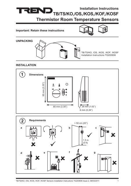
<strong>Installation</strong> InstructionsTB/TS/KO, /OS, /KOS, /KOF, /KOSFThermistor Room Temperature SensorsImportant: Retain these <strong>instruction</strong>sunpackingTB/TS/KO, /OS, /KOS, /KOF, /KOSF<strong>Installation</strong> Instructions TG200606<strong>Installation</strong>1Dimensions85 mm (3.35”)85 mm (3.35”) 26 mm (1.02”)6 mm (0.24”)2aRequirementsb> 50 cm (20”)c1.5 m(5 ft)d ef gTB/TS/KO, /OS, /KOS, /KOF, /KOSF Sensors <strong>Installation</strong> Instructions TG200606 Issue 2, 08/03/2011 1
TB/TS/KO, /OS, /KOS, /KOF, /KOSF<strong>Installation</strong> Instructions<strong>Installation</strong> (continued)2Requirements (continued)hij-10 °C(14 °F)+50 °C(122 °F)0 °C(32 °F)+40 °C measurment(104 °F)0 0 %RH 90 %RHkla3Remove backplateb4BESA boxMount backplate35 mm (1.38”)35 mm (1.38”)wall box60 mm (2.36”)or wallFRABS35 mm (1.38”)35 mm (1.38”)Remove Cutout(s)Route cables5 as required62 TB/TS/KO, /OS, /KOS, /KOF, /KOSF Sensors <strong>Installation</strong> Instructions TG200606 Issue 2, 08/03/2011
<strong>Installation</strong> InstructionsTB/TS/KO, /OS, /KOS, /KOF, /KOSF<strong>Installation</strong> (continued)7Wire to controllerTerminal size 0.5 to 2.5 mm 2(14 to 20 AWG)1 2 3 4 5 6Note that these options (TB/TS/KO,/OS, /KOF, /KOSF) cannot be usedwith IQLs; use options TB/TS,TB/TS/K, /KE, or /KEF with IQLs.SENSOR1TB/TS2/K, /O/S/F34560 VTemperatureKnobStatus/Power+24 VFanIQCOM (0V)analogue inputINlinked for thermistor (T)IN analogue inputlinked for thermistor (T)COM (0 V)OUT analogue outputlinked for voltage (V)0 V see note ** below+24 V auxiliary supplyIN analogue inputlinked for voltage (V)COM (0 V)5 - 5 4 13! 8 8 6 *65 6 A F A = H JK HA E "8 5.!"# >5 J= JK I2 MA H " 8 8 E "8 2 K J 8 8" 8)= = C EF K JJD A HEIJ H6= = C EF K JJD A HEIJ H6= = C K FJK JL J= C ALI A A JA> AM= K NEE=HOI K F FOOPTIONCONNECTTERMINALSTB/TS 1, 2TB/TS/K 1, 2, 3TB/TS/KO*** 1, 2, 3, 4*TB/TS/OS*** 1, 2, 3**, 4TB/TS/KOS*** 1, 2, 3, 4TB/TS/KOF*** 1, 2, 3, 4*, 5, 6TB/TS/KOSF*** 1, 2, 3, 4, 5, 6$. =8 8 = = C EF K J E L J= C A8 "8 Assemble unit* For /KO or /KOF connect Status/Power to 10 Vdc or24 Vdc; if using /KOS, /OS, /KOSF as /KO or /KOF, theStatus/Power input should be powered from 10 Vdc e.g.via dummy analogue output.** For /OS option also connect knob (the knob input willsupply the override circuit).*** Note that /KO, /OS, /KOS, /KOF, /KOSF cannot beused by IQ211 (although they can be used by IQ212)‘click’9Set up special IQ strategies13orFor /KO, /OS, /KOS, /KOF, /KOSF specialoverride and status strategies.For /KOF, /KOSF special strategy for fan speedinput on IQs13IQ Configuration Manual 90-1533IQ3 Configuration ManualTE200768TB/TS Data Sheet TA200603VoltageLegend Switch positionNominal RecommendedFan Off0VFan low speed 2.8V >2 VFan medium speed 5.6V >4.5 VFan high speed 8.5V >7 VAutomatic 9.7V >9 VNote that the IQ recommended limits may need to be changed to suit mains supply voltage andauxiliary supply loading, or a 24 Vdc regulated supply can be used.TB/TS/KO, /OS, /KOS, /KOF, /KOSF Sensors <strong>Installation</strong> Instructions TG200606 Issue 2, 08/03/2011 3


