


You also want an ePaper? Increase the reach of your titles
YUMPU automatically turns print PDFs into web optimized ePapers that Google loves.
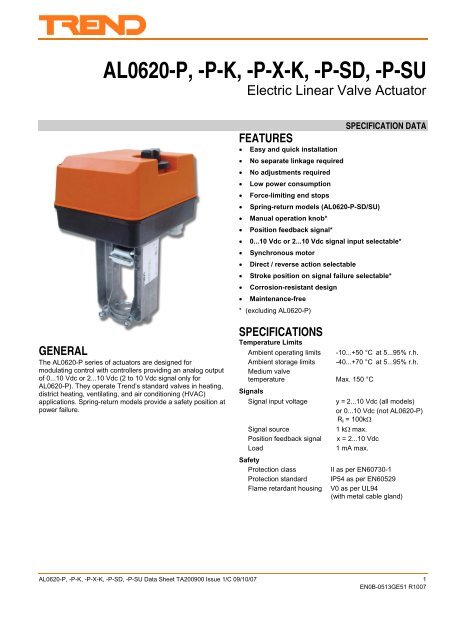
<strong>AL0620</strong>-P, -P-K, -P-X-K, -P-SD, -P-SUElectric Linear Valve ActuatorSPECIFICATION DATAFEATURES• Easy and quick installation• No separate linkage required• No adjustments required• Low power consumption• Force-limiting end stops• Spring-return models (<strong>AL0620</strong>-P-SD/SU)• Manual operation knob*• Position feedback signal*• 0...10 Vdc or 2...10 Vdc signal input selectable*• Synchronous motor• Direct / reverse action selectable• Stroke position on signal failure selectable*• Corrosion-resistant design• Maintenance-free* (excluding <strong>AL0620</strong>-P)GENERALThe <strong>AL0620</strong>-P series of actuators are designed formodulating control with controllers providing an analog outputof 0...10 Vdc or 2...10 Vdc (2 to 10 Vdc signal only for<strong>AL0620</strong>-P). They operate <strong>Trend</strong>’s standard valves in heating,district heating, ventilating, and air conditioning (HVAC)applications. Spring-return models provide a safety position atpower failure.SPECIFICATIONSTemperature LimitsAmbient operating limits -10...+50 °C at 5...95% r.h.Ambient storage limits -40...+70 °C at 5...95% r.h.Medium valvetemperature Max. 150 °CSignalsSignal input voltage y = 2...10 Vdc (all models)or 0...10 Vdc (not <strong>AL0620</strong>-P)R i = 100kΩSignal source1 kΩ max.Position feedback signal x = 2...10 VdcLoad1 mA max.SafetyProtection classII as per EN60730-1Protection standard IP54 as per EN60529Flame retardant housing V0 as per UL94(with metal cable gland)<strong>AL0620</strong>-P, -P-K, -P-X-K, -P-SD, -P-SU Data Sheet TA200900 Issue 1/C 09/10/07 1EN0B-0513GE51 R1007
<strong>AL0620</strong>-P, -P-K, -P-X-K, -P-SD, -P-SUWiringWiring terminals 1.5 mm 2Cable entryM20 cable gland and twoadditional knockouts PG11 andPG13.5 forauxiliary switch accessory.Knock-outs only for <strong>AL0620</strong>-PWeightnon-spring return typespring return typeMaterialCoverBaseYokeData Sheet1.3 kg2.4 kgABS-FRglass fiber reinforced plasticaluminum diecastmodel number <strong>AL0620</strong>-P <strong>AL0620</strong>-P-K <strong>AL0620</strong>-P-X-K <strong>AL0620</strong>-P-SD <strong>AL0620</strong>-P-SUsupply voltage24 Vac ±15%; 50/60 Hzpower consumption 5 VA 7 VA 11 VAsignal input 0(2) Vdc Actuator stem retracted. Two-way valve:”open”, Three-way valve port A-AB:”closed” *signal input 10 Vdc Actuator stem extended. Two-way valve:”closed”, Three-way valve port A-AB:”open” *stroke20 mmrun time at 50 Hz 1 min 0.5 min 1.8 minclose-off force≥ 600 Nspring return time ⎯ ≈12 sspring return direction⎯actuator stem extendsat power failure* Factory setting; can be reversed (except for <strong>AL0620</strong>-P) by action selector plug W3.actuator stem retractsat power failureOPERATIONGeneralThe drive of a synchronous motor is converted into linearmotion of the actuator stem via a spur gear transmission. Theactuator stem is connected with the valve stem by a buttonkeyedretainer connection.An integrated spring package limits the stem force to afactory-set value in either direction.Installed microswitches switch off the actuator precisely whenthe specified stem force is reached.Manual Operation (not available on <strong>AL0620</strong>-P)Actuators without spring return are equipped with a manualoperation knob used in case of power failure. Manualoperation is permitted only after the power supply is switchedoff or disconnected.To operate, push the manual operation knob down and turnclockwise to move the stem downward and counterclockwiseto move the stem upward. If the actuator returns to automaticcontrol, the manual operation knob unlocks automatically.In the case of actuators with spring return, the manualoperation knob is located under the cover.Spring ReturnThe <strong>AL0620</strong>-P-SD/SU spring return actuators provide adefined safety position of the valve in case of power failure.The spring return actuators are shipped from the factory witha shipment stop (to lock the manual operation knob) in orderto allow connection of the stem button retainer to the valvestem without power supply.Electrical InstallationThe actuators (except for <strong>AL0620</strong>-P) are delivered with a preinstalledcable gland M20 x 1.5 (with strain relief) and twoadditional knock-outs for PG11 and PG13.5.<strong>AL0620</strong>-P has 3 knockouts, 2 x PG13.5 and 1 x PG11.Max. cable length/diameter for field mounting:200 m / 1.5 mm 2 or100 m / 1.5 mm 2 (<strong>AL0620</strong>-P-X-K)NOTE: To avoid malfunction, it is necessary to connect24 Vac power and ground (see wiring section onpage 4).Input Signal Failure (not available on <strong>AL0620</strong>-P)By means of selector plug W1* the actuator can be selectedsuch that in case of a signal input failure (e.g. a broken wire),the actuator will run to one of the three positions:0%: actuator stem position for 0(2) Vdc50%: actuator stem in central position100%: actuator stem position for 10 VdcW1 is set by the factory to 50%Input Signal Range (not available on <strong>AL0620</strong>-P)The range (0 to 10 V or 2 to 10 V) of the analog input signal Ycan be changed by changing the position of selector plug W2*2 <strong>AL0620</strong>-P, -P-K, -P-X-K, -P-SD, -P-SU x Data Sheet TA200900 Issue 1/C 09/10/07EN0B-0513GE51 R1007
Data SheetActionThe direction of action can be changed by repositioningselector plug W3*. It is set by the factory such that the stemextends at increasing signal and retracts at decreasing signal.NOTE: *Jumper plugs W1, W2 and W3 are accessibleafter the cover has been removed. They arelocated on the rear side of the protection sheetof the printed circuit board (see TG200904INTand TG200902INT).<strong>AL0620</strong>-P, -P-K, -P-X-K, -P-SD, -P-SUOutput Signal "POSITION" (not available on <strong>AL0620</strong>-P)An analog output signal 2...10 Vdc ”POSITION” is availablewhich represents the actual actuator position. It can be usedfor remote indication.When the actuator stem is extended, the output signal is10 Vdc.AccessoriesAuxiliary SwitchesThe actuators can be equipped on-site with an auxiliary switchunit with two switches. Their switching points are adjustableover the full length of the actuator stroke. The switches canbe used to switch pumps or provide remote indication of anystroke position. A cable gland M20 x 1.5 (with strain relief) isdelivered with the unit.Order Code: ACCA-AL06-SWCLOSE-OFF PRESSURE RATINGSstem force600 Nstroke20 mmvalve mm 15 20 25 32 40 50 65 80size inch ½ ¾ 1 1 ¼ 1 ½ 2 2 ½ 3valvesclose-off pressure ratings (in kPa)V162N 1600 1600 1000 700 460 260V162F 1600/1000 1000 1000 600 350 200 120 50V162X 1600 1600 1000 700 460 260V252FP 2500 2500 2500 2500 2500 2500V163N 1600 1600 1000 700 460 260V163F 1000 1000 1000 790 480 260 160 100V163X 1600 1600 1000 700 460 260For details on the valves, see following Data Sheet No.:V162N TA200890 V163F (20 mm) TA200893V162F TA200892 V162X, V163X TA200897V163N TA200891 V252FP TA200899<strong>AL0620</strong>-P, -P-K, -P-X-K, -P-SD, -P-SU Data Sheet TA200900 Issue 1/C 09/10/07 3EN0B-0513GE51 R1007
<strong>AL0620</strong>-P, -P-K, -P-X-K, -P-SD, -P-SUDIMENSIONS<strong>AL0620</strong>-P<strong>AL0620</strong>-P-K<strong>AL0620</strong>-P-X-K<strong>AL0620</strong>-P-SD<strong>AL0620</strong>-P-SU67.4135x(161)Data Sheet135x(161)67.41412422331000010014128410000100WIRING<strong>AL0620</strong> -PFig.3. Dimensions (in mm)<strong>AL0620</strong> -P-K, -P-X-K (0/2...10 V)POS<strong>AL0620</strong>-P-SD/SU (0/2...10 V)POSY2...10 VY0(2*)...10 V2...10 VY0(2*)...10 V2...10 VM24 V24 V~24 V24 V~M24 V24 V~1override24 V24 V~M24 V24 V~1override24 V24 V~22BAccessoryACCA-AL06-SWDISPOSALWEEE Directive:1 2 3 4 5 6S1 S2auxiliary switchesmaximum rating: 230 Vac5 A resistive3 A inductiveAt the end of their useful life the packagingand product should be disposed of by a suitablerecycling centre.Do not dispose of with normal household waste.Do not burn.Manufactured for and on behalf of the Environmental and Combustion Controls Division of Honeywell Technologies Sàrl, Ecublens, Route du Bois 37,Switzerland by its Authorized Representative.©<strong>Trend</strong> Control Systems Limited 2007. <strong>Trend</strong> Control Systems Ltd reserves the right to revise this publication from time to timeand make changes to the content hereof without obligation to notify any person of such revisions or changes.<strong>Trend</strong> Control Systems LimitedP.O. Box 34 Horsham, West Sussex, RH12 2YF, UK. Tel: +44 (0)1403 211888, Fax: +44 (0)1403 241608, www.trend-controls.com4 <strong>AL0620</strong>-P, -P-K, -P-X-K, -P-SD, -P-SU Data Sheet TA200900 Issue 1/C 09/10/07EN0B-0513GE51 R1007


