FlexPak 3000 Digital DC Drive Hardware ... - Reliance Electric
FlexPak 3000 Digital DC Drive Hardware ... - Reliance Electric
FlexPak 3000 Digital DC Drive Hardware ... - Reliance Electric
- No tags were found...

Create successful ePaper yourself
Turn your PDF publications into a flip-book with our unique Google optimized e-Paper software.
The information in this manual is subject to change without notice.Throughout this manual, the following notes are used to alert you to safety considerations:!ATTENTION: Identifies information about practices or circumstances that can lead to personalinjury or death, property damage, or economic loss.Important: Identifies information that is critical for successful application and understanding of the product.The thick black bar shown on the outside margin of this page will be used throughout this instruction manual tosignify new or revised text or figures.!ATTENTION: Only qualified electrical personnel familiar with the construction and operation ofthis equipment and the hazards involved should install, operate, or service this equipment. Readand understand this manual in its entirety before proceeding. Failure to observe this precautioncould result in severe bodily injury or loss of life.ATTENTION: 380/415 VAC-rated <strong>FlexPak</strong> drives can be configured for either 380 VAC or 415VAC input power. Before input power is applied to the drive, verify that the control transformertaps are set to match the input power. Follow the instructions provided in chapter 3 of this manualto set the control transformer taps. Failure to observe this precaution could result in damage to,or destruction of, the equipment<strong>Reliance</strong>, <strong>FlexPak</strong>, AutoMax, and E.S.P. are trademarks of Rockwell Automation.Trademarks not belonging to Rockwell Automation are property of their respective companies.©2004 Rockwell Automation. All rights reserved.
3.6 Verify the Correct Direction of Motor Rotation ...............................................3-103.7 Determine the <strong>DC</strong> Tachometer Lead Polarity ................................................3-113.8 Make Tachometer and Armature Feedback Zero Adjustments .....................3-113.9 Make Final Adjustments.................................................................................3-12Chapter 4Chapter 5Troubleshooting/Diagnostics4.1 Check for Wiring Errors....................................................................................4-14.2 Verify AC Line and Power Input.......................................................................4-14.3 Verify <strong>DC</strong> Motor Connections...........................................................................4-24.4 Verify Optional Kits...........................................................................................4-24.5 Check the Regulator LED Status .....................................................................4-3Replacement PartsAppendix A Technical Specifications........................................................................................... A-1Appendix B Compliance with European Union Electromagnetic Compatibility Standards .......... B-1Appendix C Recommended Parts for Integrator <strong>Drive</strong>s............................................................... C-1Appendix D Glossary Of Terms ................................................................................................... D-1Index...........................................................................................................................Index-1II <strong>FlexPak</strong> <strong>3000</strong> <strong>DC</strong> <strong>Drive</strong> <strong>Hardware</strong> Reference Version 4.3
Figure 2.25 – Location of Regulator Board Terminal Strip......................................2-31Figure 3.1 – Control Transformer Locations and Settings (380/415 VAC <strong>Drive</strong>s) ....3-2Figure 3.2 – Control Transformer Settings (230/460 VAC) .......................................3-3Figure 3.3 – Regulator Board Jumpers .....................................................................3-6Figure 3.4 – AUTO REF Jumpers (J12 and J10) ......................................................3-9IV <strong>FlexPak</strong> <strong>3000</strong> <strong>DC</strong> <strong>Drive</strong> <strong>Hardware</strong> Reference Version 4.3
VI <strong>FlexPak</strong> <strong>3000</strong> <strong>DC</strong> <strong>Drive</strong> <strong>Hardware</strong> Reference Version 4.3
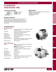
CHAPTER 1Introduction to the <strong>FlexPak</strong> <strong>3000</strong> <strong>Drive</strong>The products described in this instruction manual are manufactured by <strong>Reliance</strong><strong>Electric</strong> Industrial Company.1.1 Store the <strong>Drive</strong>After receipt inspection, repack the drive in its original shipping container until readyfor installation. To ensure satisfactory operation at startup and to maintain warrantycoverage, store the drive as follows:• In its original shipping container in a clean, dry, safe place.• In an ambient temperature that does not exceed 65°C (149°F) or go below -30°C(-22°F).• Within a relative humidity range of 5 to 95% without condensation.• Away from a corrosive atmosphere. In harsh environments, cover the shipping/storage container.• At an altitude of less than 3,000 meters (10,000 ft.) above sea level.1.2 <strong>Drive</strong> Identification NameplateThe <strong>FlexPak</strong> <strong>3000</strong> drive has a nameplate on the left side of the chassis that identifiesthe specific model number design, applicable AC input power and <strong>DC</strong> output powerdata. Refer to the sample nameplate in figure 1.1. All communication concerning thisproduct should refer to the appropriate model number information.Figure 1.1 – Sample <strong>FlexPak</strong> <strong>3000</strong> NameplatesIntroduction to the <strong>FlexPak</strong> <strong>3000</strong> <strong>Drive</strong> 1-1
1.3 Model Numbers<strong>Drive</strong> specific data, such as horsepower (or output current), regenerative or nonregenerativetype, line voltage, chassis or enclosure type, software version and ULcertification, can be determined by the drive model number. The model numberstructure is shown in figure 1.2.Up to 300 HP, drives configured for 460 VAC input can be converted to 230 VAC inputat one half the 460 VAC horsepower rating by installing a 460 to 230 Volt ConversionKit (M/N 916FK0100, 1-60 HP, or M/N 916FK0200, 75-150 HP). Instruction manualD2-3329, which is supplied with the kit, provides installation instructions. For drivesabove 300 HP, contact your local <strong>Reliance</strong> <strong>Electric</strong> sales office for assistance.For horsepower-rated drives:Horsepower under 1000For current-rated drives:Rated output armature currentF = <strong>FlexPak</strong> <strong>3000</strong> product lineB = Regenerative drives with inverting fault breakerR = Regenerative drivesN = Non-regenerative drivesK = Kits2 = 230 volts3 = 380/415 volts4 = 460 volts7 = Integrator8 = European Power Module0 = Chassis7 = IntegratorSoftware version number 0-9, A-Z0 = No listing1 = U/L and C-U/L2 = U/L, C-U/L, and CE150FR40421.4 <strong>Drive</strong> DescriptionFigure 1.2 – Model Number StructureThe drive is a full-wave power converter without back rectifier, complete with a digitalcurrent minor loop and a digital major loop for armature voltage or speed regulation bytachometer feedback. Figure 1.3 shows a block diagram of the drive.1-2 <strong>FlexPak</strong> <strong>3000</strong> <strong>DC</strong> <strong>Drive</strong> <strong>Hardware</strong> Reference Version 4.3
The drive employs a wireless construction and uses a keypad for drive setup,including parameter adjustments and unit selection, monitoring, and diagnostics.Multiple language capability in English, French, German, Spanish, Italian and‘Numeric Code' is available. Reference, feedback, and metering signals can beinterfaced to the drive. The drive can be controlled locally by the Operator InterfaceModule (OIM) keypad or remotely by using the terminals at the regulator boardterminal strip. You can select one of the following active control sources using theCONTROL SOURCE SELECT key:• KEYPAD• TERMBLK (regulator board terminal strip)• NETWORK (if an optional network communication board is installed)• SERIAL (CS<strong>3000</strong>).Figure 1.3 – <strong>FlexPak</strong> <strong>3000</strong> Functional Block Diagram1.5 Additional InformationRefer to the following publications as necessary for more information.• D2-3405 <strong>FlexPak</strong> <strong>3000</strong> <strong>DC</strong> <strong>Drive</strong>s Software Start-up and Reference Manual• D2-3344 <strong>FlexPak</strong> <strong>3000</strong> Operator Interface Module (OIM) User Guide• D2-3348 Control and Configuration Software (CS<strong>3000</strong>)• D2-3412 <strong>DC</strong> Contactor Use with Integrator <strong>Drive</strong>sIntroduction to the <strong>FlexPak</strong> <strong>3000</strong> <strong>Drive</strong> 1-3
1.6 Optional Kits<strong>Reliance</strong> offers modification kits that broaden the application range of the drive. Asummary of these kits is presented in table 1.1. Not all kits can be used with all drivemodel numbers. Refer to the Standard <strong>Drive</strong>s and Control Products catalog (D-406)for more information.Table 1.1 – <strong>Drive</strong> Modification KitsNameDescriptionModelNumberI/M Number115 VAC ControlInterface460 VAC to 230 VACConversion KitConverts customer-supplied 115 VAC signals to24 V<strong>DC</strong> for operating a <strong>FlexPak</strong> <strong>3000</strong>. Mountsseparately on the panel or can be mounted in thebottom of a NEMA 1 enclosed drive.Allows conversion of the 460 VAC <strong>FlexPak</strong> <strong>3000</strong>to a 230 VAC <strong>FlexPak</strong> <strong>3000</strong> at one-half the 460VAC horsepower rating.917FK0101 D2-3338916FK series D2-3329AC Line DisconnectKitAllows the three-phase line to be disconnected atthe drive. Molded case switch that mounts on thechassis of the drive or NEMA 1 enclosure.901FK seriesD2-3292,D2-3365 orD2-3395AC TachometerFeedback KitAutoMax NetworkCommunication BoardBlower Motor StarterKitAllows the <strong>FlexPak</strong> <strong>3000</strong> to accept feedbacksignals from AC tachometers to a maximumvoltage of 275 VAC RMS.Allows the <strong>FlexPak</strong> <strong>3000</strong> to communicate on the<strong>Reliance</strong> AutoMax Distributed Control System(<strong>DC</strong>S).Provides a fused AC starter with adjustableoverload and interlocking for control of the threephaseblower motor used to cool the <strong>DC</strong> motor.907FK0301 D2-3297915FK0101 D2-3318902FK series D2-3295DeviceNetCommunication BoardAllows a <strong>FlexPak</strong> <strong>3000</strong> to communicate over theopen protocol DeviceNet network. Mounts insidethe <strong>FlexPak</strong> <strong>3000</strong> and includes terminals fornetwork connections. You cannot use theAutoMax Network Communication board whenusing the DeviceNet board.915FK1100n/a<strong>Drive</strong> ControlConfigurationSoftware for <strong>FlexPak</strong><strong>3000</strong>ControlNet NetworkCommunicationBoardWindows-based software that allows the user toconnect any personal computer runningMicrosoft Windows version 3.1 or later to a<strong>FlexPak</strong> <strong>3000</strong> drive. Allows you to create, store,upload, and download drive configurations. Youcan also start and stop the drive, monitor andchange parameters through the PC, and readand reset the drive's fault log.Allows a <strong>FlexPak</strong> <strong>3000</strong> to communicate over theControlNet network.2CS<strong>3000</strong> D2-3348915FK2101 D2-34251-4 <strong>FlexPak</strong> <strong>3000</strong> <strong>DC</strong> <strong>Drive</strong> <strong>Hardware</strong> Reference Version 4.3
Table 1.1 – <strong>Drive</strong> Modification KitsNameDescriptionModelNumberI/M NumberDynamic Braking KitProvides the hardware, including braking grids,needed to provide dynamic braking on stop.908FK,909FK,912FK, and913FK seriesD2-3313 orD2-3374Enhanced FieldSupply KitField CurrentRegulator KitI/O Expansion BoardProvides electronic field trim, field economy, andthe ability to supply 240V field voltage and otherspecial voltages. This kit replaces the standardfield supply.Provides field economy, as well as preweakeningof the field using a fixed reference orfield weakening for above base speed operation.Tachometer feedback is required with this kit.This kit replaces the standard field supply.Mounts on the <strong>FlexPak</strong> <strong>3000</strong> chassis and givesthe <strong>FlexPak</strong> <strong>3000</strong> additional analog, frequency,and digital I/O capability.923FK series D2-3413911FK series D2-3336914FK0101 D2-3301Inverting Fault CircuitBreaker KitThis kit is an alternative to drives supplied withinverting fault fuses.906FK seriesD2-3300 orD2-3330NEMA 1 ConversionKitConverts the standard chassis to a NEMA 1enclosure.904FK seriesD2-3299 orD2-3331Operator InterfaceModule (OIM) RemoteMounting KitAllows mounting of the OIM up to five metersfrom the drive.905FK0101 D2-3294Pulse EncoderFeedback KitAllows for digital pulse encoder speed feedback. 907FK0101 D2-33021.7 Getting Assistance from <strong>Reliance</strong> <strong>Electric</strong>If you have any questions or problems with the products described in this instructionmanual, contact your local <strong>Reliance</strong> <strong>Electric</strong> sales office. For technical assistance, call864-284-5444.Introduction to the <strong>FlexPak</strong> <strong>3000</strong> <strong>Drive</strong> 1-5
1-6 <strong>FlexPak</strong> <strong>3000</strong> <strong>DC</strong> <strong>Drive</strong> <strong>Hardware</strong> Reference Version 4.3
CHAPTER 2Install and Wire the <strong>Drive</strong>2.1 Install the <strong>Drive</strong> - Panel LayoutMinimum clearances must be maintained when the drive is mounted within a cabinetas shown in figure 2.1. This allows adequate ventilation for the drive.Regardless of these placement guidelines, the user is responsible for ensuring thatthe drive's ambient temperature specification. See appendix A for more information.Install the drive(s) in the cabinet. Refer to figures 2.2 through 2.7 for mountingdimensions.Figure 2.1 – Enclosure Mounting Minimum Clearance DistancesInstall and Wire the <strong>Drive</strong> 2-1
Figure 2.2 – <strong>Drive</strong> Mounting Dimensions (1.5 to 30 HP @ 230 VAC /3 to 60 HP @ 460 VAC / 7 to 110 Amp Rated Output)2-2 <strong>FlexPak</strong> <strong>3000</strong> <strong>DC</strong> <strong>Drive</strong> <strong>Hardware</strong> Reference Version 4.3
Figure 2.3 – <strong>Drive</strong> Mounting Dimensions (40 to 75 HP @ 230 VAC /75 to 150 HP @ 460 VAC / 265 Amp Rated Output)Install and Wire the <strong>Drive</strong> 2-3
Figure 2.4 – <strong>Drive</strong> Mounting Dimensions (100 to 150 HP @ 230 VAC / 200 to 300 HP @ 460 VAC)2-4 <strong>FlexPak</strong> <strong>3000</strong> <strong>DC</strong> <strong>Drive</strong> <strong>Hardware</strong> Reference Version 4.3
Figure 2.5 – <strong>Drive</strong> Mounting Dimensions (400 to 600 HP @ 460 VAC)Install and Wire the <strong>Drive</strong> 2-5
Figure 2.6 – Integrator <strong>Drive</strong> Mounting Dimensions (1.5 to 30 HP @ 230 VAC / 3 to 60 HP @ 460 VAC2-6 <strong>FlexPak</strong> <strong>3000</strong> <strong>DC</strong> <strong>Drive</strong> <strong>Hardware</strong> Reference Version 4.3
Figure 2.7 – Integrator <strong>Drive</strong> Mounting Dimensions (40 to 75 HP @ 230 VAC / 75 to 150 HP @ 460 VAC)Install and Wire the <strong>Drive</strong> 2-7
2.2 Install a Transformer!ATTENTION:If an input transformer is installed ahead of the drive, apower disconnecting device must be installed between the power lineand the primary of the transformer. If this power disconnecting device isa circuit breaker, the circuit breaker trip rating must be coordinated withthe inrush current (10 to 12 times full-load current) of the inputtransformer. Distribution system capacity above the maximumrecommended system KVA requires using an isolation transformer, a linereactor, or other means of adding similar impedance. Failure to observethis precaution could result in damage to, or destruction of, the equipmentATTENTION: Connection of a drive to a transformer with a primary ratingof 2300 VAC or more may require additional input line conditioning.Contact your local <strong>Reliance</strong> <strong>Electric</strong> sales/service office for assistancewhen this is required. Failure to observe this precaution could result indamage to, or destruction of, the equipment.Input transformers step up or step down input voltage and can be either auto orisolation transformer types. Users should consider using an isolation transformerinstead of an auto transformer for the following advantages:• AC power line disturbances and transients are minimized by an isolationtransformer, thus reducing or eliminating possible damage to solid statecomponents.• An isolation transformer provides electrical isolation for the drive from plant powersystem grounds. Damaging currents may be avoided in instances where the <strong>DC</strong>output is accidentally grounded or where the <strong>DC</strong> motor circuits are grounded.Refer to tables A.1 and A.6 for more information. <strong>Reliance</strong> offers a series of isolationtransformers suitable for use with the drive. Call you local <strong>Reliance</strong> <strong>Electric</strong> salesoffice for assistance.2.3 Install an Input Disconnect!ATTENTION:The NEC/CEC requires that an input disconnect beprovided in the incoming power line and either be located within sight ofthe drive or have provisions for a padlock. Install an input disconnect inthe incoming power line that is located within sight of the drive or thathas provisions for a padlock. Failure to observe this precaution couldresult in severe bodily injury or loss of life.Any fused disconnect or circuit breaker in the incoming AC line must accommodate amaximum symmetrical AC fault current as indicated in Appendix A of this instructionmanual. Size the disconnect to handle the transformer primary current as well as anyadditional loads the disconnect may supply.Step 1.Step 2.Install an input disconnect in the incoming power line according to the NEC/CEC if not provided with the drive. The disconnect switch should be withinclear view of machine operator and maintenance personnel for easy accessand safety. An open-type switch with provisions for a padlock isrecommended.Wire this disconnect in the primary circuit of the drive isolation transformer (ifused).2-8 <strong>FlexPak</strong> <strong>3000</strong> <strong>DC</strong> <strong>Drive</strong> <strong>Hardware</strong> Reference Version 4.3
2.4 Install the MotorStep 1. Verify that the motor is the appropriate rating to use with the drive.Step 2. Install the <strong>DC</strong> motor in accordance with its installation instructions.Step 3. Make sure that coupled applications have proper shaft alignment with thedriven machine or that belted applications have proper sheave/belt alignmentto minimize unnecessary motor loading.Step 4. If the motor is accessible while it is running, install a protective guard aroundall exposed rotating parts.Step 5. Wire the motor to the drive. Refer to section 2.6.4, “Wire the <strong>DC</strong> Motor to the<strong>Drive</strong>.”2.5 General Wiring Practices!ATTENTION:The user is responsible for conforming to the National<strong>Electric</strong> Code (NEC/CEC) and all other applicable local codes. Wiringpractices, grounding, disconnects, and overcurrent protection are ofparticular importance. Size and install all wiring in conformance with theNEC/CEC and all other applicable codes. Failure to observe thisprecaution could result in severe bodily injury or loss of life.The drive is designed for AC power entry and <strong>DC</strong> power exiting at the top and controland signal wiring entering from the bottom.Reference signal wiring should be run in a separate conduit isolated from all AC and<strong>DC</strong> power and control. Signal wires should not be run in parallel with high voltage orelectrically noisy conductors. Always cross such conductors at 90°. All referencesignals should be wired with either twisted double or twisted triple conductor wire, 2twists per inch, stranded copper, AWG No. 16, 600 VAC rated, poly-vinyl chlorideinsulation, with a temperature range of 40°C to 105°C (104°F to 221°F).Tachometer feedback and other signal wiring should be run in a separate conduitisolated from all AC and <strong>DC</strong> power and logic control. Wiring should be the same as forthe reference signals. For mounting with external contacts and solenoids, coils shouldbe suppressed to reduce noise.Important: The maximum recommended wire length from the drive to the motor is1000 feet.2.5.1 Ground the <strong>Drive</strong> and Enclosure, the Motor and the Operator'sControl StationYou must ground both the control and power wiring.Step 1. Locate the drive ground points as shown in figures 2.8 through 2.13.Step 2. Run a suitable equipment grounding conductor unbroken from any driveground point (see step 1) to the plant ground (grounding electrode). A ringlug is recommended at the ground point.Step 3. Connect a suitable grounding conductor from each conduit to this driveground point.Install and Wire the <strong>Drive</strong> 2-9
Step 4. Connect a suitable equipment grounding conductor to the motor frame, thetransformer enclosure if used, and the drive enclosure. Run this conductorunbroken to the grounding electrode.Step 5. Connect the GND (green/ground) wire brought in with the incoming ACpower line to the drive ground point.Step 6. Tighten chassis ground connections per table 2.1.Table 2.1 – Chassis Ground Torgue Requirements<strong>Hardware</strong> SizeTightening TorqueM5M6M8M10Lug with 14-10 AWGLug with 8 AWGLug with 6-4 AWG18 lb/in (2 Nm)33 lb/in (3.7 Nm)100 lb/in (11.3 Nm)200 lb/in (23 Nm)35 lb/in (4 Nm)40 lb/in (4.5 Nm)45 lb/in (5.1 Nm)2-10 <strong>FlexPak</strong> <strong>3000</strong> <strong>DC</strong> <strong>Drive</strong> <strong>Hardware</strong> Reference Version 4.3
Figure 2.8 – <strong>Drive</strong> Control and Power Ground Point Locations (1.5 to 30 HP @ 230 VAC /3 to 60 HP @ 460 VAC / 7-110 Amp Rated Output)Install and Wire the <strong>Drive</strong> 2-11
Figure 2.9 – <strong>Drive</strong> Control and Power Ground Point Locations (40 to 75 HP @ 230 VAC /75 to 150 HP @ 460 VAC / 265 Amp Rated Output)2-12 <strong>FlexPak</strong> <strong>3000</strong> <strong>DC</strong> <strong>Drive</strong> <strong>Hardware</strong> Reference Version 4.3
Figure 2.10 – <strong>Drive</strong> Control and Power Ground Point Locations(100 to 150 HP @ 230 VAC / 200 to 300 HP @ 460 VAC)Install and Wire the <strong>Drive</strong> 2-13
Figure 2.11 – <strong>Drive</strong> Control and Power Ground Point Locations (400 to 600 HP @ 460 VAC)2-14 <strong>FlexPak</strong> <strong>3000</strong> <strong>DC</strong> <strong>Drive</strong> <strong>Hardware</strong> Reference Version 4.3
Figure 2.12 – Integrator <strong>Drive</strong> Control and Power Ground Point Locations (1.5 to 30 HP @ 230 VAC / 3 to 60 HP @ 460 VAC)Install and Wire the <strong>Drive</strong> 2-15
Figure 2.13 – Integrator <strong>Drive</strong> Control and Power Ground Point Locations (40 to 75 HP @ 230 VAC / 75 to 150 HP @ 460 VAC)2-16 <strong>FlexPak</strong> <strong>3000</strong> <strong>DC</strong> <strong>Drive</strong> <strong>Hardware</strong> Reference Version 4.3
2.5.2 Recommended LugsThe following describes how to interpret lug model numbers used in grounding thedrive. Refer to table 2.2 for a list of recommended lug model and part numbers.Basic Catalog NumberNumber of Conductors1 = One conductor2 = Two conductors3 = Three conductorsMounting Hole and Lug Material1 = One mounting hole, copper2 = One mounting hole, aluminum3 = Two mounting holes, copper4 = Two mounting holes, aluminum5 = Four mopunting holes, copper6 = four mounting holes. aluminumLug Version Number01 through 991LG 1 2 03ModelNumberTable 2.2 – Recommended Lug Model and Part Numbers 1<strong>Reliance</strong> PartNumberWire SizeMountingHoleMaterial1LG1101 68321-38AA 14 - 8 AWG M5 Copper1LG1102 68321-38AB 14 - 8 AWG M6 Copper1LG1103 68321-38AC 4 - 1/0 AWG M10 Copper1LG1104 68321-38AD 1/0 - 4/0 AWG M12 Copper1LG1105 68321-38AE 4/0 - 500 MCM M10 Copper1LG1201 68321-38BA 14 - 1/0 AWG M6 Aluminum1LG1202 68321-38BB 14 - 2/0 AWG M6 Aluminum1LG1203 68321-38BC 6 - 250 MCM M8 Aluminum1LG1204 68321-38BD 6 - 300 MCM M6 Aluminum1LG1205 68321-38BE 6 - 350 MCM M10 Aluminum1LG1206 68321-38BF 4 - 500 MCM M10 Aluminum1LG1207 68321-38BG 300 - 800 MCM M12 Aluminum1LG1208 68321-38BH 500 - 1000 MCM M12 Aluminum1LG2401 68321-39BA 2 - 600 MCM M10 Aluminum1LG2402 68321-39BB 350 - 800 MCM M10 Aluminum1LG2403 68321-39BC 500 - 1000 MCM M12 Aluminum1LG3601 68321-40BA 2 - 600 MCM M12 Aluminum1.Lugs are non-insulated screw type (solderless) for use with solid and stranded wire.Install and Wire the <strong>Drive</strong> 2-17
2.5.3 Wire AC Power to the <strong>Drive</strong>!Step 1.Step 2.Step 3.ATTENTION:The user is responsible for conforming to the National<strong>Electric</strong> Code (NEC/CEC) and all other applicable local codes. Wiringpractices, grounding, disconnects, and overcurrent protection are ofparticular importance. Size and install wiring in conformance with theNEC/CEC and all other applicable codes. Failure to observe thisprecaution could result in severe bodily injury or loss of life.ATTENTION:The drive requires a three-phase power source of either230, 380, 415, or 460 VAC, 50 or 60 Hz. If the correct voltage is notavailable, a transformer must be installed between the power source andthe drive. Do not connect the drive to a power source with availablesymmetrical short circuit capacity in excess of the power source capacitylisted in Appendix A, tables A.6 and A.7. Failure to observe theseprecautions could result in bodily injury or equipment damage.Size the AC line supply conductors for the specific drive rating and accordingto all applicable codes.Connect the AC line supply to the termination points located at the right topof the drive or to the disconnect. See figures 2.14 through 2.17.(Integrator drives only) Connect the line fuses (1FU, 2FU, 3FU), field fuses(6FU, 7FU, 8FU), and the FN contactor to the drive as shown in figure 2.18.Note that the line and field fuses must be wired as shown in figure 2.18 toensure proper phase relationships.Step 4. (Integrator drives only) Connect the AC line supply to the line fuses (1FU,2FU, 3FU).Step 5. Tighten incoming AC line connections per table 2.3.2-18 <strong>FlexPak</strong> <strong>3000</strong> <strong>DC</strong> <strong>Drive</strong> <strong>Hardware</strong> Reference Version 4.3
Table 2.3 – AC Line Torque RecommendationsAC InputHorsepower 230 VAC 460 VAC1.5 55 lb-in (6.2 Nm) ----------2 55 lb-in (6.2 Nm) ----------3 55 lb-in (6.2 Nm) 55 lb-in (6.2 Nm)5 55 lb-in (6.2 Nm) 55 lb-in (6.2 Nm)7.5 55 lb-in (6.2 Nm) 55 lb-in (6.2 Nm)10 55 lb-in (6.2 Nm) 55 lb-in (6.2 Nm)15 120 lb-in (13.6 Nm) 55 lb-in (6.2 Nm)20 120 lb-in (13.6 Nm) 55 lb-in (6.2 Nm)25 120 lb-in (13.6 Nm) 55 lb-in (6.2 Nm)30 120 lb-in (13.6 Nm) 120 lb-in (13.6 Nm)40 200 lb-in (22 Nm) 120 lb-in (13.6 Nm)50 200 lb-in (22 Nm) 120 lb-in (13.6 Nm)60 200 lb-in (22 Nm) 120 lb-in (13.6 Nm)75 200 lb-in (22 Nm) 200 lb-in (22 Nm)100 200 lb-in (22 Nm) 200 lb-in (22 Nm)125 350 lb-in (40 Nm) 200 lb-in (22 Nm)150 350 lb-in (40 Nm) 200 lb-in (22 Nm)200 ---------- 200 lb-in (22 Nm)250 ---------- 350 lb-in (40 Nm)300 ---------- 350 lb-in (40 Nm)400 ---------- 350 lb-in (40 Nm)500 ---------- 350 lb-in (40 Nm)600 ---------- 350 lb-in (40 Nm)Rated Output AmpsAC Input7A55 lb-in (6.2 Nm)29A55 lb-in (6.2 Nm)55A120 lb-in (13.6 Nm)110A120 lb-in (13.6 Nm)265A200 lb-in (22 Nm)Important: The tightening torque in the table applies to the wiring device (stud orterminal board) provided. When an input or an output device (breaker orlug kit) is added, refer to the kit instructions for tightening specifications.Install and Wire the <strong>Drive</strong> 2-19
Figure 2.14 – AC Line Connection Location (1.5 to 30 HP @ 230 VAC 3 to 60 HP @ 460 VAC / 7-110 Amp Rated Output)Figure 2.15 – AC Line Connection Location (40 to 75 HP @ 230 VAC /75 to 150 HP @ 460 VAC / 265 Amp Rated Output)2-20 <strong>FlexPak</strong> <strong>3000</strong> <strong>DC</strong> <strong>Drive</strong> <strong>Hardware</strong> Reference Version 4.3
AC LINECONNECTIONAC LINECONNECTIONShown Without OptionalAC Line DisconnectShown With OptionalAC Line DisconnectFigure 2.16 – AC Line Connection Locations (100 to 150 HP @ 230 VAC / 200 to 300 HP @ 460 VAC)Figure 2.17 – AC Line Connection Locations (400 to 600 HP @ 460 VAC)Install and Wire the <strong>Drive</strong> 2-21
2.5.4 Wire the <strong>DC</strong> Motor to the <strong>Drive</strong>Step 1.Step 2.Step 3.Step 4.Size the motor armature circuit conductors for the specific drive rating (seeAppendix A) and according to applicable codes. Use only copper wire rated60/70°C or higher.Locate the <strong>DC</strong> motor armature and field supply leads on the drive. Refer tofigure 2.18 to 2.21.Connect the <strong>DC</strong> motor armature leads and the shunt field supply leads to thedrive. See figure 2.22.Tighten armature connections per table 2.4. Field connections should betightened to 9 lb-in (1.0 Nm). The tightening torque applies to the wiringdevice (stud or terminal board) provided. When an input or output device(breaker or lug kit) is added, refer to the kit instructions for tighteningspecifications.Figure 2.18 – <strong>DC</strong> <strong>Drive</strong> Motor Field and Armature Connection Locations(1.5 to 30 HP @ 230 VAC /3 to 60 HP @ 460 VAC / 7-110 Amp Rated Output)2-22 <strong>FlexPak</strong> <strong>3000</strong> <strong>DC</strong> <strong>Drive</strong> <strong>Hardware</strong> Reference Version 4.3
Figure 2.19 – <strong>DC</strong> Motor Field and Armature Connection Locations(40 to 75 HP @ 230 VAC /75 to 150 HP @ 460 VAC / 265 Amp Rated Output)Install and Wire the <strong>Drive</strong> 2-23
Figure 2.20 – <strong>DC</strong> Motor Field and Armature Connection Locations(100 to 150 HP @ 230 VAC / 200 to 300 HP @ 460 VAC)2-24 <strong>FlexPak</strong> <strong>3000</strong> <strong>DC</strong> <strong>Drive</strong> <strong>Hardware</strong> Reference Version 4.3
Figure 2.21 – <strong>DC</strong> Motor Field and Armature Connection Locations (400 to 600 HP @ 460 VAC)Install and Wire the <strong>Drive</strong> 2-25
Figure 2.22 – <strong>DC</strong> Motor Connections (CCW Rotation Facing Commutator End Shown)2-26 <strong>FlexPak</strong> <strong>3000</strong> <strong>DC</strong> <strong>Drive</strong> <strong>Hardware</strong> Reference Version 4.3
HorsepowerRated <strong>Drive</strong>sTable 2.4 – Armature Terminal Torqure RecommendationsArmature Terminal Torque230 VAC Input 460 VAC Input1.5 8-9 lb-in (.9-1.0 Nm) -------------2 8-9 lb-in (.9-1.0 Nm) -------------3 8-9 lb-in (.9-1.0 Nm) 8-9 lb-in (.9-1.0 Nm)5 8-9 lb-in (.9-1.0 Nm) 8-9 lb-in (.9-1.0 Nm)7.5 55 lb-in (6.2 Nm) 8-9 lb-in (.9-1.0 Nm)10 55 lb-in (6.2 Nm) 8-9 lb-in (.9-1.0 Nm)15 55 lb-in (6.2 Nm) 55 lb-in (6.2 Nm)20 150 lb-in (16.9 Nm) 55 lb-in (6.2 Nm)25 150 lb-in (16.9 Nm) 55 lb-in (6.2 Nm)30 150 lb-in (16.9 Nm) 55 lb-in (6.2 Nm)40 200 lb-in (22 Nm) 150 lb-in (16.9 Nm)50 200 lb-in (22 Nm) 150 lb-in (16.9 Nm)60 200 lb-in (22 Nm) 150 lb-in (16.9 Nm)75 200 lb-in (22 Nm) 200 lb-in (22 Nm)100 350 lb-in (40 Nm) 200 lb-in (22 Nm)125 350 lb-in (40 Nm) 200 lb-in (22 Nm)150 350 lb-in (40 Nm) 200 lb-in (22 Nm)200 ------------- 350 lb-in (40 Nm)250 ------------- 350 lb-in (40 Nm)300 ------------- 350 lb-in (40 Nm)400 ------------- 350 lb-in (40 Nm)500 ------------- 350 lb-in (40 Nm)600 ------------- 350 lb-in (40 Nm)Current Rated <strong>Drive</strong>sArmature Terminal Torque7A8-9 lb-in (.9-1.0 Nm)29A55 lb-in (6.2 Nm)55A55 lb-in (6.2 Nm)110A150 lb-in (16.9 Nm)265A200 lb-in (22 Nm)2.5.4.1 Wire Motor Overload ProtectionA software (internal) overload is provided that meets NEC/CEC and UL/C-ULrequirements. In addition to the software (internal) overload function, a <strong>DC</strong> motorthermostat can be used for motor thermal overload protection. The thermostat leadsare brought out through the motor terminal box as leads P1 and P2. These two leadsmust be wired to the regulator board terminal strip terminals 13 and 14.!ATTENTION: The thermostat leads to regulator board terminal strip pins13 and 14 should be routed through a separate conduit away from motorarmature, field and blower motor power wiring.Failure to observe thisprecaution could result in regulator board damage due to improper wiringpractices.NOTE: The drive will not start if the circuit between terminals 13 and 14 is not made.See figure 2.24.Install and Wire the <strong>Drive</strong> 2-27
2.5.5 Wire the Stop Input!ATTENTION:The user must provide an external, hardwired emergencystop circuit outside of the drive circuitry. This circuit must disable thesystem in case of improper operation. Uncontrolled machine operationmay result if this procedure is not followed. Failure to observe thisprecaution could result in bodily injury.The <strong>FlexPak</strong> <strong>3000</strong> drive can be stopped by the assertion of a stop input (which can beconfigured as a ramp stop, a current limit stop, or a coast/DB stop), opening apermissive input (coast/DB interlock or customer interlock), deassertion of the JOGinput, or in the event of a fault. Depending on the type of stop, one of two different stopsequences are executed to provide an orderly method of deactivating the armature.Previous to software version 4.0, once a stop sequence began, it ran to completion,ignoring any RUN or JOG requests received during the stop sequence.To the sequencing algorithm, the drive is always in one of three states: armature notactive (main contactor open), in run mode, or in jog mode. The drive is considered tobe in “run mode” if it was started by the RUN input. The drive will remain in run modeuntil the completion of a stop sequence. Note that the drive can also enter the runmode from the jog mode if the RUN input is asserted while in jog mode. The drive isconsidered to be in “jog mode” if it was started via the JOG input. The drive will remainin jog mode until the completion of a stop sequence or the RUN input is assertedcausing the drive to switch from jog mode to run mode. Note that the OIM “RUNNING”status indicates that the armature is active, either in run mode or jog mode.Important: Only drives using software version 4.0 (and later) have the ability toterminate a ramp/current limit stop sequence. <strong>Drive</strong>s using earlierversions of the software do not have this feature, and will ramp to stopbefore a RUN or jog request will be executed. Refer to “Stop Sequencing”in chapter 3 of the <strong>FlexPak</strong> <strong>3000</strong> Software reference manual for moreinformation.The <strong>FlexPak</strong> <strong>3000</strong> drive can be configured to provide a coast-to-rest operational stopwithout physical separation of the power source from the motor. A coast-to-rest stopturns off the thyristor power device drivers.In addition to the operational stop, the user must provide an external, hardwiredemergency stop external to the drive. The emergency stop circuit must contain onlyhardwired electromechanical components. Operation of the emergency stop must notdepend on electronic logic (hardware or software) or on the communication ofcommands over an electronic network or link.2-28 <strong>FlexPak</strong> <strong>3000</strong> <strong>DC</strong> <strong>Drive</strong> <strong>Hardware</strong> Reference Version 4.3
2.5.5.1 Wire the COAST/STOP <strong>Digital</strong> InputThe user must provide an external operator-accessible coast/stop pushbutton atterminals 7 and 8 on the Regulator board to disable the machine in case of improperoperation. Uncontrolled machine operation might result if this is not done.The customer interlock is a software-based stop function unless wired in series withthe coast/stop input. Any safety-related stops must be wired through the coast/stopinput. Use the following procedure to wire the coast/stop input.Step 1. Remove the two screws from the drive cover. See figure 2.23.Figure 2.23 – <strong>Drive</strong> Cover RemovalStep 2. Locate the terminal strip (1 to 32) at the bottom of the regulator board. Seefigure 2.25.Step 3. Connect a normally closed Coast/Stop pushbutton to terminals 7 (+24V) and8. See figure 2.24.Step 4. Tighten these terminal connections to a torque not to exceed 7 lb-in (0.8Nm).2.5.5.2 Compliance with EN 60204-1: 1992This section applies to users who must comply with EN 60204-1: 1992, part 9.2.5.4,Emergency Stop.In order to fully comply with EN60204-1: 1992, part 9.2.5.4, at least one of the stopmethods must be a category 0 stop. See section 2.6.5 for more information.Install and Wire the <strong>Drive</strong> 2-29
Optional Jog selector switch1Optional Jog withmaintained contact Start/Stop1Start2Run2Stop3Run4JogRunJogJog34Figure 2.24 – Sample Regulator Board Terminal Strip Connection Diagram2-30 <strong>FlexPak</strong> <strong>3000</strong> <strong>DC</strong> <strong>Drive</strong> <strong>Hardware</strong> Reference Version 4.3
RS-232ConnectorFigure 2.25 – Location of Regulator Board Terminal StripInstall and Wire the <strong>Drive</strong> 2-31
2.5.6 Wire Optional Devices to the <strong>Drive</strong>!ATTENTION:Do not route signal wiring with power wiring in the sameconduit. This might cause interference with drive operation. Route signalwiring and power wiring in separate conduits. Failure to observe thisprecaution could result in damage to, or destruction of, the equipment.Refer to figures 2.24 and 2.25 and table 2.5 when wiring optional devices to the drive.Size and install all wiring in accordance with the NEC and all other applicable localcodes.Table 2.5 – User Device Connections to the Regulator Board Terminal StripRegulator BoardUser DeviceTerminal Strip NumbersRUN 1 (+24V) and 2STOP 1 (+24V) and 3JOG 1 (+24V) and 4REV/FWD 1 (+24V) and 5AUTO/MAN 1 (+24V) and 6INTERLOCK 9 and 11 (+24V)FAULT/ALARM RESET10 and 11 (+24V)DIGITAL INPUT 012 and 14 (+24V)MOTOR THERMOSTAT13 and 14 (+24V)SPEED REFERENCEPOTENTIOMETER:• High Side (+10 ISOL)• Wiper (+ MAN REF)• Low Side (-MAN REF)AUTO REFERENCE:(+)(-)TACHOMETER (Analog): 1High Range 2Low Range 2Common 2METER OUTPUT 11.2.Analog tachometer must be rated between 18 and 200 Volts/1000 RPM. The output voltage must notexceed 250 V for a <strong>DC</strong> tachometer or 275 RMS for AC tachometers when the motor is rotating at thevalue set for the TOP SPEED parameter. To calculate the output voltage at top speed:Tachometer Voltage at TOP SPEED = TOP SPEED x ANALOG TACH VOLTS1000 1000See section 3.4.7 for information on jumpers J14 and J11.When the maximum tach voltage at top speed is 62 V<strong>DC</strong>, use terminals 22 and 23 to connect the analogtachometer. When the maximum tach voltage at top speed is 250 V<strong>DC</strong>, use terminals 21 and 23 toconnect the analog tachometer.161718192021222324 and 25 (common)METER OUTPUT 2 25 (common) and 26RUNNING (Indicator) 27 and 28ALARM (Indicator) 29 and 30NO FAULT (Indicator) 31 and 322-32 <strong>FlexPak</strong> <strong>3000</strong> <strong>DC</strong> <strong>Drive</strong> <strong>Hardware</strong> Reference Version 4.3
2.5.6.1 Logic Inputs!ATTENTION:Connecting an external power source to any of the +24volt connections (terminals 1, 7, 11, and 14) on the Regulator boardterminal strip will damage the drive. DO NOT connect the external powersource on the +24 volt connections on the Regulator board terminal strip.Failure to observe this precaution could result in damage to, ordestruction of, the equipment.The logic input circuits can be powered either from the internal +24 volt <strong>DC</strong> powersupply or from an external +24 volt <strong>DC</strong> power source. The internal +24 volt <strong>DC</strong> powersupply is available at the Regulator board terminal strip (see figure 2.16). If anexternal power source is used, only the common must be connected to 24 VCOM on the Regulator board (terminal 15).2.5.6.2 Logic OutputsThe logic output circuits are normally-open (when de-energized) relay contacts. Whenenergized (contacts closed) the three circuits indicate the following drive conditions.Terminals are on the Regulator board terminal strip.• Running Terminals 27 and 28• Alarm Terminals 29 and 30• No Fault Terminals 31 and 322.5.6.3 Analog InputsThe three customer analog inputs are Manual Mode Reference, Automatic ModeReference, and Analog Tachometer Feedback. At their full range, these inputs areconverted at 12 bits plus sign.2.5.6.4 Analog OutputsThe two metering analog outputs are available at Regulator board terminals 24, 25,and 26. Terminal 25 is the common connection for both output signals. The selectedsignals for both meter outputs are averaged (filtered) over 100 msec to reduce meterfluctuations.Parameter METER OUT 1 SELECT corresponds to terminals 24 and 25. ParameterMETER OUT 2 SELECT corresponds to terminals 25 and 26. Refer to these parametersin Appendix B for additional drive test points that ban be configured to source MeterOutputs 1 and 2.Install and Wire the <strong>Drive</strong> 2-33
2-34 <strong>FlexPak</strong> <strong>3000</strong> <strong>DC</strong> <strong>Drive</strong> <strong>Hardware</strong> Reference Version 4.3
CHAPTER 3<strong>Drive</strong> Setup and Adjustment!ATTENTION: Only qualified electrical personnel familiar with theconstruction of this equipment and the hazards involved should install,adjust, operate, and/or service this equipment. Read and understandthis section in its entirety before proceeding. Failure to observe thisprecaution could result in severe bodily injury or loss of life.3.1 Perform a Power Off InspectionInspect the drive and modification kits for possible physical damage or improperconnections.Verify that the wiring of the operator's station and the wiring to the drive is made withsufficient bare wire to make a good electrical connection. The removal of an excessivelength of insulation may needlessly expose conductors, resulting in the possibility ofshorts or safety hazards.3.2 Verify Control Transformer Tap SettingsBefore input power is applied to the drive, verify that the control transformer taps areset to match the input power. Note that most <strong>FlexPak</strong> <strong>3000</strong> drives ship from the factoryconfigured for 460 VAC input power (or 415 VAC for current-rated drives). Thesefactory settings can be changed to configure the drive for 230 VAC or 380 VAC inputpower. The conversion procedures are described in sections 3.2.1 and 3.2.2.3.2.1 Converting a <strong>Drive</strong> for 380 VAC Input Power!ATTENTION: 380/415 VAC-rated <strong>FlexPak</strong> <strong>3000</strong> drives can be configuredfor either 380 VAC or 415 VAC input power. Before input power is appliedto the drive, verify that the control transformer taps are set to match theinput power. Failure to observe this precaution could result in damageto, or destruction of, the equipment.380/415 VAC-rated drives are shipped from the factory configured for 415 VAC lineinput. Wire 782 is connected to terminal H1 and wire 783 is connected to terminal H3.To configure the drive for 380 VAC operation, perform the following steps:Step 1.Step 2.Step 3.Disconnect and lock out all incoming power to the drive.Move wire 783 to terminal H2. See figures 3.1 and 3.2 for terminal locations.Through the OIM, perform the Nominal AC Line Volts Adjust procedure asdescribed in section 3.9.<strong>Drive</strong> Setup and Adjustment 3-1
Figure 3.1 – Control Transformer Locations and Settings (380/415 VAC <strong>Drive</strong>s)3.2.2 Converting a <strong>Drive</strong> for 230 VAC Input Power!ATTENTION: 230/460 VAC-rated <strong>FlexPak</strong> <strong>3000</strong> drives can be configuredfor either 230 VAC or 460 VAC input power. Before input power is appliedto the drive, verify that the control transformer taps are set to match theinput power. Failure to observe this precaution could result in damageto, or destruction of, the equipment.Most 230/460 VAC-rated drives are shipped from the factory configured for 460 VACline input. For drives rated at less than 200 HP, a conversion kit (M/N 916FK0100 or916FK0200) is required to convert <strong>FlexPak</strong> <strong>3000</strong> drives for 230 VAC line input. <strong>Drive</strong>srated at 200 HP to 300 HP can be converted to 230 VAC input power by performingthe following steps. After conversion, the drive will operate at one-half the ratedhorsepower (200 HP @ 460 VAC will convert to 100 HP @ 230 VAC).Important: The following procedure applies only to drives rated at 200 HP to 300 HP.Higher horsepower drives cannot be converted for 230 VAC input power.Step 1. Disconnect and lock out all incoming power to the drive.Step 2. Disconnect the jumpers between H2 and H3 on the control transformer. Seefigure 3.2 for the location of the control transformer and the terminalpositions.Step 3. Use the jumpers that were removed to connect H1 to H3 and H4 to H2, asshown in figure 3.2.3-2 <strong>FlexPak</strong> <strong>3000</strong> <strong>DC</strong> <strong>Drive</strong> <strong>Hardware</strong> Reference Version 4.3
Step 4.Step 5.Re-connect power to the drive.Through the OIM, access the NOMINAL AC LINE VOLTS parameter (P.037). Setthe value to 230.Figure 3.2 – Control Transformer Settings (230/460 VAC)3.3 Perform a Motor Ground Check!ATTENTION: A megohmmeter can be used for this motor ground check,but all conductors between the motor and the drive must bedisconnected. The megohmmeter’s high voltage can damage the drive’selectronic circuits. Disconnect all conductors between the motor and thedrive before using a megohmmeter for this motor ground check. Failureto observe this precaution could result in damage to, or destruction of,the equipment.The <strong>DC</strong> motor frame and conduit box should be connected to a good earth ground perthe motor instruction manual.<strong>Drive</strong> Setup and Adjustment 3-3
Verify that there is no path to ground in either the <strong>DC</strong> motor armature circuit, the shuntfield circuit or the thermostat circuit. Connect one lead of an ohmmeter to the motorframe and the other lead to the two armature leads, then to the two field leads and tothe two thermostat leads. If a reading of less than 100,000 ohms is observed, aground condition exists and MUST be corrected before power is applied.3.4 Set Jumpers!ATTENTION: This equipment is at line voltage when AC power isconnected to the drive. Disconnect and lock out incoming power to thedrive before proceeding. After power is removed, verify with a voltmeterat power terminals 181, 182, and 183 that no voltage exists beforetouching any internal parts of the drive. Failure to observe this precautioncould result in severe bodily injury or loss of life.ATTENTION: Unless explicitly stated otherwise, power must be removedbefore changing any jumper connection. Failure to observe thisprecaution could result in damage to, or destruction of, the equipment.The jumper settings for the <strong>FlexPak</strong> <strong>3000</strong> drive determine the regulator type, programprotection, field settings, references for automatic and manual modes, tachometervoltage range, and armature feedback scaling.There are a few guidelines for setting jumpers:• Through the OIM, check the current jumper settings for J11, J14, and J18 in theCorrect Scaling Jumper Positions menu under <strong>Drive</strong> Information. Write downthese settings as displayed and make sure the actual settings match.• Through the OIM, check the current settings for J15, J20, and J21 in the <strong>Drive</strong>Information menu. If these settings are correct for your system, you do not need tochange them.Jumpers are read only on power-up, so power must be cycled for a change to ajumper setting to be recognized by the drive.To set the jumpers:Step 1.Step 2.Step 3.Step 4.Remove power from the drive.Remove the cover. Refer to figure 2.15 for cover removal. You do not need toremove the keypad.The jumpers are located on the Regulator board. See figure 3.3 for jumperlocations.Set the jumpers as described in sections 3.4.1 through 3.4.13. Record thesettings in table 3.1.3-4 <strong>FlexPak</strong> <strong>3000</strong> <strong>DC</strong> <strong>Drive</strong> <strong>Hardware</strong> Reference Version 4.3
JUMPERJ15 (REGULATOR TYPE)J16 (OIM PROGRAM)J20 (FIELD LOSS DETECT)Table 3.1 – Jumper SettingsSPEEDENABLEENABLEDEFAULTSETTINGFINAL SETTINGJ21 (FIELD SUPPLY JUMPER)J19 (MANUAL REF)B-CPOTJ14 (TACH V RANGE) 62J11 (TACH V SCALE) 16J10 (AUTO REF)J12 (AUTO REF)VOLTSVOLTSJ18 (ARM I FB RB) Position 4J26J27 (SPARE 1)J28 (FILTER SELECT)J29 (SPARE 2)J30 (POWER UNIT)(not used)(not used)(not used)(not used)LOWJxx is not used. Do notinstall a shorting baracross pins of this jumper.3.4.1 Set the Regulator Type (Jumper J15)J15 determines whether the drive uses speed/voltage or torque/current regulation.When CURRENT is selected, only the terminal strip, the DeviceNet CommunicationBoard, or the AutoMax Network Communication Board can be used as a controlsource. When J15 is set to CURRENT, the drive is fixed in auto mode and cannot bechanged.Also note that speed/voltage parameters must be set to provide overspeed protectionfor the drive.<strong>Drive</strong> Setup and Adjustment 3-5
Figure 3.3 – Regulator Board Jumpers3.4.2 Setting Program Protection (Jumper J16)The OIM program jumper (J16) determines whether or not parameter changes can bemade through the keypad (OIM). Only programming options are affected by the settingof this jumper. The OIM drive control keys (such as RUN and JOG) and the manualspeed reference are not affected.To allow keypad parameter changes, place the jumper on pins 1 and 2 (ENABLE).To prevent parameter changes through the keypad, place the jumper on pins 2 and 3(DISABLE). Parameters cannot be modified through the keypad. If an attempt tomodify a parameter is made, the message “<strong>Hardware</strong> Password Protection isEnabled” is displayed on the keypad display.3-6 <strong>FlexPak</strong> <strong>3000</strong> <strong>DC</strong> <strong>Drive</strong> <strong>Hardware</strong> Reference Version 4.3
3.4.3 Set Field Loss Detection (Jumper J20)The FIELD LOSS DETECT jumper (J20) determines whether or not a fault isgenerated when a field loss occurs.Important: Jumper J20 is ignored if the Field Current Regulator kit is installed.Therefore, placing J20 in the DISABLE position will not disable field lossdetection. See I/M D2-3336 for more information on the Field CurrentRegulator.!ATTENTION: The user must provide external field current loss detectionand inhibit drive operation via one of the drive interlocks when this jumperis positioned to DISABLE. Misapplication of this jumper can cause themotor to run at dangerously high speeds. Provide external field currentloss detection and inhibit drive operation using one of the drive interlocksif this jumper is positioned to disable. Failure to observe this precautioncould result in bodily injuryTo detect complete loss of field current, place the jumper on pins 1 and 2 (ENABLE).When a complete loss is sensed, a fault is generated and the drive is stopped.To ignore field loss, place the jumper on pins 2 and 3 (DISABLE). Any loss of fieldcurrent is ignored. Use the DISABLE option only when no field exists, such as with apermanent magnet motor or when a separate field supply is used.3.4.4 Set the <strong>Drive</strong> for the Enhanced Field Supply (Jumper J21)Note that this jumper has no effect on the standard field supply or the optional FieldCurrent Regulator kit.The FIELD SUPPLY JUMPER (J21) determines the voltage range that the driveexpects to see from the optional Enhanced Field Supply kit. Refer to I/M D2-3298 orD2-3413 for more information on the Enhanced Field Supply.The <strong>DC</strong> voltage range can be either from 45% to 90% or from 90% to 112.5% of ACRMS line voltage.To set the drive for a voltage range of 45% to 90%, place the jumper on pins 1and 2(B-C).To set the drive for a voltage range of 90% to 112.5%, place the jumper on pins 2 and3 (A-C).3.4.5 Set the Source for the Manual Mode Reference (Jumper J19)!ATTENTION: The drive will not operate at the correct speed if this jumperis not set to the correct position. Failure to observe this precaution couldresult in damage to, or destruction of, the equipment.The MANUAL REF jumper (J19) determines whether the internal +10 V isolatedpower supply or an external +10 V source is used for the manual mode reference.<strong>Drive</strong> Setup and Adjustment 3-7
To use the +10V power supply for the manual reference potentiometer, place thejumper on pins 2 and 3 (POT). The supply at terminal 16 of the regulator boardterminal strip is used.To use an external +10 V source, place the jumper on pins 1 and 2 (EXT). Theexternal reference is connected at terminals 17 and 18 of the regulator board terminalstrip.Note that this input can be used as a trim on the auto mode speed reference by settingthe jumper on pins 1 and 2 (EXT).3.4.6 Set the Voltage Range and Scale of an Analog Tachometer(Jumpers J14 and J11)The TACH V RANGE (J14) and TACH V SCALE (J11) jumpers set the voltage rangeand scale of the analog tachometer.Note: This jumper is ignored if an analog tachometer is not used and if FEEDBACKSELECT is not set to <strong>DC</strong> TACH or AC TACH.!ATTENTION: The drive will not operate at the correct speed if thesejumpers are not set to the correct positions. Failure to observe thisprecaution could result in damage to, or destruction of, the equipment.During the quick start procedure, the drive calculates the value of the tachometervoltage range based on the values of TOP SPEED and ANLG TACH VOLTS/1000 andthe setting of FEEDBACK SELECT. The correct values are displayed on the CorrectScaling Jumper Positions screen. Verify these jumper settings before performing theself-tuning procedure.The expected analog tachometer voltage range can be set to a maximum of 250 V<strong>DC</strong>or 62 V<strong>DC</strong>. J11 selects the hardware circuitry to maximize the resolution over theentire speed range.JumpersVoltage J14 J11Top Speed Tach Volts < 16 volts 1LOW 16Top Speed Tach Volts < 31 volts LOW 31/125Top Speed Tach Volts < 62 volts LOW 62/250Top Speed Tach Volts < 125 volts HI 31/125Top Speed Tach Volts < 250 volts HI 62/2501.For proper operation, minimum tach voltage must be at least 18V/1000.Note that the output voltage of the tachometer must not exceed 250 V for <strong>DC</strong>tachometers or 275 RMS for AC tachometers when the motor is rotating at TOPSPEED. To calculate the output voltage at top speed, multiply the two parametervalues:Tachometer Voltage at TOP SPEED = TOP SPEED x ANALOG TACH VOLTS1000 1000See table 2.7 for tachometer connections to the Regulator board terminal strip.3-8 <strong>FlexPak</strong> <strong>3000</strong> <strong>DC</strong> <strong>Drive</strong> <strong>Hardware</strong> Reference Version 4.3
3.4.7 Set the Analog Auto Mode Reference (Jumpers J12 and J10)The AUTOREF jumpers (J12 and J10) select the type of analog auto reference to beused when the AUTO mode is selected. J12 selects the type of signal (voltage ormilliamps). J10 selects the range. See figure 3.4 for the jumper settings.Figure 3.4 – AUTO REF Jumpers (J12 and J10)3.4.8 Scale the Armature Current Feedback (Jumper 18)!ATTENTION: The drive will not operate at the correct speed if this jumperis not set to the correct position. Failure to observe this precaution couldresult in damage to, or destruction of, the equipment.The ARM I FB RB jumper (J18) scales the armature current feedback signal. Thedrive calculates the value of the burden resistor needed to scale the armature currentfeedback signal. The calculations are based on the values of MOTOR RATED ARMAMPS, MAXIMUM CURRENT and CT Turns Ratio.The OIM displays the correct position of the jumper during the quick start procedure.Verify this jumper setting before performing the self-tuning procedure.3.4.9 Inspect Jumper J26!ATTENTION: Jumper J26 is for <strong>Reliance</strong> use only. The user must notchange the status of this jumper. Misapplication of this jumper can causethe motor to run at dangerously high speeds. Failure to observe thisprecaution could result in severe bodily injury or loss of life.J26 is intended for use by <strong>Reliance</strong> factory personnel only. Verify that it is set as listedin table 3.1.3.4.10 Inspect the Spare 1 Jumper (J27)J27 is not used. The position of this jumper has no effect on the drive. Verify that it isset as listed in table 3.1.3.4.11 Inspect the Filter Select Jumper (J28)J28 is not used. Do not install a jumper block on this jumper.3.4.12 Inspect the Spare 2 Jumper (J29)J29 is not used. The position of this jumper has no effect on the drive. Verify that it isset as listed in table 3.1.<strong>Drive</strong> Setup and Adjustment 3-9
3.4.13 Inspect the Power Unit Jumper (J30)!ATTENTION: The drive can operate at excessive armature voltage andspeed if J30 is improperly set to the LOW position when it should be setto HI.Important: An optional Power Interface module, for drives which are powered from a690 Vrms AC line, is available only on drives manufactured by <strong>Reliance</strong><strong>Electric</strong> Dierikon, Switzerland. In order to operate properly with this newpower I/F module, a hardware jumper (J30) was added to the regulatorboard. This jumper must be set according to the type of power interfacemodule installed in the drive. Jumper positions are labeled “LOW” and“HI”.Jumper J30 must be set to “HI” if the drive nameplate indicates that the AC line inputvoltage is 690 Vrms. Otherwise, J30 must be set to “LOW”.Improper setting of jumper J30 can cause the drive to operate at the wrong speed ifconfigured as a voltage regulator, nuisance AC line voltage high/low alarms andincorrect armature and AC line voltage displays. J30 is not supplied with U.S. <strong>Drive</strong>s.3.5 Power Up the <strong>Drive</strong>Apply AC power to the drive after you complete the power off inspection, motor groundcheck, and drive setup procedures.See the OIM instruction manual for the displays during power-up.3.6 Verify the Correct Direction of Motor Rotation!Step 1.Step 2.ATTENTION: The user must provide an external operator-accessiblecoast/stop pushbutton at terminals 7 and 8 on the Regulator board todisable the machine in case of improper operation. Uncontrolled machineoperation might result if this is not done. Failure to observe this precautioncould result in severe bodily injury or loss of life.ATTENTION: If tachometer rotation is incorrect, sudden and rapidacceleration may result, which can cause overspeed of the drive. Failureto observe this precaution could result in bodily injury.Disconnect and lock out all incoming power to the drive.Verify the operation of the Coast/Stop pushbutton using an ohmmeter. Whenthe pushbutton is pressed, the ohmmeter should read infinite ohms (open);when released, it should read 0 (short).Step 3.Turn power to the drive ON.3-10 <strong>FlexPak</strong> <strong>3000</strong> <strong>DC</strong> <strong>Drive</strong> <strong>Hardware</strong> Reference Version 4.3
Step 4.After power-up, select ARMATURE VOLT for FEEDBACK SELECT by takingthe following path from the main menu to access this parameter:Speed/Voltage Loop (SPD)⎣ Speed/Voltage Loop (SPD) FeedbackStep 5.Step 6.Step 7.Refer to the <strong>FlexPak</strong> <strong>3000</strong> Software Reference manual for more informationon changing parameter values.Initiate a JOG command to verify that the motor is rotating in the desireddirection for the Forward command.If the direction of rotation is incorrect, stop the drive and then disconnect andlockout or tag power to the drive.To change the direction of motor rotation, reverse the connection of the motorarmature leads A1 and A2.Important: Wrong rotation direction can be caused by incorrect wiring of the field (F1and F2).3.7 Determine the <strong>DC</strong> Tachometer Lead PolarityStep 1.Step 2.Turn power to the drive ON.After power-up, select ARMATURE VOLT for FEEDBACK SELECT by usingthe following an OIM path from the main menu to access this parameter:Speed/Voltage Loop (SPD)Speed/Voltage Loop (SPD) Feedback⎣Refer to the <strong>FlexPak</strong> <strong>3000</strong> Software Reference manual for more informationon changing parameter values.Step 3.Step 4.Step 5.Step 6.Select the forward direction (as indicated above the Forward/Reverse key onthe OIM).Initiate a JOG command.Use a voltmeter on the tachometer leads to determine the lead polarity forthe forward direction of rotation. Label the tachometer leads accordingly (+and -).Verify that the (+) tachometer lead is connected to terminal 21 or 22, and thatthe (-) tachometer lead is connected to terminal 23. If the (+) tachometer leadis not connected to terminal 21 or 22, stop the drive. Disconnect and lockoutor tag power to the drive. Reverse the connection of the tachometer leads.3.8 Make Tachometer and Armature Feedback ZeroAdjustmentsThis section describes zero adjustments that compensate for signal drift whentachometer or armature feedback is used. See the OIM instruction manual forinstructions on changing these parameter values.<strong>Drive</strong> Setup and Adjustment 3-11
!ATTENTION: The incorrect setting of the parameters described belowcan cause an overspeed condition. These parameters must be set by aqualified person who understands the significance of setting themaccurately. Verify that the value of these parameters is accurate for yourapplication. Failure to observe this precaution could result in bodily injury.Step 1. Stop the drive.Step 2. Check the value of the output parameter ARMATURE VOLTAGE (P.289).If the value is 0: Go to step 5.If the value is not zero: Go to step 3.Step 3. Adjust ARM VOLTAGE ZERO (P.205). If ARMATURE VOLTAGE was morethan 0 (positive), adjust ARM VOLTAGE ZERO to a negative value. If it wasless than 0 (negative), adjust ARM VOLTAGE ZERO to a positive value.Step 4. Repeat steps 2 and 3 until ARMATURE VOLTAGE is zero.Step 5. Record the final value of ARM VOLTAGE ZERO in table 3.1.Step 6. Check the value of output parameter ANALOG TACH FEEDBACK (P.291).If the value is 0: Go to step 9.If the value is not zero: Go to step 7Step 7. Adjust ANALOG TACH ZERO (P.202). If ANALOG TACH FEEDBACK wasmore than 0 (positive), adjust ANALOG TACH ZERO to a negative value. If itwas less than 0 (negative), adjust ANALOG TACH ZERO to a positive value.Step 8. Repeat steps 2 and 3 until ANALOG TACH FEEDBACK is zero.Step 9. Record the final value of ANALOG TACH ZERO in table 3.1.3.9 Make Final AdjustmentsSet the quick start parameters and perform drive self-tuning, as described in the OIMinstruction manual.When Quick Start and self-tuning are complete, adjust the nominal AC line frequencyand volts as follows. See the OIM instruction manual for information on settingparameters.Step 1.Step 2.The default value of parameter NOMINAL AC LINE FREQ ((P.306) is 60 Hz.Adjust the frequency to the nominal value of the line frequency for yourapplication.The default value of parameter NOMINAL AC LINE VOLT (P.307) is 230 VAC.Adjust the voltage to the nominal value of the line RMS voltage for yourapplication.3-12 <strong>FlexPak</strong> <strong>3000</strong> <strong>DC</strong> <strong>Drive</strong> <strong>Hardware</strong> Reference Version 4.3
CHAPTER 4Troubleshooting/Diagnostics!ATTENTION: Only qualified electrical personnel familiar with theconstruction of this equipment and the hazards involved should install,adjust, operate, and/or service this equipment. Read and understandthis section in its entirety before proceeding. Failure to observe thisprecaution could result in severe bodily injury or loss of life.ATTENTION: This equipment is at line voltage when AC power isconnected. Disconnect and lock out all ungrounded conductors of theAC power line before checking wiring. Failure to observe this precautioncould result in severe bodily injury or loss of life.This chapter details troubleshooting and diagnostics information fro the <strong>FlexPak</strong> <strong>3000</strong>drive.The OIM also provides fault and alarm detection. See the OIM instruction manual(D2-3344) for information on the faults and alarms and possible corrective actions.4.1 Check for Wiring ErrorsWiring errors and loose or grounded wiring are common problems that can inhibitoperation of a drive. Verify that the wiring has been correctly installed and that thedrive is free of loose terminations and grounded conductors.4.2 Verify AC Line and Power InputVerify that the applied AC power is correct for the specific drive. If an isolationtransformer has been installed on the incoming AC power lines, verify its outputvoltage and that it has been properly connected. Verify that the AC line fuses havebeen correctly sized. The AC and <strong>DC</strong> power conductors should have been sized perthe National <strong>Electric</strong> Code (NEC) or Canadian <strong>Electric</strong> Code (CEC).Troubleshooting/Diagnostics 4-1
4.3 Verify <strong>DC</strong> Motor Connections!ATTENTION: A megohmmeter can be used for this motor ground check,but all conductors between the motor and the drive must bedisconnected. The megohmmeter’s high voltage can damage the drive’selectronic circuits. Disconnect all conductors between the motor and thedrive before using a megohmmeter for this motor ground check. Failureto observe this precaution could result in damage to, or destruction of,the equipment.Verify that all <strong>DC</strong> motor connections are correct.• Recheck all motor connections for tightness and correct identification.• Verify that there is no path to ground in either the <strong>DC</strong> motor armature circuit, theshunt field circuit or the thermostat circuit. Connect one lead of a standard ohmmeter to the motor frame and the other lead to the two armature leads; thenconnect to the two thermostat leads, and then to the two field leads. If a reading ofless than 100,000 ohms is observed, a ground condition exists and MUST becorrected before power is applied. Check that the field winding is not open orshorted.• Verify the continuity of the motor thermostat and its proper connection toRegulator board terminals 13 and 14. If a motor thermostat has been installed,verify that its circuit maintains continuity in the terminal 13 and 14 circuit.4.4 Verify Optional KitsVerify that each optional kit has been installed correctly according the appropriateinstructions. Refer to the appropriate instruction manuals.4-2 <strong>FlexPak</strong> <strong>3000</strong> <strong>DC</strong> <strong>Drive</strong> <strong>Hardware</strong> Reference Version 4.3
4.5 Check the Regulator LED StatusTwo LEDs on the Regulator board indicate the operating status of the Regulatorboard. The cover on the OIM must be removed to observe these LEDs. Check theseLEDs when the OIM is not communicating with the regulator. Typically, there will be nofault indication on the display when the OIM is not communicating with the Regulatorboard. If a fault can be displayed, the fault would be OIM COMMUNICATIONSTIMEOUT (F00011).The two LEDS are labeled CPU OK and OIM COMM OK. CPU OK will be onwhenever the inputs and outputs are being scanned (I/O is not scanned during powerupdiagnostics and following certain faults). OIM COMM OK will be on whenever theRegulator board and the OIM are communicating properly. The following tablesummarizes the possible states of the two LED indicators.CPU OK LED OIM COMM OK LED Indication(s) and Action(s)Off Off • No power - verify that the drive power is on; check voltages atthe Regulator board.• LED failure - cycle power and verify that both LEDs illuminatebriefly (lamp test).• Power-up diagnostics failed - replace the Regulator board.On • Combination not used.Blink • Combination not used.On Off • I/O is being scanned; the regulator is not communicating withthe OIM - check OIM cable; check voltages at the OIM.On • I/O is being scanned; the regulator is communicating with theOIM; no faults - this is the normal condition, no action isrequired.• I/O is being scanned; the regulator is communicating with theOIM; diagnose/correct the fault condition and reset the faultfrom the selected control source fault reset.• Power-up diagnostics in progress (lamp test).Blink • Combination not used.Blink Off • I/O is not being scanned; the Regulator board is notcommunicating with the OIM; check the OIM cable or cyclepower.On • I/O is not being scanned; the Regulator board iscommunicating with the OIM; record information on the fault,press the OIM fault reset key.Blink • I/O is not being scanned, the Regulator board is notcommunicating with the OIM; record any information about thefault and cycle power.Troubleshooting/Diagnostics 4-3
4-4 <strong>FlexPak</strong> <strong>3000</strong> <strong>DC</strong> <strong>Drive</strong> <strong>Hardware</strong> Reference Version 4.3
CHAPTER 5Replacement Parts!ATTENTION: Only qualified electrical personnel familiar with theconstruction of this equipment and the hazards involved should install,adjust, operate, and/or service this equipment. Read and understandthis section in its entirety before proceeding. Failure to observe thisprecaution could result in severe bodily injury or loss of lifeATTENTION: .This equipment is at line voltage when AC power isconnected. Disconnect and lock out all ungrounded conductors of theAC power line before checking wiring. Failure to observe this precautioncould result in severe bodily injury or loss of life.ATTENTION: Replacing fuses with different ratings other than the ratingssupplied with the original equipment can cause damage to theequipment. Replace fuses only with the same current, voltage, and classrating as supplied with the original equipment. Failure to observe thisprecaution could result in damage to, or destruction of, the equipment.The spare or replacement parts for drives described in this manual are also listed inReplacement Parts manual D2-3438, available on www.reliance.com athttp://www.reliance.com/prodserv/standriv/dc/flexpak/manuals.htm.Replacement parts are available from your local <strong>Reliance</strong> <strong>Electric</strong> Distributor or directfrom <strong>Reliance</strong> <strong>Electric</strong> Company:Order Entry Phone: 1-864-284-5202Replacement Parts 5-1
5-2 <strong>FlexPak</strong> <strong>3000</strong> <strong>DC</strong> <strong>Drive</strong> <strong>Hardware</strong> Reference Version 4.3
APPENDIX ATechnical SpecificationsTable A.1 – Voltage and Current RatingsInput Voltage and Frequency RatingsNominal VoltageNominal Line FrequencyFrequency Variation230 VAC ± 10% or 460 VAC ± 10% (horsepowerrateddrives)385 VAC ± 10% or 415 VAC ± 10% (current-rateddrives)50 Hz or 60 Hz2 cycles of nominalAC Line Fault CapacityMaximum Symmetrical FaultCurrentSee table A.6AC Line KVAAC Line DistributionCapacityMaximum of 3 drives per transformerMinimum Source KVA See table A.6<strong>DC</strong> Voltage Ratings230 VAC Line:Armature VoltageField Voltage 1460 VAC Line:Armature VoltageField Voltage 1380 VAC Line:Armature VoltageField Voltage 1415 VAC Line:Armature VoltageField Voltage 1240 V<strong>DC</strong>150 V<strong>DC</strong>500 V<strong>DC</strong>300 V<strong>DC</strong>413 V<strong>DC</strong>250 V<strong>DC</strong>451 V<strong>DC</strong>270 V<strong>DC</strong>1 Field voltages shown are nominal values. <strong>DC</strong> field voltages up to 1.125 times AC line voltage are availablewith the optional enhanced field supply, M/N series 923FKxxxx.Technical Specifications A-1
Table A.2 – Service ConditionsService FactorOverload CapacityMotor Overload FunctionMinimum LoadAmbient Temperature:Chassis (inside cabinet)Cabinet (external)Altitude: Chassis and Cabinet1.0 continuous150% of full load for 1 minute<strong>Drive</strong> uses an internal inverse time thermaloverload based on motor amp measurement andfull load motor rated amps parameter entry.5% of rated load0° to 55°C (32° to 131°F) maximum0° to 40°C (32° to 104°F) maximum3300 feet above sea level (Derate 3% for every1000 ft above 3300 ft up to 10,000 ft)Table A.3 – <strong>Drive</strong> RegulationRegulationArrangementSpeedChange with95% LoadChangeSpeedChange fromAll OtherVariablesKitModel NumberArmature Voltage w/ IRCompensation2-3% 15% Not applicableClosed Loopw/ RE-045 tach 1w/ 5PY tach 2w/ RD-120-1 tach 3w/ RD-120-2 tach 3w/ RD-62 tach 31%1%0.01%0.01%0.01%2%2%0.01%0.01%0.01%907FK0301907FK011907FK011907FK0111 Optional AC Tachometer Feedback kit required (see instruction manual D2-3297)2 Standard <strong>DC</strong> Tachometer (see section 2.8.6 if used)3 Optional Pulse Encoder Feedback kit required (see instruction manual D2-3302)Table A.4 – Speed RangeOperator’s Speed AdjustmentSpecification Speed Range0 to rated speed100:1 based on top speed and tachometerTable A.5 – <strong>Drive</strong> Efficiency<strong>Drive</strong> Only<strong>Drive</strong> and Motor98.6% (rated load and speed)85% typical (depends on motor operating speed and frame size)A-2 <strong>FlexPak</strong> <strong>3000</strong> <strong>DC</strong> <strong>Drive</strong> <strong>Hardware</strong> Reference Version 4.3
Table A.6 – Power Ratings 1 (230/460 VAC)HPFull Load RatedRMS AC LineCurrent(Amperes)Full Load Rated<strong>DC</strong> ArmatureCurrent(Amperes)Rated FieldCurrent(Amperes)MaximumSymmetrical ACFault Current(Amperes)Min.SourceKVA230 VAC 460 VAC 240 V<strong>DC</strong> 500 V<strong>DC</strong> 150 V<strong>DC</strong> 300 V<strong>DC</strong> 230 VAC 460 VAC1.5 10 — 7 — 10 — 5000 — 42 11 — 9 — 10 — 5000 — 53 13 10 12 6 10 10 5000 5000 65 19 12 20 10 10 10 5000 5000 7.57.5 26 15 29 14 10 10 5000 5000 1110 33 18 38 19 10 10 5000 5000 1515 48 24 55 27 10 10 5000 5000 2020 63 31 73 35 15 10 10000 5000 2725 80 39 93 45 15 10 10000 5000 3430 94 45 110 52 15 10 10000 5000 4040 125 63 146 73 15 15 25000 10000 5150 154 74 180 86 15 15 25000 10000 6360 186 86 218 100 15 15 25000 10000 7575 226 110 265 129 15 15 25000 25000 93100 307 143 360 167 15 15 <strong>3000</strong>0 25000 118125 370 177 434 207 15 15 <strong>3000</strong>0 25000 145150 443 213 521 250 15 15 <strong>3000</strong>0 25000 175200 — 281 — 330 — 15 — <strong>3000</strong>0 220250 — 351 — 412 — 15 — <strong>3000</strong>0 275300 — 421 — 495 — 15 — <strong>3000</strong>0 330400 — 567 — 667 — 15 — 75000 440500 — 680 — 800 — 15 — 75000 550600 — 816 — 960 — 15 — 75000 6601 When applying <strong>FlexPak</strong> <strong>3000</strong> drives to a power distribution system with KVA capacity in excess of 5 times the smallest drive rating, theuse of an isolation transformer or line reactors of similar impedance is required. Note also that the drives are designed for a maximum ofthree units per transformer.Technical Specifications A-3
Table A.7 – Power Ratings 1 (380/415 VAC)UnitTypeInputVoltage(VAC)Full LoadRated RMSAC LineCurrent(Amperes)Full LoadRated <strong>DC</strong>ArmatureCurrent(Amperes)RatedFieldCurrent(Amperes)MaximumSymmetricalAC FaultCurrent(Amperes)Min.SourceKVAReference HP@ 460 VACInput 27 A 380/415 10 7 10 5000 4/5 329 A 380/415 26 29 10 5000 16/18 1555 A 380/415 48 55 10 5000 33/36 30110 A 380/415 94 110 15 10000 62/68 60265 A 380/415 226 265 15 25000 145/157 1501 When applying <strong>FlexPak</strong> <strong>3000</strong> drives to a power distribution system with KVA capacity in excess of 5 times the smallest drive rating, theuse of an isolation transformer or line reactors of similar impedance is required. Note also that the drives are designed for a maximum ofthree units per transformer.2 This drive is not rated for 460 VAC input. Horsepower is provided for reference only and should not be used for rating or scaling purposes.Table A.8 – Logic InputsInput Voltage+24 V<strong>DC</strong>Turn On Voltage +8 V<strong>DC</strong>Turn off Current 0.5 mACommonAll input circuits have the same common.Table A.9 – Logic OutputsOperating VoltageSwitching Current250 VAC maximum30 V<strong>DC</strong> maximum2 A maximum resistive1 A maximum inductiveA-4 <strong>FlexPak</strong> <strong>3000</strong> <strong>DC</strong> <strong>Drive</strong> <strong>Hardware</strong> Reference Version 4.3
Table A.10 – Analog InputsManual Mode ReferencePotentiometerExternal Voltage SourceAutomatic ModeVoltage ReferenceCurrent ReferenceAnalog Tachometer FeedbackTach Voltage at Top Speed5 KΩ minimum±10 V<strong>DC</strong> (when used for analog trim reference)0 to 10 V<strong>DC</strong> (when used for manual mode speedreference)±10 V<strong>DC</strong>4 to 20 mA or 10 to 50 mA10 to 250 V<strong>DC</strong>Table A.11 – Analog OutputsOutput VoltageMaximum Load±10 V<strong>DC</strong>4 mATechnical Specifications A-5
A-6 <strong>FlexPak</strong> <strong>3000</strong> <strong>DC</strong> <strong>Drive</strong> <strong>Hardware</strong> Reference Version 4.3
APPENDIX BCompliance with European UnionElectromagnetic CompatibilityStandardsThis appendix provides information on installing <strong>FlexPak</strong> <strong>3000</strong> drives for compliancewith European Union Electromagnetic Compatibility (EMC) Standards. It covers:• requirements for standards compliance.• guidelines on installing the AC mains filter and inductor.• instructions on how the drive must be installed, wired, and grounded forcompliance. These instructions are in addition to the normal installationinstructions.Important: This appendix is not applicable to <strong>FlexPak</strong> <strong>3000</strong> drives rated above300 HP @ 460 VAC. These drives are not designed to be CE-compliant.B.1 EMC Compliance RequirementsFor the <strong>FlexPak</strong> <strong>3000</strong> drive to conform to the standards listed on the Declaration ofConformity (DOC), the drive must:• be accompanied by the DOC for that drive. If you need a copy of the DOC, call theAutofax product information system at 440-646-7777 and request the <strong>FlexPak</strong><strong>3000</strong> DOC.• be specified by model number on the DOC.• have a CE mark, which is below the drive nameplate.• be mounted and wired on the conductive, non-coated back panel of an electricalcabinet.• include an AC mains filter and inductor as specified in this appendix.• be installed according to the instructions in this appendix.• be operated with the electrical cabinet doors closed.Important: Conformity of the <strong>FlexPak</strong> <strong>3000</strong> <strong>Drive</strong> does not guarantee that the entireinstallation will be in conformance.Compliance with European Union Electromagnetic Compatibility Standards B-1
B.2 Selecting the EquipmentIn addition to the drive, you will need the following to install the drive for CEcompliance:• AC mains filter• AC mains inductor• <strong>Electric</strong>al cabinet with back mounting panelB.2.1 Selecting a Mounting Panel and <strong>Electric</strong>al CabinetThe <strong>FlexPak</strong> <strong>3000</strong> drive, AC mains filter, AC mains inductor, and any other electronicor electrical equipment must be mounted in an electrical cabinet. The back mountingpanel where this equipment is mounted must have a good electrically conductivesurface, such as aluminized cold-roll steel, Galvalume, or galvanized steel. It must befree of any insulating coatings, such as varnish or paint. This establishes a goodground plane for the mounted equipment.The degree of enclosure does not play a significant role in the containment of RFemissions. The cabinet can have ventilation louvers or openings for filters and fans.None of these openings, however, can be located within a zone 10 inches above andbelow the height of the drive, as shown in figure B.1.B.2.2 Selecting an AC Mains FilterAC mains filters limit the conducted electromagnetic emissions to the AC power mainsfrom the <strong>FlexPak</strong> <strong>3000</strong> drives.Tables B.1 and B.2 list the <strong>FlexPak</strong> drives, full load amps, inductance, and the<strong>Reliance</strong> AC Mains Filter model number required for each drive. The inductance is theminimum input inductance for 2% impedance, assuming a 5 to 6% source impedance.B.2.3 Selecting an AC Mains InductorAn AC mains inductor must be installed between the mains filter and the AC powerinput of the <strong>FlexPak</strong> <strong>3000</strong> drive. The inductor is user-supplied. The inductor providesthe impedance required by the mains filter, as shown in tables B.1 and B.2. Thisinductor also limits the SCR line commutation notch to less than 80% when the driveis connected to a 5 to 6% impedance source. This meets the requirements of DIN 160Line Notching.If the drive is to be used in an overload condition, an inductor must be chosen that israted for the resulting average RMS current and that will not saturate during overload.B-2 <strong>FlexPak</strong> <strong>3000</strong> <strong>DC</strong> <strong>Drive</strong> <strong>Hardware</strong> Reference Version 4.3
Table B.1 – AC Mains Filter Model Numbers for 1.5 to 150 HP @ 230 VAC <strong>FlexPak</strong> <strong>3000</strong> <strong>Drive</strong>sHPRatingAC FullLoadAmpsMinimumInductance(in microhenries(µH))AC Mains FilterModel NumberAC MainsInductor1.5 10 850 3DF4353 608895-63H2 11 770 3DF4353 608895-63H3 13 650 3DF4353 608895-63K5 19 470 3DF4354 608895-63K7.5 26 340 3DF4354 608895-63M10 33 255 3DF4355 608895-63P15 48 175 3DF4355 608895-63R20 63 135 3DF4357 608895-63W25 80 105 3DF4357 608895-63W30 94 90 3DF4357 608895-63Y40 125 67 3DF4359 608895-63AA50 154 55 3DF4359 608895-63AC60 186 45 3DF4359 608895-63AE75 226 38 3DF4359 608895-63AG100 307 27 3DF4359 608895-63AK125 370 23 Two 3DF4359 608895-63AN150 443 19filters connectedin parallel 608895-63ARCompliance with European Union Electromagnetic Compatibility Standards B-3
Table B.2 – AC Mains Filter Model Numbers for 3 to 300 HP @ 460 VAC <strong>FlexPak</strong> <strong>3000</strong> <strong>Drive</strong>sHPRatingAC FullLoadAmpsMinimumInductance(in microhenries(µH))AC Mains FilterModel NumberAC MainsInductor3 10 1680 3DF4353 608895-63H5 12 1400 3DF4353 608895-63H7.5 15 1125 3DF4353 608895-63K10 18 1000 3DF4354 608895-63K15 24 700 3DF4354 608895-63M20 31 550 3DF4355 608895-63P25 39 430 3DF4355 608895-63P30 45 375 3DF4355 608895-63R40 60 270 3DF4357 608895-63W50 74 225 3DF4357 608895-63W60 86 195 3DF4357 608895-63Y75 110 150 3DF4359 608895-63AA100 143 120 3DF4359 608895-63AC125 177 95 3DF4359 608895-63AE150 213 80 3DF4359 608895-63AG200 281 60 3DF4359 608895-63AK250 351 48 Two 3DF4359 608895-63AN300 421 40filters connectedin parallel 608895-63ARB.2.4 Selecting an Operator Control StationIf an operator control station is connected to the drive, its enclosure must beconductive metal. The enclosure cover must be bonded to an internal ground pointwith a braided strap across the hinge. Standard industrial operator devices, such aspushbuttons, switches, and meters, can be used.B-4 <strong>FlexPak</strong> <strong>3000</strong> <strong>DC</strong> <strong>Drive</strong> <strong>Hardware</strong> Reference Version 4.3
B.3 Mounting the EquipmentMount all electronic and electromagnetic components, including the drive and themains filter, firmly to the base mounting panel. The mounting panel must have goodconductivity, as described in section B.2.1, Selecting a Mounting Panel and <strong>Electric</strong>alCabinet.These sections provide more detail on mounting the drive, AC mains filter, and ACmains inductor.B.3.1 Mounting the <strong>Drive</strong>If the cabinet includes ventilation louvers or filter and fan openings in the sides or door,the openings cannot be located within a zone 254 mm (10 inches) above and belowthe height of the drive, as shown in figure B.1.254 mm(10 in)<strong>FlexPak</strong><strong>3000</strong><strong>Drive</strong>No cabinet openingsin the doors or sidesare permitted in theshaded area254 mm(10 in)B.3.2 Mounting the AC Mains FilterFigure B.1 – Prohibited Area for Cabinet Ventilation OpeningsRefer to figures B.2 through B.5 for filter mounting dimensions. The filter can bemounted either flat, with its back against the panel, or on its side, with either sideagainst the panel.If the 3DF4359 is mounted on its side, it must be mounted on the L bracket first.(included with the filter). Mount the L bracket using 12 mm screws. See figure B.6 for Lbracket filter mounting.Compliance with European Union Electromagnetic Compatibility Standards B-5
Figure B.2 – 3DF4353 and 3DF4354 Filter DimensionsLINELOADLINEL1 L2 L3 EL1' L2' L3' ELOADFigure B.3 – 3DF4355 Filter DimensionsB-6 <strong>FlexPak</strong> <strong>3000</strong> <strong>DC</strong> <strong>Drive</strong> <strong>Hardware</strong> Reference Version 4.3
LINELOADFigure B.4 – 3DF4357 Filter DimensionsFigure B.5 – 3DF4359 Filter DimensionsCompliance with European Union Electromagnetic Compatibility Standards B-7
Figure B.6 – Side Mounting the 3DF4359 Filter in the L BracketB.3.3 Mounting the AC Mains InductorImportant: Many inductors are coated with varnish. Any varnish on the inductor'smounting area must be removed to ensure conductivity.See the manufacturer's documentation for additional mounting instructions.B-8 <strong>FlexPak</strong> <strong>3000</strong> <strong>DC</strong> <strong>Drive</strong> <strong>Hardware</strong> Reference Version 4.3
B.4 Grounding RequirementsStar grounding must be used and must provide traditional product safety grounds,such as high current, low frequency, and high frequency noise control.B.4.1 System Power GroundThe common power distribution system found in European countries includes thegrounded neutral of the WYE transformer, as shown in figure B.7.Local code determines whether this fourth wire may be used as the system ground. Inall installations, provide a good low impedance path from the electrical equipmentback to the power distribution transformer. Local code will determine the size of theground conductor.UVWCenter ofStarDistributionTransformerControlEquipmentB.4.2 Control System GroundFigure B.7 – Typical Power Distribution In European CountriesA star ground system must be provided. For convenience, the star ground can beextended by using copper bus bar that is at least 10 times wider than it is thick.All electronic and electromagnetic equipment on the panel must be connected to thestar system. Equipment that must be connected includes the <strong>FlexPak</strong> <strong>3000</strong> drive, theAC mains filter, the AC mains inductor, the cabinet door, and all non-welded (side andback) panels. To connect the equipment, use fine-wire braided strap. The strap shouldbe at least 3.2 mm x 12.7 mm (0.125" x 0.5") with 150 strands.Provide a convenience termination ground for the connection of the screen of signaland power screened cables. See figures B.8 and B.9 for proper termination ofscreened cables. See chapter 2 for drive grounding point locations.Compliance with European Union Electromagnetic Compatibility Standards B-9
Figure B.8 – Proper Termination of Screened Cables with a Termination FittingFigure B.9 – Proper Termination of Screened Cables with a Termination BracketWhen using a conduit termination fitting to terminate the screen or rigid conduit, thearea around the entry hold must be free of paint and protected from corrosion.System ground must be extended to all connected enclosures and components byrunning a ground conductor with the power and signal conductors to these enclosuresand components, as shown in figure B.10. Follow the electrical cabinet guidelinesdescribed in this appendix for all remote electrical enclosures.B-10 <strong>FlexPak</strong> <strong>3000</strong> <strong>DC</strong> <strong>Drive</strong> <strong>Hardware</strong> Reference Version 4.3
Main <strong>Electric</strong>alCabinetTerminate ground wire toground at both endsScreened Cable or Conductive Conduit<strong>Electric</strong>al Components,such as remote operatorstations and motor.Terminate the screen toground at both endsFigure B.10 – Ground System and Conduit Screen TerminationThe minimum cross-sectional area of a copper ground conductor shall be perEN60204-1: Safety of Machinery - <strong>Electric</strong>al equipment of machines - Part 1: Generalrequirements, section 5.2, Table 1.The ground conductor must be secured at both ends in a good connection. Poorconnection of a ground connection is the single biggest source of EMC problems. Forconnections, use fittings intended for good, long-term connections to a groundedsurface, or continue the screen or conduit beyond the cabinet barrier to a groundterminal or copper bar extension. Fittings should be rust-resistant. It is preferred toterminate the screen or conductive conduit to a system ground copper bar internal onthe back panel and not rely on the conduit fitting to maintain the ground circuit.Shielded cable should use a drain wire for the electrical bonding of the shield to theground system.B.5 Wiring the EquipmentWiring guidelines are provided here for wiring that is external and internal to theelectrical cabinet. Information specific to components is also provided.B.5.1 External Wiring GuidelinesExternal control, signal, and power wiring must be in screened cable or rigidcontinuous conductive conduit.If the system includes a remote operator station that is connected to the <strong>FlexPak</strong> <strong>3000</strong>drive, the operator station wiring must be in rigid continuous conductive conduit.Screen cable cannot be used for the operator station.Important: Many flexible metal conduit products have not been designed for RFcontainment and are not adequate to maintain compliance.B.5.2 Internal Wiring GuidelinesAll cables and wires must be run as closely to the panel as possible. AC, <strong>DC</strong> andcontrol wires should be stacked and run as shown in figure B.11.Compliance with European Union Electromagnetic Compatibility Standards B-11
Figure B.11 – Dressing Power and Control WiresWhen the AC power leads must leave the ground plane of the mounting panel to makeconnection to elevated device terminals, a ground wire should be run with that wirebundle.See figures B.13 and B.14 for typical panel electrical layouts.B.5.3 Wiring the AC Mains FilterThe mains filter is connected in series from the AC supply line to the AC mainsinductor to the input terminals of the drive. See figure B.12.AC power wiring from the electrical cabinet power entry to the mains filter must be:• as short as possible.• separated from any other wiring to prevent coupling high frequency noise back tothe filtered leads.• run as close to the ground plane as possible.Figure B.12 – AC Mains Filter, Inductor and <strong>FlexPak</strong> <strong>3000</strong> <strong>Drive</strong> WiringB.5.4 Wiring the AC Mains InductorInstall the mains inductor between the mains filter and the AC power input of the<strong>FlexPak</strong> <strong>3000</strong> drive as shown in figure B.12.B.5.5 Wiring the MotorField and armature circuit wiring that is internal to the electrical cabinet must be:• Separated from all other wiring on the panel.• As close to the ground plane as possible. This is especially important if aninverting fault breaker or dynamic braking circuit is part of the armature circuit.B-12 <strong>FlexPak</strong> <strong>3000</strong> <strong>DC</strong> <strong>Drive</strong> <strong>Hardware</strong> Reference Version 4.3
The external motor wiring must be run in a screened cable or continuous conductiveconduit. The motor shunt field and armature leads can be run together in the samecable. A ground wire must be run that bonds the motor to the system star ground.Refer to figure B.10 for proper connection of the conduit screen and bonding wire.Motor cable length is a major contributor to common mode conducted emissions.<strong>FlexPak</strong> mains filters are sized for up to 75 meters (250 feet) of screened motor powercables (total installed length). If your installation requires a greater length, contact<strong>Reliance</strong> <strong>Electric</strong>.B.5.6 Wiring the KitsThe <strong>FlexPak</strong> <strong>3000</strong> has a number of option kits. The kits listed in table B.3 are EMCbenign - they have no impact on the EMC compliance of the product if properlyinstalled. See the appropriate kit I/Ms for installation and wiring information.Instructions for wiring the I/O Expansion board, Dynamic Braking kit, and Pulse andAC Tachometer Feedback kits for CE96 compliance follow.Table B.3 – <strong>FlexPak</strong> EMC-Benign KitsKit NameModel Number115 VAC Control Interface 917FK0101460 VAC to 230 VAC Fuse Conversion 916FK seriesAC Line DisconnectAutoMax Network Communication BoardBlower Motor Starter<strong>Drive</strong> Control Configuration Software for <strong>FlexPak</strong>Enhanced Field SupplyField Current RegulatorInverting Fault Circuit Breaker901FK series915FK0101902FK series2CS<strong>3000</strong>923FK series911FK series906FK seriesB.5.6.1 I/O Expansion Board (Model Number 914FK0101)Wiring connected to this board must be run in screened cable or continuousconductive conduit.B.5.6.2 Dynamic Braking Kit (Model Numbers 908FK, 909FK, 912FK, and 913FK)The standard <strong>Reliance</strong> <strong>FlexPak</strong> dynamic braking resistor kits can be installed on thetop of the electrical cabinet either in an expanded sheet-metal enclosure or solid-plateenclosure without impact on compliance. The kit enclosure can be used for theresistors and dynamic braking circuit.The <strong>DC</strong> motor armature leads to the resistor enclosure are to be dressed close to themounting panel as shown in figure B.11.Compliance with European Union Electromagnetic Compatibility Standards B-13
B.5.6.3 Pulse Encoder and AC Tachometer Feedback Kits (Model Numbers 907FK0101and 907FK0301)The tachometer cables for these kits must be run as screened cable or in a continuousconductive conduit. A ground wire must be run with the tachometer wires andterminated to ground at both ends. The screen or conduit must be terminated at bothends to ground as discussed above and shown in figure B.10.B-14 <strong>FlexPak</strong> <strong>3000</strong> <strong>DC</strong> <strong>Drive</strong> <strong>Hardware</strong> Reference Version 4.3
ELECTRICAL CABINETAC POWERENTRYPEUVWENCLOSUREDISCONNECTF2 F1 A1 A2FLEXPAK <strong>3000</strong>DRIVE181 182183GROUNDING BUS BARAC MAINS FILTERREGULATOR BOARD TERMINALSTO I/OEXPANSIONTERMINALSREGULATOR BOAR<strong>DC</strong>ONVENIENCE TERMINALSA1A2F1F2AC MAINS INDUCTORI/O EXPANSION BOAR<strong>DC</strong>ONVENIENCE TERMINALSGROUNDING BUS BARBRAIDEDSTRAP<strong>DC</strong> MOTORARMATURE ANDFIELD CONDUITTACHOMETERCONDUITCONTROLCONDUITBRAIDED STRAPENCLOSURE SKINAND DOORTO GROUND BARFigure B.13 – Typical <strong>FlexPak</strong> <strong>3000</strong> Wiring for EMC Compliance with Optional I/O Expansion Board InstalledCompliance with European Union Electromagnetic Compatibility Standards B-15
DYNAMIC BRAKING EXPANDED METALRESISTOR ENCLOSUREAC POWERENTRYPEUVWDYNAMICBRAKINGCONTACTORFUSECONTXFMRENCLOSUREDISCONNECT181 182 183 F2 F1 A1 A2FLEXPAK <strong>3000</strong>DRIVEGROUNDING BUS BARAC MAINS FILTERREGULATOR BOARD TERMINALSREGULATOR BOAR<strong>DC</strong>ONVENIENCE TERMINALSA1A2F1F2AC MAINS INDUCTORGROUNDING BUS BARBRAIDEDSTRAP<strong>DC</strong> MOTORARMATURE ANDFIELD CONDUITTACHOMETERCONDUITCONTROLCONDUITBRAIDED STRAPFROM ENCLOSURESKIN AND DOORTO GROUND BARFigure B.14 – Typical <strong>FlexPak</strong> <strong>3000</strong> Wiring for EMC Compliance with Optional Dynamic Braking Kit InstalledB-16 <strong>FlexPak</strong> <strong>3000</strong> <strong>DC</strong> <strong>Drive</strong> <strong>Hardware</strong> Reference Version 4.3
APPENDIX CRecommended Parts forIntegrator <strong>Drive</strong>sAC Line Fuse (1FU, 2FU, 3FU) 1 :Table C.1 lists the recommended parts that must be provided by the user and can bemounted separately at the time of installation. These recommended parts or anequivalent are necessary for the proper operation and functionality of the Integratordrive. Section 2.5, General Wiring Practices, details how to electrically connect theserecommended parts for proper drive operation.Table C.1 – Recommended PartsPart Description Qty <strong>Reliance</strong> Part Number Rating1.5 thru 5 HP @ 230 VAC/3 thru 10 HP @ 460 VAC 3 64676-120AMX 40A, 500V7.5 thru 10 HP @ 230 VAC/15 thru 20 HP @ 460 VAC 3 64676-120ARX 80A, 500V15 HP @ 230 VAC/30 HP @ 460 VAC 3 64676-120ASX 90A, 500V20 thru 30 HP @ 230 VAC/40 thru 60 HP @ 460 VAC 3 64676-120AVX 150A,500V75 HP @ 230 VAC/150 HP @ 460 VAC 3 64676-120BAX 350A, 500VField Fuse (6FU, 7FU, 8FU):1.5 thru 30 HP @ 230 VAC/3 thru 60 HP @ 460 VAC 3 64676-30K 15A, 600V75 HP @ 230 VAC/150 HP @ 460 VAC 3 64676-30M 25A, 500V“FN” Contactor:1.5 thru 2 HP @ 230 VAC/3 thru 4 HP @ 460 VAC 1 705310-60A or 100-A12ND3 2 600V, 22A3 thru 5 HP @ 230 VAC/6 thru 10 HP @ 460 VAC 1 705310-60A or 100-A12ND3 600V, 22A7.5 thru 10 HP @ 230 VAC/15 thru 20 HP @ 460 VAC 1 705310-63A or 100-A24ND3 600V, 35A15 thru 20 HP @ 230 VAC/30 thru 40 HP @ 460 VAC 1 705310-65A or 100-A45ND3 600V, 80A25 HP @ 230 VAC/50 HP @ 460 VAC 1 705310-65Aor 100-A45ND3 600V, 80A30 HP @ 230 VAC/60 HP @ 460 VAC 1 705310-66Aor 100-A75ND3 600V, 100A75 HP @ 230 VAC/150 HP @ 460 VAC 1 705310-70Aor 100-B180ND3 600V, 225AAC Line Disconnect 3 :1.5 thru 25 HP @ 230 VAC/3 thru 50 HP @ 460 VAC 1 65242-100NSX 600V, 100A30 HP @ 230 VAC/60 HP @ 460 VAC 1 65242-100SSX 600V, 150A75 HP @ 230 VAC/150 HP @ 460 VAC 1 65242-300FSX 600V, 400ARecommended Parts for Integrator <strong>Drive</strong>s C-1
Table C.1 – Recommended PartsPart Description Qty <strong>Reliance</strong> Part Number RatingInverting Fault Breaker:1.5 thru 2 HP @ 230 VAC/3 thru 5 HP @ 460 VAC 4 1 77801-18DXA Set at A 40A, 600V3 thru 5 HP @ 230 VAC/7.5 thru 10 HP @ 460 VAC 1 419035-100DSA Set at L 50A, 600V7.5 thru 10 HP @ 230 VAC/15 thru 20 HP @ 460 VAC 1 419035-100HSA Set at 2 90A, 600V15 thru 20 HP @ 230 VAC/25 thru 40 HP @ 460 VAC 1 419035-100NSA Set at L 150A, 600V25 thru 30 HP @ 230 VAC/50 thru 60 HP @ 460 VAC 1 419035-100SSA Set at L 450A, 600V75 HP @ 230 VAC/150 HP @ 460 VAC 1 419035-300FSA Set at 2 625A, 600VArmature Fuse (11FU, S6R ONLY) 5 :1.5 HP @ 230 VAC/3 HP @ 460 VAC 1 64676-130AGX 15A, 700V2 HP @ 230 VAC/4 HP @ 460 VAC 1 64676-130AHX 20A, 700V3 HP @ 230 VAC/6 HP @ 460 VAC 1 64676-130AJX 25A, 700V5 HP @ 230 VAC/10 HP @ 460 VAC 1 64676-130ALX 35A, 700V7.5 HP @ 230 VAC/15 HP @ 460 VAC 1 64676-130AMX 40A, 700V10 HP @ 230 VAC/20 HP @ 460 VAC 1 64676-130ANX 50A, 700V15 HP @ 230 VAC/30 HP @ 460 VAC 1 64676-130AQX 70A, 700V20 thru 25 HP @ 230 VAC/40 thru 50 HP @ 460 VAC 1 64676-130AUX 125A, 700V30 HP @ 230 VAC/60 HP @ 460 VAC 1 64676-130AVX 150A, 700V75 HP @ 230 VAC/150 HP @ 460 VAC 1 64676-130BAX 350A, 700V1 Bussman series FWH or an equivalent part.Vendor type AB equivalent part.Square D Frame F type for an equivalent part.Westinghouse part number HMCP025DOC for an equivalent part.Bussman series FWP or an equivalent part.C.1 Wire Inverting Fault Protection to the <strong>Drive</strong> (S6R,Regenerative <strong>Drive</strong>s Only)The AFB terminal must be connected to the load (motor) side of the armature fuse orinverting fault breaker. Failure to do so will cause a drive fault condition. See figure C.1or C.2.C-2 <strong>FlexPak</strong> <strong>3000</strong> <strong>DC</strong> <strong>Drive</strong> <strong>Hardware</strong> Reference Version 4.3
AFB18818912346 5F1F2581582583Figure C.1 – Integrator <strong>Drive</strong> AC Line Connection Locations (1.5 to 30 HP @ 230 VAC / 3 to 60 HP @ 460 VAC)Recommended Parts for Integrator <strong>Drive</strong>s C-3
Figure C.2 – Integrator <strong>Drive</strong> AC Line Connection Locations (40 to 75 HP @ 230 VAC / 75 to 150 HP @ 460 VAC)C-4 <strong>FlexPak</strong> <strong>3000</strong> <strong>DC</strong> <strong>Drive</strong> <strong>Hardware</strong> Reference Version 4.3
C.2 Wire Control Power to the <strong>Drive</strong>Connect the user supplied 115 VAC supply to terminals 188 and 189 of the controller’spower terminal block. This 115 VAC supply must be rated at 150VA minimum for 150HP @ 460 VAC and be sized to handle the maximum inrush of the drive FN contactor.The 189 terminal may be tied to protective earth ground if required. See figure C.3.S6/S6R <strong>DC</strong> ARMATURE SUPPLYSEE SHEETS 3, 8 AND 9FOR DETAILS.P5-6AC INPUTP5-5Figure C.3 – Integrator <strong>Drive</strong> Wiring DiagramRecommended Parts for Integrator <strong>Drive</strong>s C-5
C-6 <strong>FlexPak</strong> <strong>3000</strong> <strong>DC</strong> <strong>Drive</strong> <strong>Hardware</strong> Reference Version 4.3
APPENDIX DGlossary Of Termsaltitude: The atmospheric altitude (height above sea level) at which the motor or drivewill be operating.armature: The portion of the <strong>DC</strong> motor that rotates.rated full load current: Armature current in amperes.armature Resistance: Measured in ohms at 25 degrees Celsius (cold).base speed: The speed which a <strong>DC</strong> motor develops at rated armature voltage andrated field current with rated load applied. Typically nameplate data.constant speed: Used to describe a motor which changes speed only slightly from ano-load to a full-load condition.<strong>DC</strong> motor: A motor using either generated or rectified <strong>DC</strong> power. A <strong>DC</strong> motor isusually used when variable speed operation is required.DB: Dynamic braking.default value: Parameter values that are stored in the drive's Read Only Memory(ROM).direct current: A current that flows only in one direction in an electrical circuit. It maybe continuous or discontinuous and it may be constant or varying.drive: Power converting equipment supplying electrical power to a motor.efficiency: The ratio of mechanical output to electrical input. It represents theeffectiveness with which the motor converts electrical energy to mechanical energy.field: A term commonly used to describe the stationary (stator) member of a <strong>DC</strong>motor. The field provides the magnetic field with which the mechanically rotating(armature or rotor) member interacts.horsepower: The measure of the rate of work. One horsepower is equivalent to lifting33,000 pounds to a height of one foot in one minute. The horsepower of a motor isexpressed as a function of torque and RPM. For motors, the following approximateformula may be used:HP = T x RPM / 5250;where HP = horsepower,T = Torque (in lb/ft), andRPM = revolutions per minute.Glossary Of Terms D-1
inertial load: A load (flywheel, fan, etc.) which tends to cause the motor shaft tocontinue to rotate after the power has been removed (stored kinetic energy). If thiscontinued rotation cannot be tolerated, some mechanical or electrical braking meansmust be applied. This application may require a special motor due to the energyrequired to accelerate the inertia. Inertia is measured in lb. ft. squared, oz. in.squared, or mkg squared.Inertia reflected to the shaft of the motorload RPM= load inertia ¥ ---------------------------⎝⎛ ⎞ 2motor RPM⎠LCD: Liquid Crystal Display.LED: Light Emitting Diode.motor: A device that converts electrical energy to mechanical energy to turn a shaft.motor electrical time constant: The ratio of electrical inductance to armatureresistance. <strong>Electric</strong>al time constant in seconds defined as:motor identification:T/C = La x Ia / Hot IR voltage drop• Frame designation (actual frame size in which the motor is built)• Horsepower, speed, design and enclosure• Voltage, frequency and number of phases of power supply• Class of insulation and time rating• Applicationmotor nameplate: The plate on the outside of a motor which describes the motor, HP,voltage, RPM, efficiency, design, enclosure, etc.motor thermostat: Unit applied directly to the motor's windings which senses windingtemperature and may automatically break the circuit in an overheating situation.non-retentive: Information and/or data not retained while power to the drive is OFF.power (P) in kW: The measure of the rate of work. One kilowatt (kW) is equivalent tolifting 98 kg to a height of one meter in one second. The kW rating of a motor isexpressed as a function of torque and RPM. For motors, the following approximateformula may be used:P = M x RPM / 9550where,M = Torque in NmRPM = revolutions per minuteretentive: Information and/or data retained while power to the drive is OFF.RPM: Revolutions per Minute - The number of times per minute the shaft of the motor(machine) rotates.D-2 <strong>FlexPak</strong> <strong>3000</strong> <strong>DC</strong> <strong>Drive</strong> <strong>Hardware</strong> Reference Version 4.3
service factor (SF): When used on a motor nameplate, a number which indicateshow much above the nameplate rating a motor can be loaded without causing seriousdegradation, (i.e., a 1.15 SF can produce 15% greater torque than a 1.0 SF rating ofthe same motor).tachometer: Normally used as a rotational sensing device. Tachometers are typicallyattached to the output shaft of a motor requiring close speed regulation. Thetachometer feeds its signal to a control loop which adjusts its input to the motoraccordingly.top speed: The highest speed a drive can achieve. Top speed equals base speedwhen there is no field weakening.torque: Turning force delivered by a motor or gearmotor shaft, usually expressed inpounds-feet or newton-meters:lbs.ft. = HP x 5250 / RPM = full load torqueNm = P(kW) x 9550/RPM = full load torqueGlossary Of Terms D-3
D-4 <strong>FlexPak</strong> <strong>3000</strong> <strong>DC</strong> <strong>Drive</strong> <strong>Hardware</strong> Reference Version 4.3
INDEXAAC lineconnection location, 1-18 to 1-211.5 to 30 HP @ 230 VAC 3 to 60 HP @ 460VAC / 7-110 Amp, 1-20100 to 150 HP @ 230 VAC / 200 to 300 HP@ 460 VAC, 1-2140 to 75 HP @ 230 VAC / 75 to 150 HP @460 VAC / 265 Amp, 1-20400 to 600 HP @ 460 VAC, 1-21distribution capacity, 1-1fault capacity, 1-1fuses for Integrator drives, 1-1KVA, 1-1AC mains filterdimensions3DF4355, 1-63DF4357, 1-73DF4359, 1-73DF4363, 1-63DF4364, 1-6EMC compliance requiremnts, 1-2mounting, 1-5wiring, 1-12AC mains inductorEMC compliance requirements, 1-2mounting, 1-8wiring, 1-12analoginputs, 1-33outputs, 1-33analog auto mode reference jumpers(J12 and J1), 1-9analog tach scale jumper ( J11), 1-8analog tach voltage jumper (J14), 1-8armaturecurrent feedback jumper (J18), 1-9feedback adjustments, 1-11terminal torque, 1-27wiring connection locations, 1-22 to 1-25assistance, 1-5Cchassis ground connections, hardware tighteningtorque, 1-10coast/stop wiring, 1-29connection location, AC line1.5 to 30 HP @230 VAC / 3 to 60 HP @ 460VAC / 7-110 Amp, 1-20100 to 150 HP @ 230 VAC / 200 to 300 HP @460 VAC, 1-2140 to 75 HP @ 230 VAC / 75 to 150 HP @ 460VAC / 265 Amp, 1-20400 to 600 HP @ 460 VAC, 1-21control transformer settings230/460, 1-3380/415, 1-2D<strong>DC</strong> voltage ratings, 1-1drivesdescription, 1-2 to 1-3final adjustments, 1-12ground point locations1.5 to 30 HP @ 230 VAC / 3 to 60 HP @460 VAC / 7-110 Amp, 1-11100 to 150 HP @ 230 VAC / 200 to 300 HP@ 460 VAC, 1-1340 to 75 HP @ 230 VAC / 75 to 150 HP @460 VAC / 265 Amp, 1-12400 to 600 HP @ 460 VAC, 1-14integrator drive, 1.5 to 30 HP @ 230 VAC /3 to 60 HP @ 460 VAC, 1-15integrator drive, 40 to 75 HP @ 230 VAC /75 to 150 HP @ 460 VAC, 1-16identification nameplate, 1-1integratorAC power, 1-3, 1-4control power, 1-5recommended parts, 1-1model numbers, 1-2Index Index-1
Emotorwiring connections, 1-22 to 1-25mounting, 1-1EMC compliance requirements, 1-5mounting dimensions1.5 to 30 HP @ 230 VAC / 3 to 60 HP @460 VAC / 7 to 110 Amp, 1-2100 to 150 HP @ 230 VAC / 200 to 300 HP@ 460 VAC, 1-440 to 75 HP @ 230 VAC / 75 to 150 HP @460 VAC / 265 Amp, 1-3400 to 600 HP @ 460 VAC, 1-5power up, 1-10setup and adjustment, 1-1storage, 1-1wiringAC power, 1-18 to 1-21optional devices, 1-32electrical cabinet, EMC compliancerequirements, 1-2EMC compliance requirementsAC tachometer feedback kit, 1-14CE compliance, 1-2drive mounting, 1-5dynamic braking kit, 1-13electrical cabinet, 1-2grounding, 1-9I/O expansion board, 1-13mounting equipment, 1-5mounting panel, 1-2operator control station, 1-4pulse encoder kit, 1-14selecting equipment, 1-2wiring equipment, 1-11emergency stop, EN 60204-11992 compliance, 1-29enclosuregrounding, 1-9mounting minimum clearance, 1-1enhanced field supply jumper (J21), 1-7Ffield loss detection jumper (J20), 1-7filter select jumper (J28), 1-9Gglossary, 1-1 to 1-3groundingchassis connections, 1-9 to 1-10ground point lactions100 to 150 HP @ 230 VAC / 200 to 300 HP@ 460 VAC, 1-13ground point locations1.5 to 30 HP @ 230 VAC / 3 to 60 HP @460 VAC /7-110 Amp, 1-1140 to 75 HP @ 230 VAC / 75 to 150 HP @460 VAC / 265 Amp, 1-12400 to 600 HP @ 460 VAC, 1-14integrator drives, 1.5 to 30 HP @ 230 VAC/ 3 to 60 HP @ 460 VAC, 1-15integrator drives, 40 to 75 HP @ 230 VAC /75 to 150 HP @ 460 VAC, 1-16lugspart numbers, 1-17tightening torques, 1-19motor, 1-9 to 1-10operator control station, 1-9 to ??Iidentification nameplate, 1-1input disconnect installation, 1-8installationinput disconnect, 1-8motor, 1-9transformer, 1-8integratorground point locations, 1-15, 1-16integrator driveAC line connection location, 1-3, 1-4control power, 1-5mounting dimensions1.5 to 30 HP @ 230 VAC / 3 to 60 HP @460 VAC, 1-640 to 75 HP @ 230 VAC / 75 to 150 HP @460 VAC, 1-7Index-2 <strong>FlexPak</strong> <strong>3000</strong> <strong>DC</strong> <strong>Drive</strong> <strong>Hardware</strong> Reference Version 4.3
Jjumper settings, 1-4 to 1-10analog tach voltage and analog tach scale (J14and J11), 1-8armature current feedback (J18), 1-9enhanced field supply (J21), 1-7field loss detection (J20), 1-7filter select (J28), 1-9manual mode reference (J19), 1-7power unit (J30), 1-10program protection (J16), 1-6regulator type (J15), 1-5table of settings, 1-5KkitsLoptional, 1-4 to 1-5wiring for EMC compliance, 1-13logicinputs, 1-33outputs, 1-33lugs, grounding, 1-17Mmanual mode reference jumper (J19), 1-7model numbers, drive, 1-2motorground check, 1-3grounding, 1-9 to 1-10installation, 1-9overload protection, 1-27rotation, 1-10wiring connections, 1-22 to 1-25OOIM, 1-3troubleshooting, 1-3operator control station grounding, 1-9 to 1-10Operator Interface Module (OIM), 1-3optional kits, 1-4 to 1-5troubleshoting, 1-2Ppanel layout, 1-1phone number, technical assistance, 1-5power unit jumper (J30), 1-10program protection jumper (J16), 1-6Rrecommended parts list,integrator drives, 1-1regulator type jumper (J15), 1-5replacement parts, 1-1Ssetup, drive, 1-1 to 1-12stop sequence, 1-28stopping, 1-28storage, drive, 1-1Ttachometer<strong>DC</strong> lead polarity, 1-11feedback adjustments, 1-11 to 1-12voltage jumper settings, 1-8tap settings, control transformer, 1-1technical assistance, 1-5technical specificationsAC line KVA, 1-1analog inputs, 1-5analog outputs, 1-5<strong>DC</strong> voltage ratings, 1-1drive efficiency, 1-2drive regulation, 1-2input voltage and frequency ratings, 1-1logic inputs, 1-4logic outputs, 1-4power ratings, 1-3, 1-4service conditions, 1-2speed range, 1-2terminal stripexample connection diagram, 1-30location, 1-31torque, 1-19, 1-29motor armature connections, 1-27motor field connections, 1-22transformer installation, 1-8IndexIndex-3
troubleshootingAC line and power input, 1-1<strong>DC</strong> motor connections, 1-2OIM, 1-3optional kits, 1-2Regulator board, 1-3technical assistance, 1-5wiring errors, 1-1WwiringAC mains filter, 1-12AC power, 1-18 to 1-19coast/stop, 1-29general practices, 1-9motor connection locations, 1-22 to 1-25optional devices, 1-32troubleshooting, 1-1Index-4 <strong>FlexPak</strong> <strong>3000</strong> <strong>DC</strong> <strong>Drive</strong> <strong>Hardware</strong> Reference Version 4.3
DIFDocumentationImprovement FormUse this form to give us your comments concerning this publication or to report anerror that you have found. For convenience, you may attach copies of the pages withyour comments. After you have completed this form, please return it to:<strong>Reliance</strong> <strong>Electric</strong>Technical Documentation6040 Ponders CourtGreenville, South Carolina 29615Fax: 864.284.5483Publication Name: <strong>FlexPak</strong> <strong>3000</strong> <strong>DC</strong> <strong>Drive</strong> <strong>Hardware</strong> Reference Version 4.3Publication Number: D2-3404-2 Publication Date: June 2004Comments:Your Name:Date:Company Name: Phone: ( )Address:Thank you for your comments.Technical Writing Internal UseDate:DIF Number:Follow-Up Action:
Publication D2-3404-2 - June 2004Copyright © 2004 Rockwell Automation. All rights reserved. Printed in USA.