8 – <strong>NASA</strong> Engineering Design Challenge: <strong>Spacecraft</strong> <strong>Structures</strong> 20076. BackgroundThe Ares Launch VehiclesOn July 20, 1969, Neil Armstrong and Buzz Aldrin became the first humans to set footon the Moon. They arrived there in a lunar lander, which had been propelled into orbitaround the Moon as part of the Apollo 11 space flight. <strong>NASA</strong> now has plans to returnhumans to the Moon and eventually to Mars. <strong>NASA</strong> is designing new spacecraft tocarry them there. These spacecraft are known as the Ares launch vehicles.<strong>NASA</strong> Engineers at Marshall Space Flight Center are currently developing the launchvehicles for the next generation of space travel. The Ares I crew launch vehicle willdeliver the Orion crew exploration vehicle into Earth orbit. Astronauts in Orion can thendock with the International Space Station, or rendezvous with the Altair lunar lander,put into orbit by the Ares V launch vehicle for transport to the Moon.Ares I is a two-stage rocket. (See Figure 6.1.) The first stage is a reusable solid rocketbooster (RSRB) similar to the boosters of the Space Shuttle. Its second stage is a liquidoxygen-liquid hydrogen engine similar to the upper stage engine of the Saturn V rocket,which propelled the Apollo missions to the Moon. Ares I will weigh 2 million pounds(907 metric tons) at liftoff, will stand about 325 feet tall (100 meters), more than a footballfield, and will deliver the Orion crew exploration vehicle to low Earth orbit (LEO).Ares I will produce roughly 3.5 million pounds-force (15.6 meganewtons) of thrust atliftoff. The RSRB booster will burn for about 126 seconds. At the end of this burn, therocket will be about 36 miles (58 kilometers) above Earth, traveling at a speed of 4,445miles per hour (2,000 m/sec). The vehicle will have lost 69% of its weight by havingburned up 1.4 million pounds (630 metric tons) of solid rocket fuel. The RSRB, nolonger needed, will be jettisoned and will fall back to Earth, where it will be recoveredto be used again. The liquid fuel J-2X engine of the Ares I upper stage will burn forabout 464 seconds, producing 294,000 pounds (1.3 meganewtons) of thrust, to liftthe crew module to a higher orbit at 185 miles (298 kilometers) above the Earth. In thisorbit, the vehicle will be traveling at about 17,500 miles per hour (7,800 m/sec).Ares V, shown in Figure 6.2, is <strong>NASA</strong>’s heavy-lift cargo vehicle that will enable <strong>NASA</strong>to send more crew and more cargo to the Moon than the Apollo-era Saturn V. AresV will weigh 7.4 million pounds (3,357 metric tons) at liftoff, will stand 360 feet (110meters) tall, and can carry 287,000 pounds (130 metric tons) to LEO. The Saturn Vwas 4 feet (1.2 meters) taller but weighed nearly 1 million pounds (453,600 kilograms)less than Ares V and carried approximately 39,000 pounds (17,690 kilograms) lessto the Moon. Ares V has a payload shroud more than 32 feet (10 meters) in diameterfor carrying more massive payloads. It is this unmatched lift capability that will notonly support extended exploration of most of the lunar surface, but will also supportnumerous human and robotic missions of exploration beyond the Moon.Figure 6.1.Ares I.Figure 6.2.Ares V.Ares V has two stages. The first stage is powered by two solid rocket boosters similarto the Ares I first stage and a core stage powered by five commercial RS-68 liquid fuelengines working together. After the boosters burn out, they fall to Earth, and the corestage continues operating to an altitude of roughly 87 miles (140 kilometers). The stagefalls to Earth, and the second stage, called the Earth departure stage (EDS), ignitesto place the lunar lander, Altair, in Earth orbit. The EDS is powered by the same J-2Xengine as the Ares I upper stage. After the astronauts in Orion rendezvous and dockwith Altair, the EDS ignites again to send the Orion, Altair, and the crew to the Moon.
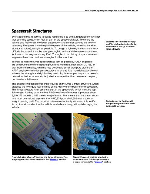
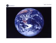
<strong>NASA</strong> Engineering Design Challenge: <strong>Spacecraft</strong> <strong>Structures</strong> 2007 – 9<strong>Spacecraft</strong> <strong>Structures</strong>Every pound that is carried to space requires fuel to do so, regardless of whetherthat pound is cargo, crew, fuel, or part of the spacecraft itself. The more thevehicle and fuel weigh, the fewer passengers and smaller payload the vehiclecan carry. Designers try to keep all the parts of the vehicle, including the skeleton(or structure), as light as possible. To design a lightweight structure is verydifficult, because it must be strong enough to withstand the tremendous thrust(or force) of the engines during liftoff. Throughout the history of space vehicles,engineers have used various strategies for the structure.In order to make the Ares spacecraft as light as possible, <strong>NASA</strong> engineersare constructing them of lightweight, strong materials, such as Al-Li 2195, analuminum-lithium alloy, which is less dense and stiffer than pure aluminum.<strong>NASA</strong> engineers also design structures that use as little material as possible toachieve the strength and rigidity they need. So, for example, they make use of anetwork of hollow tubular struts (called a truss) rather than use more compact,but heavier solid beams.This engineering design challenge focuses on the Ares V thrust structure, whichattaches the five liquid fuel engines of the Ares V to the body of the spacecraft.The thrust structure is an essential part of the spacecraft, which must be keptlightweight. As they burn, the five RS-68 engines of the Ares V produce about3,510,275 pounds (1,592 metric tons) of thrust. This means that the thrust structuremust bear a load equivalent to 3,510,275 pounds (1,592 metric tons) ofweight pushing on it. The thrust structure must not only withstand this terrificforce, it must transfer it to the vehicle in a balanced way, without damaging thevehicle.Students can calculate the “payload”to total weight ratios for (a)the family car and (b) a studentriding a bicycle.Students may be familiar withdesign strategies used to makelightweight bicycles.Figure 6.3. View of Ares V engines and thrust structure. Thisimage appears in a larger version in the "Masters" section.Figure 6.4. Ares V engines attached tothrust structure. This image appears ina larger version in the ”Masters” section.