Red Giant Grain Stir-Ator - David Manufacturing Co.
Red Giant Grain Stir-Ator - David Manufacturing Co.
Red Giant Grain Stir-Ator - David Manufacturing Co.
- No tags were found...

Create successful ePaper yourself
Turn your PDF publications into a flip-book with our unique Google optimized e-Paper software.
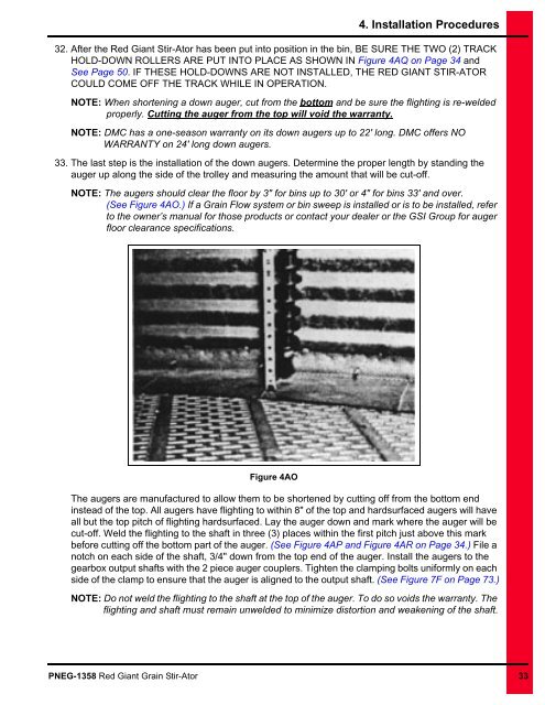
4. Installation Procedures32. After the <strong>Red</strong> <strong>Giant</strong> <strong>Stir</strong>-<strong>Ator</strong> has been put into position in the bin, BE SURE THE TWO (2) TRACKHOLD-DOWN ROLLERS ARE PUT INTO PLACE AS SHOWN IN Figure 4AQ on Page 34 andSee Page 50. IF THESE HOLD-DOWNS ARE NOT INSTALLED, THE RED GIANT STIR-ATORCOULD COME OFF THE TRACK WHILE IN OPERATION.NOTE: When shortening a down auger, cut from the bottom and be sure the flighting is re-weldedproperly. Cutting the auger from the top will void the warranty.NOTE: DMC has a one-season warranty on its down augers up to 22' long. DMC offers NOWARRANTY on 24' long down augers.33. The last step is the installation of the down augers. Determine the proper length by standing theauger up along the side of the trolley and measuring the amount that will be cut-off.NOTE: The augers should clear the floor by 3" for bins up to 30' or 4" for bins 33' and over.(See Figure 4AO.) If a <strong>Grain</strong> Flow system or bin sweep is installed or is to be installed, referto the owner’s manual for those products or contact your dealer or the GSI Group for augerfloor clearance specifications.Figure 4AOThe augers are manufactured to allow them to be shortened by cutting off from the bottom endinstead of the top. All augers have flighting to within 8" of the top and hardsurfaced augers will haveall but the top pitch of flighting hardsurfaced. Lay the auger down and mark where the auger will becut-off. Weld the flighting to the shaft in three (3) places within the first pitch just above this markbefore cutting off the bottom part of the auger. (See Figure 4AP and Figure 4AR on Page 34.) File anotch on each side of the shaft, 3/4" down from the top end of the auger. Install the augers to thegearbox output shafts with the 2 piece auger couplers. Tighten the clamping bolts uniformly on eachside of the clamp to ensure that the auger is aligned to the output shaft. (See Figure 7F on Page 73.)NOTE: Do not weld the flighting to the shaft at the top of the auger. To do so voids the warranty. Theflighting and shaft must remain unwelded to minimize distortion and weakening of the shaft.PNEG-1358 <strong>Red</strong> <strong>Giant</strong> <strong>Grain</strong> <strong>Stir</strong>-<strong>Ator</strong> 33