Red Giant Grain Stir-Ator - David Manufacturing Co.
Red Giant Grain Stir-Ator - David Manufacturing Co.
Red Giant Grain Stir-Ator - David Manufacturing Co.
- No tags were found...
Create successful ePaper yourself
Turn your PDF publications into a flip-book with our unique Google optimized e-Paper software.
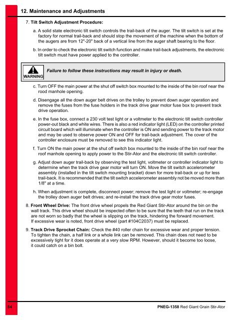
12. Maintenance and Adjustments7. Tilt Switch Adjustment Procedure:a. A solid state electronic tilt switch controls the trail-back of the auger. The tilt switch is set at thefactory for normal trail-back and should stop the movement of the machine when the bottom ofthe augers are from 12"-20" back of a vertical line from the auger shaft bearing to the floor.b. In order to check the electronic tilt switch function and make trail-back adjustments, the electronictilt switch must have power applied to the controller.Failure to follow these instructions may result in injury or death.c. Turn OFF the main power at the shut off switch box mounted to the inside of the bin roof near therood manhole opening.d. Disengage all the down auger belt drives on the trolley to prevent down auger operation andremove the fuses from the fuse holders in the track drive gear motor fuse box to prevent trackdrive operation.e. In the fuse box, connect a 230 volt test light or a voltmeter to the electronic tilt switch controllerpower-out black and white wires. There is also a red indicator light (LED) on the controller printedcircuit board which will illuminate when the controller is ON and sending power to the track motorand may be used to observe power ON and OFF for trail-back adjustment. The cover of thecontroller enclosure must be removed to see this indicator light.f. Turn ON the main power at the shut off switch box mounted to the inside of the bin roof near theroof manhole opening to apply power to the <strong>Stir</strong>-<strong>Ator</strong> and the electronic tilt switch controller.g. Adjust down auger trail-back by observing the test light, voltmeter or controller indicator light todetermine when the track drive gear motor will turn ON. Move the tilt switch accelerometerassembly (installed in the tilt switch mounting bracket) down for more trail-back or up for lesstrail-back. It is recommended that the tilt switch accelerometer assembly not be moved more than1/8" at a time.h. When adjustment is complete, disconnect power; remove the test light or voltmeter; re-engagethe trolley down auger belt drives; and re-install the track drive gear motor fuses.8. Front Wheel Drive: The front drive wheel propels the <strong>Red</strong> <strong>Giant</strong> <strong>Stir</strong>-<strong>Ator</strong> around the bin on thewall track. This drive wheel should be inspected often to be sure that the teeth that run on the trackare not worn so badly that the wheel is slipping on the track, hindering the forward movement.If excessive wear is noted, front drive wheel (part #104C2037) must be replaced.9. Track Drive Sprocket Chain: Check the #40 roller chain for excessive wear and proper tension.To tighten the chain, a half link or a whole link can be removed. This chain does not need to beexcessively tight for it does operate at a very slow RPM. However, should it become too loose,it could catch on a bin bolt.84 PNEG-1358 <strong>Red</strong> <strong>Giant</strong> <strong>Grain</strong> <strong>Stir</strong>-<strong>Ator</strong>


