Installation Manual - GTO/Pro
Installation Manual - GTO/Pro
Installation Manual - GTO/Pro

You also want an ePaper? Increase the reach of your titles
YUMPU automatically turns print PDFs into web optimized ePapers that Google loves.
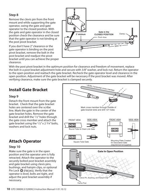
Step 8Remove the clevis pin from the frontmount and while supporting the gateoperator, swing the gate and gateoperator to the closed position. Withthe gate and gate operator in the closedposition check the clearance and be surethat the gate operator is not binding atthe post pivot bracket.If you don’t have 2” clearance or thegate operator is binding on the postpivot bracket, remove the bolt in thepost bracket and readjust the pivotbracket until you can achieve the properclearance.2" minimumGate in theCLOSED POSITIONPinch AreaMAX 16"With the post pivot bracket in the optimum position for clearance and freedom of movement, replacethe bolt in a post bracket adjustment hole and secure with 3/8” washer, and lock nut. Return the operatorto the open position and reattach the gate bracket. Recheck the gate operator level and clearance in theopen position. Adjustment of the gate bracket will be necessary if the post bracket was moved. Afterverifying clearance, make sure the gate bracket is clamped securely.ClampInstall Gate BracketStep 9Detach the front mount from the gatebracket. Check that the gate bracketholes are centered over the scribeline. Mark the gate in the center of thegate bracket holes. Remove the gatebracket and drill the 1/2” holes throughthe gate cross member and attach thegate bracket using the 1/2” x 2 3/4” bolts,washers and lock nuts.LEVEL horizontal cross memberMark cross member through middle ofgate bracket slots and drill 1/2" holesFRONT VIEW SIDE VIEW FRONT VIEW SIDE VIEWRound Tube & Chain Link GateAttach OperatorStep 10Make sure the gate is in the openposition and the operator arm is fullyretracted. Attach the operator to thesecurely bolted post bracket assemblyand gate bracket using clevis pins,bushings, and hairpin clips, or optionalPin Lock [FM345]. Verify that theoperator is level, bolts are tight, andadjust the post bracket assembly ifnecessary.Square Tube GateClevis Pin, Bushing, and Hairpin ClipFence PostMounting Plate Createdfor Decorative Gate(required but not supplied)Gate In Open PositionLevel Operator10 <strong>GTO</strong> 3000XLS/3200XLS Instruction <strong>Manual</strong> © 01.10.12