PowerLogic ION7550 / ION7650 User Guide - Schneider Electric
PowerLogic ION7550 / ION7650 User Guide - Schneider Electric
PowerLogic ION7550 / ION7650 User Guide - Schneider Electric

You also want an ePaper? Increase the reach of your titles
YUMPU automatically turns print PDFs into web optimized ePapers that Google loves.
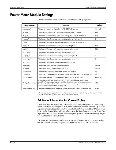
Chapter 4 - Basic Setup<strong>ION7550</strong> / <strong>ION7650</strong> <strong>User</strong> <strong>Guide</strong>Power Meter Module SettingsThe Power Meter module contains the following setup registers:Setup Register Function DefaultVolts Mode 1 The power system’s configuration – WYE, DELTA, Single, etc 4W-WYEPT Prim 1 The Potential Transformer’s primary winding rating for V1, V2 and V3 120PT Sec 1 The Potential Transformer’s secondary winding rating for V1, V2 and V3 120CT Prim 1 The Current Transformer’s primary winding rating for I1, I2 and I3 5CT Sec 1 The Current Transformer’s secondary winding rating for I1, I2 and I3 5V4 Prim 1 The Potential Transformer’s primary winding rating for V4 120V4 Sec 1 The Potential Transformer’s secondary winding rating for V4 120I4 CT Prim 1 The Current Transformer’s primary winding rating for I4 5I4 CT Sec 1 The Current Transformer’s secondary winding rating for I4 5I5 CT Prim 1 The Current Transformer’s primary winding rating for I5 5I5 CT Sec 1 The Current Transformer’s secondary winding rating for I5 5Vn Polarity The polarity of the Potential Transformer on Vn NormalIn Polarity The polarity of the Current Transformer on In NormalPhase Order The expected rotation of the voltage phases (ABC or ACB) ABCPhase Lbls The phase label format assigned to the outputs (ABC, RST, XYZ, RYB, RWB or 123) ABCkVA tot Method The method used to calculate kVA total (Vector Sum or Scalar Sum) Vector SumPF Sign ConventionDetermines which sign convention, IEEE or IEC, is used for the Power Metermodule’s PF sign output registers, and therefore how those values appear on thefront panel and in software. For more information on PF sign convention, see“Power Factor Interpretation” on page 60.IEEENominal Frequency The nominal frequency of the power system the meter is used in (50Hz or 60Hz) 60Hz1 These registers are typically set when the device is commissioned. Changing the values of theseregisters while the device is in service is not recommended.Additional Information for Current ProbesThe Current Probe phase calibration registers are setup registers in the Factorymodule that can be configured in a Telnet or HyperTerminal session. Up to threeseparate groups of registers (Factory Default, <strong>User</strong> Defined 1, and <strong>User</strong> Defined 2) canbe set up for three different Current Probes. In the Basic Setup menu, the Probe Typeregister is used to activate one of those register groups. Only the selected group isused in the meter’s calculations.For more information on configuring your meter’s non‐intrusive current probes,see the Current Probe Input Option document for the <strong>ION7550</strong> / <strong>ION7650</strong>.Page 58© 2007 <strong>Schneider</strong> <strong>Electric</strong>. All rights reserved.