cb-obs411 electrical mechanical data sheet - SE Spezial-Electronic ...
cb-obs411 electrical mechanical data sheet - SE Spezial-Electronic ...
cb-obs411 electrical mechanical data sheet - SE Spezial-Electronic ...
- No tags were found...

Create successful ePaper yourself
Turn your PDF publications into a flip-book with our unique Google optimized e-Paper software.
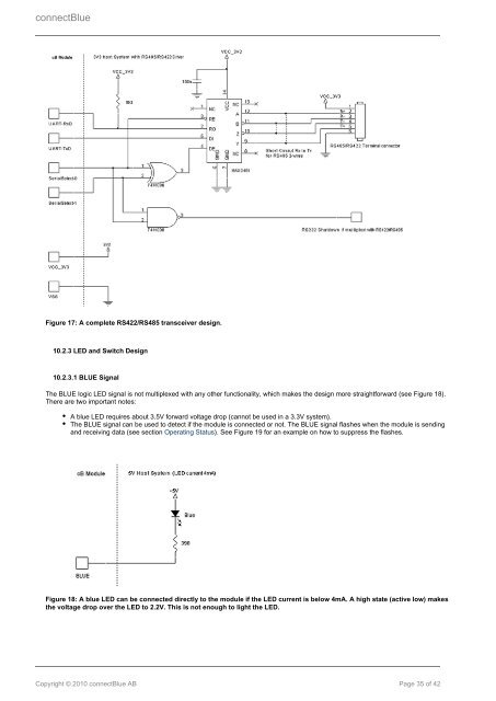
connectBlueFigure 17: A complete RS422/RS485 transceiver design.10.2.3 LED and Switch Design10.2.3.1 BLUE SignalThe BLUE logic LED signal is not multiplexed with any other functionality, which makes the design more straightforward (see Figure 18).There are two important notes:A blue LED requires about 3.5V forward voltage drop (cannot be used in a 3.3V system).The BLUE signal can be used to detect if the module is connected or not. The BLUE signal flashes when the module is sendingand receiving <strong>data</strong> (see section Operating Status). See Figure 19 for an example on how to suppress the flashes.Figure 18: A blue LED can be connected directly to the module if the LED current is below 4mA. A high state (active low) makesthe voltage drop over the LED to 2.2V. This is not enough to light the LED.Copyright © 2010 connectBlue AB Page 35 of 42