- Page 1 and 2: Irrigation Professionals with quest
- Page 3 and 4: Plot PlansIntroductionOne of the mo
- Page 5 and 6: Drawing ToolsThere are just a few t
- Page 7 and 8: Measure the PropertyTake careful me
- Page 9 and 10: Trees, water meters, and other item
- Page 11 and 12: Step 2 - Redraw On Graph PaperThe n
- Page 13 and 14: SymbolsIn order to distinguish betw
- Page 15 and 16: Make sure the drawing is dated and
- Page 17 and 18: Step 4 - Group Sprinklers Into Zone
- Page 19 and 20: Basic HydraulicsIntroductionHydraul
- Page 21 and 22: How Pressure is Created By the Weig
- Page 23 and 24: Does the Shape or Size of the Conta
- Page 25 and 26: L O W24 VAC 50-60 Hz60mA INRUSH60mA
- Page 27 and 28: Factors Affecting Dynamic PressureW
- Page 29 and 30: INSIDE DIAMETER (i.d.) of the pipe:
- Page 31 and 32: LENGTH is the fourth factor affecti
- Page 33 and 34: D) SDR -Standard Dimension Ratio -
- Page 35 and 36: 1. Look in the left column (FLOW G.
- Page 37 and 38: SummaryThere is a limited amount of
- Page 39 and 40: DefinitionsUse the diagram below al
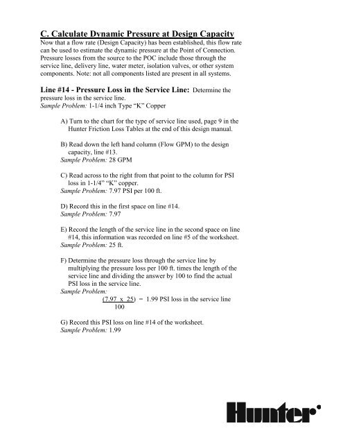
- Page 41 and 42: Calculating Dynamic Pressure at Des
- Page 43 and 44: D. Estimate Pressure Available at
- Page 45 and 46: Line #5 - Service Line: This is the
- Page 47: Line #11 - Volume Through the Meter
- Page 51 and 52: Line #16 - Pressure Loss in the Wat
- Page 53 and 54: Line #21 - Pressure Change Due to E
- Page 55 and 56: Design ProblemMany times, you will
- Page 57 and 58: III. Systems Supplied by a PumpCalc
- Page 59 and 60: D. Estimate Pressure Available at
- Page 61 and 62: Line #5 - Pressure at POC: If the P
- Page 63 and 64: Sample Problem: 13.5 GPMC) Read acr
- Page 65 and 66: D. Estimate Pressure Available at"W
- Page 67 and 68: (METERED SYSTEMS)Design Capacity an
- Page 69 and 70: (METERED SYSTEMS)Design Capacity an
- Page 71 and 72: (METERED SYSTEMS)Design Capacity an
- Page 73 and 74: (METERED SYSTEMS)Design Capacity an
- Page 75 and 76: (PUMP SYSTEMS)Design Capacity and W
- Page 77 and 78: (PUMP SYSTEMS)Design Capacity and W
- Page 79 and 80: Sprinkler SelectionIntroductionThe
- Page 81 and 82: Spray HeadsFixed spray heads may be
- Page 83 and 84: Selecting the Proper SprinklerNow t
- Page 85 and 86: Precipitation RateExpressed in inch
- Page 87 and 88: Sprinkler Watering PatternsMost spr
- Page 89 and 90: Choosing Nozzles for Gear Driven Ro
- Page 91 and 92: 5) Sprinkler Watering Patterns - Be
- Page 93 and 94: HydrozonesA hydrozone is a portion
- Page 95 and 96: Triangular spacing is usually the p
- Page 97 and 98: and flow rate, the smaller the spri
- Page 99 and 100:
perpendicular (see Figure 33). Many
- Page 101 and 102:
“symmetrical” layout, and they
- Page 103 and 104:
Head spacing in narrow areas is det
- Page 105 and 106:
Head placement is complicated becau
- Page 107 and 108:
Figure 40PGJ
- Page 109 and 110:
On larger slopes, a combination of
- Page 111 and 112:
SummarySprinkler head placement is
- Page 113 and 114:
Backflow PreventionIntroductionBack
- Page 115 and 116:
System LayoutLaying out a system be
- Page 117 and 118:
Backflow Preventer LocationLocal pl
- Page 119 and 120:
time. Station run time can be tempo
- Page 121 and 122:
Pipe Sizing Using the Friction Loss
- Page 123 and 124:
Backflow Preventer and Valve Sizing
- Page 125 and 126:
Friction LossesIntroductionCalculat
- Page 127 and 128:
5. Multiply your answer by the leng
- Page 129 and 130:
Friction Loss CalculationsZone Numb
- Page 131 and 132:
Sample Problem:1.67= 0.0167 psi los
- Page 133 and 134:
Step 2Step 3Step 4Step 5Step 6Sprin
- Page 135 and 136:
Using the acceptable 10% allowance:
- Page 137 and 138:
SummaryCalculating the friction los
- Page 139 and 140:
Friction Loss CalculationsZone Numb
- Page 141 and 142:
Friction Loss CalculationsZone Numb
- Page 143 and 144:
Precipitation RatesIntroductionToda
- Page 145 and 146:
Sprinkler Precipitation RatesVersus
- Page 147 and 148:
Area CoveredArc by Sprinkler Flow90
- Page 149 and 150:
The Sprinkler Spacing MethodThis me
- Page 151 and 152:
Use of Precipitation Rates in Lands
- Page 153 and 154:
Irrigation SchedulingIntroductionUl
- Page 155 and 156:
Crop coefficient. Different plants
- Page 157 and 158:
ET Evaporation of soil surface wate
- Page 159 and 160:
Soil Intake RateSoil texture will p
- Page 161:
What You Need to KnowAs previously